Note : Les descriptions sont présentées dans la langue officielle dans laquelle elles ont été soumises.
TITLE: SYSTEMS AND METHODS FOR A PLUG VALVE
INVENTORS: RYAN WEBER, JEFF ROBISON, BRAD ALLAN
CROSS-REFERENCE TO RELATED APPLICATION
[0001] This application claims the benefit of and priority to U.S.
Provisional Application
Serial No. 62/696,192, filed July 10, 2018, the contents of which are hereby
incorporated by
reference in their entirety.
BACKGROUND
[0002] In various industrial processes, such as in metal refining,
solids and liquids may be
conveyed from one vessel to another under high temperatures and high
pressures. Flow
control may be desired between two vessels so that the flow may be stopped
from time to
time.
SUMMARY
[0003] In various embodiments, a valve seat is provided comprising a
ceramic valve seat
insert positioned within a metal valve seat housing and comprising an
indentation
corresponding to a retention lip of the valve seat housing; and a compliant
sleeve positioned
coaxially around at least a portion of an outer surface of the valve seat
insert. The compliant
sleeve can comprise a pliable polymeric material, such as
polytetrafluoroethylene. The valve
seat housing can comprise a nickel chromium alloy, a titanium alloy, or a
zirconium alloy,
and further, a valve seat surface.
[0004] The valve seat surface can have a shape corresponding to a shape
of and capable of
receiving a portion of a plug head, such as a rounded end profile. The ceramic
valve seat
insert and the compliant sleeve can be press fit within the metal valve seat
housing.
[0005] In various embodiments, a valve assembly is provided comprising
a plug head
assembly comprising a plug head and a translating shaft; a valve seat
configured to receive
the plug head, wherein the plug head engages with a ceramic valve seat insert,
wherein the
1
CA 3049049 2019-07-10
ceramic valve seat insert is positioned within the valve seat and comprises an
indentation
corresponding to a retention lip of the valve seat, and wherein the valve seat
further
comprises a compliant sleeve positioned coaxially around at least a portion of
an outer
surface of the valve seat insert. The compliant sleeve can comprise a pliable
polymeric
material, such as polytetrafluoroethylene. The valve insert can comprise a
valve seat
surface, which can have a rounded end profile configured to receive a portion
of the plug
head. The valve seat can comprise a nickel chromium alloy, a titanium alloy,
or a zirconium
alloy, and the plug head can comprise a ceramic material.
[0006] In various embodiments, a method for assembling a valve seat
assembly is provided
comprising inserting a ceramic valve seat insert into a central bore of a
blank of compliant
material; reducing a diameter of the portion of the blank of compliant
material surrounding
the valve seat insert to form a compliant sleeve; inserting the valve seat
insert and the
compliant sleeve into a valve seat housing; and reducing a length of the blank
of compliant
material to form a compliant sleeve having an end profile. The valve seat
insert can
comprise an indentation at a distal end. The blank of compliant material can
comprise
polytetrafluoroethylene. The valve seat insert can comprise a valve seat
surface having a
rounded end profile configured to receive a portion of a plug head. The end
profile of the
compliant sleeve can be flush with a portion of the valve seat surface of the
valve seat insert.
BRIEF DESCRIPTION OF THE DRAWINGS
[0007] Various embodiments are particularly pointed out and distinctly
claimed in the
concluding portion of the specification. Below is a summary of the drawing
figures, wherein
like numerals denote like elements and wherein:
[0008] FIG. 1 illustrates an industrial process having a plug valve in
accordance with
various embodiments;
2
CA 3049049 2019-07-10
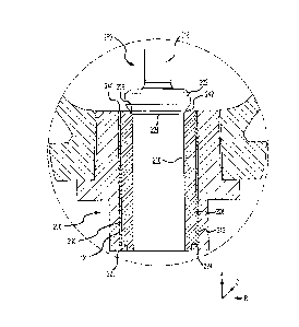
[0009]
FIG. 2 illustrates a cross section view of a plug valve seat configuration in
accordance with various embodiments;
[0010] FIG. 3A illustrates a cross section view of a partially-
assembled valve seat assembly
in accordance with various embodiments;
[0011] FIG. 3B illustrates another cross section view of a partially-
assembled valve seat
assembly in accordance with various embodiments; and
[0012]
FIG. 3C illustrates a cross section of an assembled valve seat assembly in
accordance
with various embodiments.
DETAILED DESCRIPTION
[0013] The detailed description of exemplary embodiments herein makes
reference to the
accompanying drawings, which show exemplary embodiments by way of illustration
and its
best mode. While these exemplary embodiments are described in sufficient
detail to enable
those skilled in the art to practice the inventions, it should be understood
that other
embodiments may be realized and that logical, chemical and mechanical changes
may be
made without departing from the spirit and scope of the inventions. Thus, the
detailed
description herein is presented for purposes of illustration only and not of
limitation. For
example, the steps recited in any of the method or process descriptions may be
executed in
any order and are not necessarily limited to the order presented. Moreover,
many of the
functions or steps may be outsourced to or performed by one or more third
parties.
Furthermore, any reference to singular includes plural embodiments, and any
reference to
more than one component or step may include a singular embodiment or step.
Also, any
reference to attached, fixed, connected or the like may include permanent,
removable,
temporary, partial, full and/or any other possible attachment option.
[0014] An isolation valve may operate to control the flow of a fluid or
slurry in a conduit.
For example, with reference to FIG. 1, ore processing system 100 is
illustrated. Ore
3
CA 3049049 2019-07-10
processing system 100 may be used in connection with high pressure acid
leaching
("HPAL"), pressure oxidation ("PDX") or any other mining or industrial
applications where
a solvent is mixed with material containing one or more metals and subjected,
for example,
to at least one of elevated temperatures or pressures.
[0015] A mixture of solids and liquids, which may be referred to as
slurry, may be subjected
to high temperatures and/or high pressures in autoclave 102. For example, ore
may be
mixed with strong acids (e.g. H2SO4) or strong bases (e.g., NaOH or NH3) and
may be
subjected to temperatures of from 80 C to 300 C or greater and total pressures
of from about
psi (-68 kPa) to 900 psi (-6,205 kPa). The slurry may have a pH of between 1
to 4 (in an
acidic application) or between about 10 to 14 (in a basic application). Such a
process may be
referred to as pressure leaching. An isolation valve, such as a plug valve
104, may be
positioned between autoclave 102 and a high pressure flash tank 106, and may
act to stop
flow between the two components of ore processing system 100. Low pressure
flash tank
108 is also illustrated for reference. Plug valve 104 may be paired with
isolation valve 111.
Isolation valve 111 may be a ball valve, plug valve, or any other suitable
valve. Although
described with reference to particular applications and operating conditions,
isolation valve
111 can be used in any suitable process.
[0016] Autoclave 102 may be sized according to industrial need, but is
in various
embodiments greater than 200 m3. The size of discharge line 110 may also vary,
but is in
various embodiments greater than 50 mm in diameter.
[0017] Plug valve 104 may comprise an angle-type isolation valve, and,
in various
embodiments, may be considered a full bore or nearly full bore valve. Plug
valve 104 may
be configured in a "flow under" orientation in that flow tends to force the
valve open, in
contrast to a "flow over" valve where flow tends to force the valve closed. In
that regard,
slurry is configured to flow from autoclave 102 to high pressure flash tank
106.
4
CA 3049049 2019-07-10
[0018] In other embodiments, plug valve 104 can comprise a non-isolation
valve, wherein
plug valve 104 is used to reduce or regulate pressure and/or flow (as opposed
an isolation
valve, which operates to stop flow through the valve). For example, plug valve
104 can
comprise a vent valve, a flash letdown valve, or a level control valve, among
other types of
non-isolation valves.
[0019] In operation, plug valve 104 may be actuated to a closed position
to fluidly isolate
autoclave 102 from high pressure flash tank 106. In response to actuation to
an open
position, plug valve 104 may experience slurry flow at high velocities,
temperatures and
pressures as slurry flows from autoclave 102 to high pressure flash tank 106.
[0020] With reference to FIG. 2, a plug head assembly portion of plug
valve 104 is shown in
cross section. Axial-Radial-Circumferential (A-R-C) axes are shown for
convenience in this
and other Figures. It should be noted that a first component shown displaced
in a positive
axial direction with respect to second component may be referred to as distal
to the second
component. Plug head assembly 250 comprises translating shaft 218 and plug
head 202.
Plug head 202 may comprise one or more materials. In various embodiments, plug
head 202
can comprise one or more metals, such as, for example, various steel alloys,
stainless steel,
titanium, ceramics such as silicon carbide (SiC), boron carbide (I34C),
tungsten carbide
(WC), and zirconia (ZrO2), and nickel chromium alloys, such as an austenitic
nickel-
chromium alloy such as the austenitic nickel-chromium alloy sold under the
trademark
INCONEL. Nickel chromium alloys may be well suited to high temperature
environments.
Conventional autoclave isolation valve trim may comprise metal with a thin
ceramic coating.
In operation, the thin ceramic coating may soon be abraded from the sliding
action of the
trim, damaged by crushing large solid pieces in the slurry flow and eroded by
the passing of
the high-velocity slurry. In such applications, monolithic ceramics may
provide much better
resistance to these abrasion, crushing and erosion potentials. Heretofore,
ceramic trim have
CA 3049049 2019-07-10
not been used in conventional autoclave ball valves due to great difficulty in
engineering and
constructing balls and seats that will not prematurely fail due to the brittle
nature of the
ceramic material. This tendency to failure of ball valve ceramic trim
naturally increases as
the trim size increases. In various embodiments, the angle plug configuration
and operation
make the engineering and construction of a durable ceramic trimmed valve
practical.
[0021] As noted herein, practical valve trim materials exclude ceramics.
Conventional
autoclave isolation ball valve operation tends to abrade the ball and seat
during opening and
closing, slurry flow erodes the ball and seat during opening and closing and
hard, solid
particles suspended in the slurry trap and crush as the ball closes on the
seat, thereby
damaging the sealing elements (or surfaces) of the seat and/or ball. A
repeated combination
of these actions soon initiates a leak path for high-pressure, highly erosive
flashing flow
which will quickly and dramatically increase the size of the leak path and
potentially destroy
the seat, ball and valve body. This results in an autoclave shutdown and the
associated large
production losses.
[0022] In various embodiments, plug head 202 may comprise a ceramic
material, as may
valve seat insert 216, as described herein. Ceramics are especially well
suited to high
erosion applications. Plug head 202 may have a varying geometry 204. For
example,
geometry 204 may be spherical, parabolic, flat, or any other suitable
geometric
configuration. As depicted in FIG. 2, geometry 204 is flat.
[0023] In a closed position, plug head 202 mates (e.g. contacts) with
valve seat assembly
200 about valve seat surface 206. When plug valve 104 is in the closed
position, valve seat
surface 206 circumferentially surrounds plug head 202. In that regard, contact
between plug
head 202 and valve seat surface 206 acts to resist and/or stop the flow of a
fluid or slurry
past plug head 202. Thus, in a closed position, plug valve 104 prevents the
flow of a fluid or
slurry past plug head 202.
6
CA 3049049 2019-07-10
[0024]
In various embodiments, valve seat assembly 200 comprises valve seat insert
216,
sleeve 210, and valve seat housing 212. Valve seat housing 212 may comprise
one or more
metals, for example, various steel alloys, stainless steel, titanium, and
nickel chromium
alloys, such as an austenitic nickel-chromium alloy such as the austenitic
nickel-chromium
alloy sold under the trademark INCONEL. Nickel chromium alloys may be well
suited to
high temperature environments.
[0025] In various embodiments, valve seat insert 216 comprises a
ceramic material. For
example, valve seat insert 216 can comprise a ceramic material, and valve seat
housing 212
can comprise a metallic material. In such embodiments, the ceramic material of
valve seat
insert 216 comprises a different coefficient of thermal expansion (CTE) than
the metallic
material of valve seat housing 212. As such, during operation of plug valve
104, the metallic
material of valve seat housing 212 can linearly expand at a different rate and
magnitude than
the ceramic material of valve seat insert 216. In general, metals have higher
coefficients of
thermal expansion than fine ceramics, creating a significant difference in the
overall
expansion of valve seat insert 216 (which linearly expands relatively less)
and valve seat
housing 212 (which linearly expands relatively more). For example, INCONEL
alloys can
range in coefficients of thermal expansion from approximately 13*10-6/ C to
approximately
16*Io-6/0C, and fine ceramics can range in coefficients of thermal expansion
from
approximately 2*10-6/0C to approximately 11*10-6/0C. As such, the greater
degree of linear
expansion in the metal material of valve seat housing 212 produces significant
axial tensile
loads on the ceramic material of valve seat insert 216, which can lead to
failure of the
ceramic material.
[0026] In various embodiments, a sleeve 210 surrounds at least a
portion of an outer surface
228 of the valve seat insert 216. For example, sleeve 210 can be positioned
coaxially
between outer surface 228 of valve seat insert 216 and an inner surface 238 of
valve seat
7
CA 3049049 2019-07-10
housing 212. Sleeve 210 may comprise a pliable material. In that regard,
sleeve 210 may
comprise various thermoplastics and/or thermosets and/or polymeric materials.
For
example, sleeve 210 can comprise rigid or semi-rigid polytetrafluoroethylene
(PTFE). In
various embodiments, being elastically deformable, sleeve 210 allows relative
movement
between valve seat insert 216 and valve seat housing 212 in response to fluid
or slurry
activity and/or in response to thermal expansion. Stated another way, sleeve
210 reduces
the transfer of axial tensile load caused by the difference in linear
expansion of valve seat
housing 212 and valve seat insert 216 by allowing the two components to slip
axially in
relation to each other. In particular, in response to an increase in
temperature, valve seat
housing 212 may expand in a radial direction to a greater degree than valve
seat insert 216,
as the CTE of valve seat housing 212 is greater than that of valve seat insert
216. The CTE
of sleeve 210, however, is greater than the CTE of valve seat housing 212 and
valve seat
insert 216, and thus sleeve 210 expands in a radial direction to assist in
retention of valve
seat insert 216 in valve seat housing 212. It is noted that ceramic materials,
such as those
that may be used in valve seat insert 216, may be relatively resistant to
compression loads. In
addition to expansion in the radial direction, in response to an increase in
temperature, valve
seat housing 212 may expand in an axial direction to a greater degree than
valve seat insert
216. In that regard, a tensile load is exerted by valve seat housing 212. If
valve seat insert
216 were directly contacted by valve seat housing 212, this tensile load may
be transferred to
valve seat insert 216, imparting a tensile load or a shear load on valve seat
insert 216, which
may be detrimental. However, since sleeve 210 is disposed between valve seat
insert 216
and valve seat housing 212, sleeve 210 mitigates the tensile load.
Moreover, in
embodiments where sleeve 210 comprises PTFE, given the low coefficient of
friction of
PTFE, valve seat housing 212 may beneficially slip with respect to sleeve 210.
In this
manner, valve seat housing 212 may be allowed to expand axially without
imparting a
8
CA 3049049 2019-07-10
tensile or shear load on valve seat insert 216, tending to decrease the
opportunity for valve
seat insert 216 to fail.
[0027] In various embodiments, sleeve 210 comprises a non-polymeric
material, such as a
silicon-based compound or a metallic material. For example, at elevated
temperatures (such
as, for example, above 260 C, a silicon-based compound or metallic material
may have a
higher CTE, which may improve performance of sleeve 210 (as compared to the
performance of a polymeric material at the same elevated temperature).
[0028] In various embodiments, valve seat housing 212 comprises a
retention lip 220 distal
to valve seat surface 206. For example, retention lip 220 can correspond to an
indentation
224 of valve seat insert 216, also positioned distal to valve seat surface
206. In such
embodiments, retention lip 220 engages with indentation 224 and prevents valve
seat insert
216 from dislodging from or disengaging with valve seat housing 212 during
flow through
plug valve 104.
[0029] The intended material flowing through an angle plug valve, and
the velocities at
which such material is intended to flow, is important in valve design. In
various
embodiments, a slurry comprising a solid phase and a liquid phase is intended
to flow
through angle plug valves. According to compressible flow theory and the
thermodynamics
of a multiphase system, the flow at the throat is choked and flowing at the
local speed of
sound, according to various embodiments. The flow before the throat behaves
like an
incompressible fluid and after the throat like a compressible, supersonic
fluid. As the area
expands downstream of the throat, the local properties of the fluid are a
function of the area
ratio of the throat to the local flow area and a function of the upstream
fluid supply
thermodynamic properties. The supersonic flow properties immediately
downstream of the
throat are independent of the flow conditions far downstream such as the
downstream tank
pressure. As the area expands, the velocity increases and the fluid density
decreases. These
9
CA 3049049 2019-07-10
,
properties are mathematically modeled according to the equations, references
and
description by Smith in US Patent No. 7,237,574, which is incorporated herein
by reference
in its entirety.
[0030] The seat face gap flow (Ag) area can be calculated as the seat
face ID times the face
gap (Ag = Dface X gface)= As the valve seat assembly 200 closes, the annular
flow area
between the plug head 202 and valve seat insert 216 decreases until the face
of the plug
cylindrical projection just begins to enter the bore diameter. This threshold
minimum flow
area coincides with a significantly larger seat face gap flow area (Ag). As
the flashing flow
expands after the throat, the velocity increases and the fluid density
decreases. In various
embodiments, the geometrical dimensions of the plug and seat pair are made
such that the
velocity and density of the flashing flow at Ag may reach velocities of 100
m/s or more with
a density 25% or less that of the fluid density upstream of the throat. The
correct
geometrical area ratio is determined using the aforementioned flow modeling
method. For
example, upstream source pressure of slurry may be between 5 bar and 60 bar,
temperature
may be between 100 degrees C and 300 degrees C, and slurry density may be
between 900
kg/m3 and 1,200 kg/m3. For example, in various embodiments, upstream source
pressure of
slurry may be between approximately 47 bar, temperature may be 253 degrees C,
and slurry
density may be 1,113 kg/m3. With the angle plug valve open in various
embodiments, flow
area ratio may be between 1/60 and 1/80, velocity may be between 80 m/s and
120 m/s, and
slurry density may be between 170 kg/m3 and 190 kg/m3. With the angle plug
valve open, in
various embodiments, flow area ratio may be approximately 1/73, velocity may
be 102 m/s,
and slurry density may be 181 kg/m3.
[0031] With reference to FIGs. 3A-3C, a method for assembling a valve
assembly in
accordance with various embodiments is illustrated. With reference to FIG. 3A,
valve seat
CA 3049049 2019-07-10
insert 216 is inserted into a compliant material blank 332. For example, valve
seat insert 216
is pressed into the central opening of compliant material blank 332.
[0032] Compliant material blank 332 can comprise a piece of compliant
material, such as
rigid or semi-rigid polytetrafluoroethylene, with a central bore having a
diameter sized to
correspond with the outer diameter of valve seat insert 216. In various
embodiments,
compliant material blank 332 comprises a square or round tube of compliant
material. In
other embodiments, compliant material blank 332 comprises a solid square,
rectangular, or
round shape into which a central bore is formed by, for example, boring or
machining.
[0033] With reference to FIG. 3B, compliant material blank 332 can be
reduced to a reduced
outer diameter 334. For example, reduced outer diameter 334 can correspond to
a desired
thickness of sleeve 210, such as, for example, between about 1.5 millimeters
and about 5
millimeters. In various embodiments, an outer dimension of compliant material
blank 332 is
reduced such that an extended end 336, protruding from an end 338 of valve
seat insert 216,
remains at a larger dimension than reduced outer diameter 334. For example,
compliant
material blank 332 can comprise a length greater than the length of valve seat
insert 216,
such extended end 336 can protrude from valve seat surface 206 of valve seat
insert 216.
[0034] With reference to FIG. 3C, after compliant material blank 332 is
reduced to a reduced
outer diameter 334 (forming sleeve 210), sleeve 210 and valve seat insert 216
can be inserted
into valve seat housing 212. For example, sleeve 210 and valve seat insert 216
can be sized
such that at room temperature, the two components fit within valve seat
housing 212 as a
press fit, a friction fit, or a threaded fit. Further, sleeve 210 can be
heated, inserted into
valve seat insert 216, and allowed to cool, resulting in a heat shrink type
fit. In various
embodiments, sleeve 210 and valve seat insert 216 are inserted into valve seat
housing 212
from the proximal end, such that retention lip 220 and indentation 224 are
aligned and in
contact with each other.
11
CA 3049049 2019-07-10
[0035] With reference back to FIG. 2, extended end 336 of compliant
material blank 332 can
be removed to form an end profile 240 of sleeve 210. For example, end profile
240 can be
flush with end 242 of valve seat insert 216, and/or valve seat housing 212,
forming a
relatively flat end profile.
[0036] Benefits and other advantages have been described herein with
regard to specific
embodiments. Furthermore, the connecting lines shown in the various figures
contained
herein are intended to represent exemplary functional relationships and/or
physical couplings
between the various elements. It should be noted that many alternative or
additional
functional relationships or physical connections may be present in a practical
system.
However, the benefits, advantages, and any elements that may cause any benefit
or
advantage to occur or become more pronounced are not to be construed as
critical, required,
or essential features or elements of the disclosure. The scope of the
disclosure is accordingly
to be limited by nothing other than the appended claims, in which reference to
an element in
the singular is not intended to mean "one and only one" unless explicitly so
stated, but rather
"one or more." Moreover, where a phrase similar to "at least one of A, B, or
C" is used in
the claims, it is intended that the phrase be interpreted to mean that A alone
may be present
in an embodiment, B alone may be present in an embodiment, C alone may be
present in an
embodiment, or that any combination of the elements A, B and C may be present
in a single
embodiment; for example, A and B, A and C, B and C, or A and B and C.
[0037] Systems, methods and apparatus are provided herein. In the
detailed description
herein, references to "various embodiments", "one embodiment", "an
embodiment", "an
example embodiment", etc., indicate that the embodiment described may include
a particular
feature, structure, or characteristic, but every embodiment may not
necessarily include the
particular feature, structure, or characteristic. Moreover, such phrases are
not necessarily
referring to the same embodiment. Further, when a particular feature,
structure, or
12
CA 3049049 2019-07-10
characteristic is described in connection with an embodiment, it is submitted
that it is within
the knowledge of one skilled in the art to affect such feature, structure, or
characteristic in
connection with other embodiments whether or not explicitly described. After
reading the
description, it will be apparent to one skilled in the relevant art(s) how to
implement the
disclosure in alternative embodiments.
[0038] Furthermore, no element, component, or method step in the
present disclosure is
intended to be dedicated to the public regardless of whether the element,
component, or
method step is explicitly recited in the claims. No claim element is intended
to invoke 35
U.S.C. 112(f) unless the element is expressly recited using the phrase "means
for." As used
herein, the terms "comprises", "comprising", or any other variation thereof,
are intended to
cover a non-exclusive inclusion, such that a process, method, article, or
apparatus that
comprises a list of elements does not include only those elements but may
include other
elements not expressly listed or inherent to such process, method, article, or
apparatus.
13
CA 3049049 2019-07-10