Note : Les descriptions sont présentées dans la langue officielle dans laquelle elles ont été soumises.
CA 03050249 2019-07-15
WO 2018/136290
PCT/US2018/013245
E-COMMERCE PACKAGE
REFERENCE TO RELATED APPLICATION
[0001] This application claims the benefit of priority under 35 U.S.C.
119(e) of United States provisional application serial number 62/449401 filed
on January
23, 2017, which is hereby incorporated by reference in its entirety.
BACKGROUND
[00021 The field of the invention relates generally to a package including a
carton with hingedly attached lid, and more particularly to a carton suitable
for use as an
e-commerce shipping container.
[0003] In recent years, the use of e-commerce shipping containers has rapidly
expanded as
customers increasingly purchase items over the Internet. A carton suitable for
rapid packing,
quick closure, and secure containment is desirable.
SUMMARY
[00041 According to a first aspect of the invention there is provided a lidded
container that
includes a tray and a hingedly attached lid. The tray includes a bottom wall,
front and rear
walls, two side walls, and a locking panel hingedly connected to an upper edge
of the front
wall, and the hingedly attached lid includes a top wall, first and second lid
side walls, a lid
front wall, and first and second corner gussets disposed on an interior
surface of the lid front
wall, the first and second corner gussets defining respective first and second
gusset angled
edges. The lidded container is configured to be placed in a closed and locked
configuration
by placing the lid over an open top of the tray and pressing downwards so as
to cause the
locking panel to fold outwardly until its exterior surface is at least
substantially adjacent to
the exterior surface of the front wall, such configuration allowing the first
gusset angled edge
to mate with a first complementary angled edge of the locking panel, and the
second gusset
angled edge to mate with a second complementary angled edge of the locking
panel so as to
lock the removable lid to the tray.
1
CA 03050249 2019-07-15
WO 2018/136290
PCT/US2018/013245
[0005] Optionally the locking panel is substantially trapezoidal.
[0006] Optionally the first and second corner gussets are substantially
triangular.
[0007] Optionally the tray portion includes first, second, third, and fourth
tray corner
gussets.
[0008) Optionally the lid front wall and lid side walls is positioned outward
of the tray front
wall and tray side walls.
0009] Optionally at least one perforation is provided in the top wall for
forming an
opening into the container.
[0010j Optionally, at least one perforation is provided which when broken
allows removal
of at least a portion of the lid front wall and disengage at least one second
gusset angled edge
from its complementary angled edge of the locking panel.
[001 I] Optionally the lid front wall defines an access notch in a lower edge
of the lid front
wall, the access notch configured to provide access to the locking panel when
the lidded
container is in the closed and locked configuration.
[0012] Optionally the locking panel defines a generally-rectangular notch in a
lower edge
of the locking panel.
[0013) Optionally the lid is configured to be unlocked from the tray by
pressing inwardly
on a portion of the locking panel that is exposed through the access notch to
move the first
and second gusset angled edges out of alignment with the first and second
complementary
angled edges, thereby allowing the lid to be unlocked from the tray.
[0014] In a second embodiment, a lidded container is disclosed which includes
a tray with a
hingedly attached lid. The tray includes a base wall, front and rear walls,
two side walls, and
a locking panel hingedly connected to an upper edge of the front wall. The
hingedly attached
lid includes a top wall, first and second lid side walls, a lid front wall,
and first and second
corner gussets disposed on an interior surface of the lid front wall, the
first and second corner
2
CA 03050249 2019-07-15
WO 2018/136290
PCT/US2018/013245
gussets defining respective first and second gusset angled edges. The lidded
container is
configured to be placed in a closed and locked configuration by placing the
lid over an open
top of the tray and pressing downwards so as to cause the locking panel to
fold inwardly until
its interior surface is at least substantially adjacent to the interior
surface of the front wall,
such configuration allowing the first gusset angled edge to mate with a first
complementary
angled edge of the locking panel, and the second gusset angled edge to mate
with a second
complementary angled edge of the locking panel so as to lock the removable lid
to the tray.
[0015] Optionally the locking panel is substantially trapezoidal.
[0016] Optionally the first and second corner gussets are substantially
triangular.
[0017] Optionally the tray includes first, second, third, and fourth tray
corner gussets.
[00181 Optionally the lid front wall and lid side walls are positioned inward
of the tray front
wall and tray side walls.
[0019] Optionally at least one perforation is provided in the top wall for
forming an
opening into the container.
[0020) Optionally at least one perforation is provided which when broken
allows removal
of at least a portion of the tray front wall and disengage at least one second
gusset angled
edge from its complementary angled edge of the locking panel.
[00211 In a third embodiment, a blank is disclosed for forming a lidded
container. The
blank includes a tray portion configured to form a tray and a lid portion
configured to form a
lid. The tray portion includes a first plurality of panels that are hingedly
connected to one
another and include, in series, a locking panel, the locking panel defining
first and second
angled locking edges, a front panel configured to form a front tray wall in a
set-up tray, a
bottom panel configured to form a bottom wall in the set-up tray, and a rear
panel configured
to form a rear wall in the set-up tray. The lid portion includes a top panel
configured to form
a top wall in a set-up lid, a lid front panel hingedly connected along a front
edge of the top
panel and configured to form front wall in the set-up lid, and a pair of
gusset panels
3
CA 03050249 2019-07-15
WO 2018/136290
PCT/US2018/013245
configured to form corner gussets within the front wall in the set-up lid, the
gusset panels
each defining a gusset angled edge. From the blank a set-up lidded container
is formed that is
configured to be placed in a closed and locked configuration by placing the
set-up lid over an
open top of the set-up tray and pressing downwards so as to cause the locking
panel to fold
outwardly until its exterior surface is at least substantially adjacent to the
respective exterior
surface of the front tray wall, such configuration allowing each gusset angled
edge to mate
with one of the first and second angled locking edge so as to lock the set-up
lid to the set-up
tray.
[0022] Within the scope of this application it is envisaged that the various
aspects,
embodiments, examples, features and alternatives set out in the preceding
paragraphs, in the
claims and/or in the following description and drawings may be taken
independently or in
any combination thereof For example, features described with one embodiment
are
applicable to all embodiments unless there is incompatibility of features.
BRIEF DESCRIPTION OF THE DRAWINGS
100231 Exemplary embodiments of the invention will now be described with
reference to
the accompanying drawings, in which:
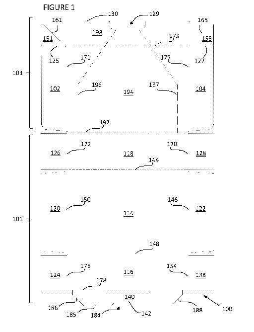
[00241 FIGURE 1 is a top plan view of a blank used to form one embodiment of a
carton.
[00251 FIGURE 2 is a perspective view of the blank shown in FIGURE 1.
[00261 FIGURE 3 is a perspective view of the assembled carton made from the
blank of
FIGURES 1 and 2, in an open configuration.
[00271 FIGURE 4 is a perspective view of the assembled carton of FIGURE 3, in
a closed
configuration.
[0028] FIGURE 5 is a perspective view of the assembled carton of FIGURE 4,
with a
partial cutaway showing details.
4
CA 03050249 2019-07-15
WO 2018/136290
PCT/US2018/013245
[00291 FIGURE 6 is a perspective view of a blank used to form another
embodiment of a
carton.
[0030] FIGURE 7 is a perspective view of a carton made from the blank of
FIGURE 6, in a
partially assembled configuration.
[00.311 FIGURE 8 is a perspective view of a carton of FIGURE 7, in a further
assembled
configuration.
[00371 FIGURE 9 is a perspective view of the carton of FIGURE 8, in an open
configuration.
[00331 FIGURE 10 is a perspective view of the carton of FIGURE 9, with a
locking flap
folded downward.
[0034] FIGURE 11 is a perspective view of the carton of FIGURE 10, showing the
lid
partially closed over the tray.
[0035] FIGURE 12 is a perspective view of the carton of FIGURE 11, showing the
lid fully
closed over the tray.
[0036] FIGURE 13 is a perspective view of the carton of FIGURE 12, with a
partial
cutaway showing details.
[0037) FIGURE 14 is a perspective view of the carton of FIGURE 13, with a
portion
having been torn open.
[00381 FIGURE 15 is a perspective view of another blank for forming a carton.
(.0039] FIGURE 16 is a perspective view of the assembled carton made from the
blank of
FIGURE 15, in a closed configuration.
[00401 FIGURE 17 is a perspective view of the carton of FIGURE 16, with a
partial
cutaway showing details.
CA 03050249 2019-07-15
WO 2018/136290
PCT/US2018/013245
[0041 FIGURE 18 is a top plan view of another blank used to form an embodiment
of a
carton.
100421 FIGURE 19 is a perspective view of the blank shown in FIGURE 18.
[0043) FIGURE 20 is a perspective view of the assembled carton made from the
blank of
FIGURES 18 and 19, in an open configuration.
[00441 FIGURE 21 is a perspective view of the assembled carton of FIGURE 20,
in a partly
closed configuration.
100451 FIGURE 22 is a perspective view of the assembled carton of FIGURE 20,
in a fully
configuration.
[00461 FIGURE 23 is a perspective view of the assembled carton of FIGURE 20,
with a
partial cutaway showing details.
DETAILED DESCRIPTION
[0047] Detailed descriptions of specific embodiments of cartons and blanks are
disclosed
herein. It will be understood that the disclosed embodiments are merely
examples of the way
in which certain aspects of the invention can be implemented and do not
represent an
exhaustive list of all ways the invention may be embodied. As used herein, the
word
"exemplary" is used expansively to refer to embodiments that serve as
illustrations,
specimens, models, or patterns. Indeed, it will be understood that the crates
and blanks
described herein may be embodied in various and alternative forms. The FIGURES
are not
necessarily to scale and some features may be exaggerated or minimized to show
details of
particular components. Well-known components, materials or methods are not
necessarily
described in detail, to avoid obscuring the present disclosure. Any specific
structural and
functional details disclosed herein are not to be interpreted as limiting, but
merely as a basis
for the claims and as a representative basis for teaching one skilled in the
art to variously
employ the invention.
6
CA 03050249 2019-07-15
WO 2018/136290
PCT/US2018/013245
[0048J In the embodiments detailed herein, the term "carton" refers, for the
non-limiting
purpose of illustrating the various features of the invention, to a container
for shipping,
transporting, storing, and/or dispensing articles, such as, e.g., one or more
products being
delivered to a consumer. However, it is contemplated that the teachings of the
invention can
be applied to various containers suitable for carrying a wide variety of
articles.
100491 Referring to FIG. 1, there is shown a blank 100 for forming a carton.
The blank 100
includes a tray portion 101 and lid portion 103. The blank 100 is formed from
a sheet of
suitable substrate. It is to be understood that, as used herein, the term
"suitable substrate"
includes all manner of foldable sheet material such as paperboard, corrugated
board,
cardboard, plastic, combinations thereof, and the like. It should be
recognized that one or
other numbers of blanks may be employed, for example, to provide the carton
described in
more detail below.
[0050j In one or more embodiments, blank 100 can be formed from a paperboard,
corrugated board, or cardboard in which one or both sides of the blanks, are
printed and/or
treated with one or more coatings, such as for example, one or more waterproof
coatings
and/or one or more coatings designed to provide a smooth and/or visually-
attractive surface
(e.g., a white or other colored surface). In one or more embodiments,
informational or
promotional material such as, e.g., a brand name or logo, can be printed on a
treated side.
[0051] Referring to FIG. 1, blank 100 is generally rectangular and is
generally symmetrical
about a central longitudinal axis. Tray blank 100 has a base panel 114. Base
panel 114 is
hingedly connected to: a front panel 116 via transverse fold line 148; a rear
panel 118 via
transverse fold line 144; a first side panel 120 via longitudinal fold line
150; and a second
side panel 122 via longitudinal fold line 146.
[0052] Foldably connected to the first side edge 176 of the front panel 116 is
a first front
gusset panel 124. Foldably connected to the second side edge 154 of the front
panel 116 is a
second front gusset panel 138. Foldably connected to a first side edge 172 of
rear panel 118
is a first rear gusset panel 126. Foldably connected to a second side edge 170
of rear panel
118 is a second rear gusset panel 128.
7
CA 03050249 2019-07-15
WO 2018/136290
PCT/US2018/013245
[00531 Foldably connected to the outer edge 178 of front panel 116 is a
locking panel 140.
Locking panel 140 is generally trapezoidal in shape and includes an inwardly-
angled first
side edge 186 and an inwardly-angled second side edge 188. A generally
rectangular notch
184 is struck from the locking panel outer edge 185. Notch 184 defines a notch
edge 142
[0054j Blank 100 includes a lid portion 103 extending from tray portion 101.
Top panel
194 is hingedly connected through transverse fold line 192 to rear panel 118.
Top panel 194
is also connected to a first lid side panel 102 via longitudinal fold line
171; and to second side
panel 104 via longitudinal fold line 175. Top panel 194 is also connected to
lid front panel
198 via transverse fold line 173.
[0055] Foldably connected to the first front edge 125 of the first lid side
panel 102 is a first
front gusset panel 151. Foldably connected to the second front edge 127 of the
second lid
side panel 104 is a second front gusset panel 155. Front gusset panels 151,
155 respectively
each have an angled edge 161, 165.
[0056j Lid front panel 198 includes a generally-rectangular access notch 129
struck from
the first side panel outer edge 130.
[0057j FIGURE 2 shows a perspective view of the blank 100 of FIGURE 1.
[00581 FIGURE 3 shows a perspective view of a carton 105 made from blank 100.
The
tray portion of carton 105 may be constructed by applying glue or other
adhesive to: an
outside surface of each of gusset panels 124, 126, 128 and 138 (or alternately
to at least
portions of an inside surface of side panels 120, 122). Gusset panels 124,
126, 128 and 138
may then be folded upward, and front and rear panels 116, 118 and side panels
120, 122
folded inwardly about their respective fold lines 148, 144, 150, 146 until
they are generally
perpendicular to base panel 114. This folding brings the outside surfaces of
the gusset panels
into contact with the inside surfaces, and the glue or other adhesive then
secures them
together. This results in the tray portion as seen to the front of FIGURE 3.
[00591 Instead of glue or other adhesive, other methods may be used to attach
together the
panels. For example, staples, tape, stitching, double-side tape, pressure-
sensitive adhesive,
8
CA 03050249 2019-07-15
WO 2018/136290
PCT/US2018/013245
and other suitable methods may be used to attach together the panels. This is
also true for the
other embodiments described herein.
100601 The hingedly attached lid portion of carton 105 may be constructed by
applying glue
or other adhesive to outside surfaces of gusset panel 151, 155 or to at least
portions of the
inside surface of lid front panel 198. The gusset panels 151, 155 may then be
folded
upwardly, and the first and second lid side wall panels 102, 104 folded
inwardly about their
respective fold lines 125, 127, 171, 175 until they are generally
perpendicular to top panel
194. This folding brings the outside surfaces of gusset panels 151, 155 into
contact with the
inside surface of lid front panel 198 and secures them together. This results
in lid portion as
shown to the back of FIGURE 3.
[00611 In some embodiments, carton 105 may include in its interior an adhesive
sheet that
may be of the type described in U.S. Patent No. 9,340,317, the entirety of
which is
incorporated herein by reference. A lower surface of the adhesive sheet may be
centered on
and adhered to interior surface of base panel 114 (as shown in FIGURE 3)
during assembly
of the carton 105. One or more articles 50 may be placed on the upper surface
of adhesive
sheet 106, and the adhesive sheet 106 may then be adhered to itself to envelop
the article 50
and fix it securely in place within the carton 105. This may be desired to
prevent damage to
the article 50 during transport.
[0062] The carton 105 may be closed with its lid side panels 102, 104
overlapping and on
the outside of tray side panels 120, 122. When closed, lid front panel 198 may
overlap and be
outside of tray front panel 116. To close the carton 105, as shown in FIGURE
4, the lid
portion is folded forward over the tray portion and pressed downwards. This
forces the
locking panel 140 to fold outwardly until its exterior surface (exterior' in
the sense as shown
in FIGURE 3) is substantially parallel and adjacent to (e.g., in face-
contacting relationship
with) the exterior surface of front panel 116. This configuration causes the
angled edges 161,
165 of lid gussets 151, 155 to automatically mate with respective
complementary angled
edges 186, 188 of locking panel 140, thereby locking the lid in place to
create a secure
connection between the lid and tray. Advantageously, the lid can be locked to
the tray
without the need for an adhesive connection therebetween, although in certain
embodiments
9
CA 03050249 2019-07-15
WO 2018/136290
PCT/US2018/013245
glue or other adhesive may be used to strengthen the connection. Instead of
glue or other
adhesive, other methods may be used to strengthen the connection. For example,
staples,
tape, stitching, double-side tape, pressure-sensitive adhesive, and other
suitable methods may
be used. This is also true for the other embodiments described herein.
[0063j To open the lid, a user can push inwardly on the portion of locking
panel 140 that is
exposed to view through access notches 129. This moves the angled edges 186,
188 of
locking panel 140 out of alignment with respective angled edges 161, 165 of
gussets 151, 155
allowing the lid to be lifted open from the tray.
[00641 As another way to open carton 105, a user can place his fingers or
thumbs at the
edges of access notch 129 and move his fingers or thumbs outward toward the
corners of the
carton, between angled edges 161, 165 of lid gussets 151, 155 and angled edges
186, 188 of
locking panel 140, then disengage the lid from the tray.
[00651 As another way to open carton 105, the lid and/or tray may be provided
with one or
more perforations or tear strips 196, 197 by which at least a portion of the
lid may be
removed or released from the tray. This method may be particularly useful if
the lid is glued
or otherwise secured to the tray.
[0066} As another way to open carton 105, the lid and/or tray may be provided
with one or
other perforations or tear strips by which at least a portion the lid may be
removed to release
the engagement between the tray and lid. This method, also, may be
particularly useful if the
lid is glued or otherwise secured to the tray. For example, at least portions
of transverse fold
line 173, first front edge 125, and/or second front edge 127 (see FIGURES 1
and 4) may be
perforated to allow at least a portion of lid front panel 198 to be removed to
disengage the lid
from the tray.
[0067j In some embodiments, one or both sides of blank 100 or carton 105 may
be treated
with a water-proof or water-resistant coating. Water resistance may be
considered
particularly desirable based on any likelihood that carton 105 will be
delivered to a location
that is exposed to the elements.
CA 03050249 2019-07-15
WO 2018/136290
PCT/US2018/013245
[0068J FIGURE 5 shows a perspective view of carton 105, with a cutaway portion
on the
front left corner to shows the angled edge 161 of lid gusset 151 locked into
place against
complementary angled edge 186 of locking panel 140. The lid gusset 151 and the
locking
panel 140 are substantially in a common plane that is tightly constrained
(e.g. as a middle
layer) between the more inward plane of tray front panel 116 and more outward
plane of lid
front panel 198. Thus, the lid is securely locked in place onto the tray.
[tR)691 In a variation of the carton 105, only one of the lid gussets may lock
into place with
an angled edge of locking panel 140. This may be sufficient to hold the lid
shut, at least
temporarily, for example until an adhesive connection has set between lid and
tray. In some
variations of the carton 105, the lid gussets 151, 155 may interlock with the
locking panel 140
while having lid gussets with a shape other than substantially triangular, or
a locking panel
with a shape other than substantially trapezoidal.
[0070j FIGURES 6 ¨ 14 show another embodiment of a blank 200 and a carton 205.
Certain features are similar to features already described, and are designated
with similar
numerals in the 200's. This embodiment differs in certain aspects from the
embodiment of
FIGURES 1-5. For example, as shown in FIGURE 6, tray gusset panels 224, 226,
228, and
238 may extend from side panels 220, 222 instead of extending from the tray
front and rear
panels. Also, the carton 205 may lack a notch in the outer edge of locking
panel 240.
[0071] FIGURE 7 shows a perspective view of a step in forming carton 205 from
blank
200. Glue or other adhesive may be applied to an outside surface of gusset
panels 224, 238
(or alternately to at least portions of an inside surface of tray front panel
216). Glue or other
adhesive may be applied to an outside surface of gusset panels 251, 255 (or
alternately to at
least portions of an inside surface of lid front panel 298). Gusset panels
224, 238, 251, 255
may then be folded upward. Tray front panel 216, lid front panel 298, and side
panels 202,
204, 220, 222 may be folded inwardly about their respective fold lines until
they are
generally perpendicular to base panel 214 and top panel 294. This folding
brings the outside
surfaces of the gusset panels into contact with the inside surfaces of tray
front panel 216 and
lid front panel 298, and the glue or other adhesive then secures them
together.
11
CA 03050249 2019-07-15
WO 2018/136290
PCT/US2018/013245
[00721 Glue or other adhesive may then be applied to the 'exterior' surfaces
of gusset
panels 226, 228 (or to at least portions of the inside surface of rear panel
218. The gusset
panels 226, 228 may then be folded inwardly about respective crease lines as
shown in
FIGURE 8. Next, as shown in FIGURE 9, rear panel 218 may be folded upwardly
along its
crease line with base panel 214. This brings the exterior surfaces of gusset
panels 226, 228
into contact with an interior surface of rear panel 218 for adhesive
attachment thereto. This
results in the fully-assembled tray carton 205 shown in FIGURE 9. A product
item (not
shown) may be loaded into carton 205.
[0073) Instead of glue or other adhesive, other methods may be used to attach
together the
panels. For example, staples, tape, stitching, double-side tape, pressure-
sensitive adhesive,
and other suitable methods may be used to attach together the panels.
[90741 Next, as seen in FIGURE 10, locking panel 240 may be folded outwardly
(arrow
M1) until its exterior surface (exterior' as seen in FIGURE 9) is
substantially parallel and
adjacent to (e.g., in face-contacting relationship with) the 'exterior'
surface of tray front panel
216. The natural flex or resilience of the paperboard may resist the folding,
and cause
locking panel 240 to remain flexed outward until the lid portion is closed
over the tray.
[00751 As shown in FIGURE 11, the lid may now be moved forward and over the
tray to
begin closing the carton 205. This configuration causes the angled edges 261,
265 of lid
gussets 251, 255 to automatically mate with respective complementary angled
edges 286, 288
of locking panel 240, thereby locking the lid in place to create a secure
closure of the carton
205 as shown in FIGURE 12. Advantageously, this secure closure can be achieved
without
the need for an adhesive connection therebetween, although in certain
embodiments glue or
other adhesive may be used to strengthen the connection. Instead of glue or
other adhesive,
other methods may be used to strengthen the connection. For example, staples,
tape,
stitching, double-side tape, pressure-sensitive adhesive, and other suitable
methods may be
used. This is also true for the other embodiments described herein.
12
CA 03050249 2019-07-15
WO 2018/136290
PCT/US2018/013245
[00761 As shown in FIGURE 12, carton 205 may be closed with its lid side
panels 202, 204
overlapping and on the outside of tray side panels 220, 222. When closed, lid
front panel 298
may overlap and be outside of tray front panel 216.
[0077) FIGURE 13 shows a perspective view of carton 205, with a cutaway
portion on the
front left corner to show the angled edge 261 of lid gusset 251 locked into
place against
complementary angled edge 286 of locking panel 240. The lid gusset 251 and the
locking
panel 240 are substantially in a common plane (middle layer) that is tightly
constrained
between the more inward plane of tray front panel 216 and the more outward
plane of lid
front panel 298. Thus, the lid is securely locked in place onto the tray.
[0078] To open the carton 205, a user can push inwardly on the portion of
locking panel
240 that that is exposed to view through access notch 229. This moves the
angled edges 286,
288 of locking panel 240 out of alignment with respective angled edges 161,
165 of gussets
151, 155 allowing the lid to be lifted up from the tray.
[0079j As another way to open carton 205, a user can place his fingers or
thumbs at the
edges of access notch 229 and move his fingers or thumbs outward toward the
corners of the
carton, between angled edges 161, 165 of the lid, and angled edges 286, 288 of
the locking
panel 240, to disengage the lid from the tray.
[0080] As seen in FIGURE 14, yet another way to open carton 205 is to provide
the lid
and/or tray with one or more perforations or tear strips 296, 297 by which the
lid or a portion
thereof may be released from the tray. This method may be particularly useful
if the lid is
glued or otherwise secured to the tray.
[00811 In a variation of the carton 205, only one of the lid gussets may lock
into place with
an angled edge of locking panel 240. This may be sufficient to hold the lid
shut, at least
temporarily, for example until an adhesive connection has set between lid and
tray. In some
variations of the carton 205, the lid gussets 251, 255 may interlock with the
locking panel 240
while having lid gussets with a shape other than substantially triangular, or
a locking panel
with a shape other than substantially trapezoidal.
13
CA 03050249 2019-07-15
WO 2018/136290
PCT/US2018/013245
[00821 As another way to open carton 205, the lid and/or tray may be provided
with one or
other perforations or tear strips by which at least a portion the lid may be
removed to release
the engagement between the tray and lid. This method, also, may be
particularly useful if the
lid is glued or otherwise secured to the tray. For example, at least portions
of transverse fold
line 273, first front edge 225, and/or second front edge 227 (see FIGURE 12)
may be
perforated to allow at least a portion of lid front panel 298 to be removed to
disengage the lid
from the tray.
[0083] Glue or other adhesive may be used to strengthen the connection between
the closed
lid and the tray. Instead of glue or other adhesive, other methods may be used
to strengthen
the connection. For example, staples, tape, stitching, double-side tape,
pressure-sensitive
adhesive, and other suitable methods may be used.
190841 In some embodiments, an adhesive sheet (as described earlier and shown
in
FIGURE 3) may be used within the carton to secure its contents.
[0085j In some embodiments, one or both sides of blank 200 or carton 205 may
be treated
with a water-proof or water-resistant coating. Water resistance may be
considered
particularly desirable based on the increased likelihood that carton 205 may
be delivered to a
location that is exposed to the elements.
[00861 FIGURES 15 ¨ 17 show another embodiment of a blank 300 and a carton
305.
Certain features are similar to the earlier embodiments, and are designated
with similar
numerals in the 300's. This embodiment differs in certain aspects from the
embodiment of
FIGURES 6-14. For example, as shown in FIGURE 15, blank 300 (and therefore
resulting
carton 305) may lack perforations for opening the carton..
[0087] FIGURE 16 shows a perspective view of the completed carton 305. FIGURE
17
shows a similar view, with a cutaway portion on the front left corner to show
the angled edge
361 of lid gusset 351 locked into place against complementary angled edge 386
of locking
panel 340. The lid gusset 351 and the locking panel 340 are substantially in a
common plane
(middle layer) that is tightly constrained between the more inward plane of
tray front panel
14
CA 03050249 2019-07-15
WO 2018/136290
PCT/US2018/013245
316 and more outward plane of lid front panel 398. Thus, the lid is securely
locked in place
onto the tray.
100881 As shown in FIGURE 16, carton 305 may be closed with its lid side
panels 302, 304
overlapping and on the outside of tray side panels 320, 322. When closed, lid
front panel 398
may overlap and be outside of tray front panel 316.
[0089j To open the carton 305, a user can push inwardly on the portion of
locking panel
340 that that is exposed to view through access notch 329. This moves the
angled edges 386,
388 of locking panel 340 out of alignment with respective angled edges 361,
365 of gussets
351, 355 allowing the lid to be lifted up from the tray.
[00901 As another way to open carton 305, a user can place his fingers or
thumbs at the
edges of access notch 329 and move his fingers or thumbs outward toward the
corners of the
carton, between angled edges 361, 365 of the lid, and angled edges 386, 388 of
the locking
panel 340, to disengage the lid from the tray.
100911 As another way to open carton 305, perforations may be provided in top
panel 394
and /or other panels (See FIGURES 1-14). As another way to open carton 305,
the lid and/or
tray may be provided with one or other perforations or tear strips by which at
least a portion
the lid may be removed to release the engagement between the tray and lid.
This method may
be particularly useful if the lid is glued or otherwise secured to the tray.
For example, at
least portions of transverse fold line 373, first front edge 325, and/or
second front edge 327
(see FIGURE 16) may be perforated to allow at least a portion of lid front
panel 398 to be
removed in order to disengage the lid from the tray.
[00921 In some embodiments, an adhesive sheet (as described earlier and shown
in
FIGURE 3) may be used within the carton to secure its contents. In a variation
of the carton
305, only one of the lid gussets may lock into place with an angled edge of
locking panel 340.
This may be sufficient to hold the lid shut, at least temporarily, for example
until an adhesive
connection has set between lid and tray. In some variations of the carton 305,
the lid gussets
351, 355 may interlock with the locking panel 340 while having lid gussets
with a shape
CA 03050249 2019-07-15
WO 2018/136290
PCT/US2018/013245
other than substantially triangular, or a locking panel with a shape other
than substantially
trapezoidal.
100931 Glue or other adhesive may be used to strengthen the connection between
the closed
lid and the tray. Instead of glue or other adhesive, other methods may be used
to strengthen
the connection. For example, staples, tape, stitching, double-side tape,
pressure-sensitive
adhesive, and other suitable methods may be used.
[0094j In some embodiments, one or both sides of blank 300 or carton 305 may
be treated
with a water-proof or water-resistant coating. Water resistance may be
considered
particularly desirable based on the increased likelihood that carton 305 may
be delivered to a
location that is exposed to the elements.
[0095) FIGURES 18-23 show another embodiment of a blank 400 and a carton 405.
Certain features are similar to features already described, and are designated
with similar
numerals in the 400's. In embodiment, as shown in FIGURE 18, tray gusset
panels 424, 426,
428, and 438 may extend from front panel 416 and rear panel 418. As will be
seen in the
following Figures, locking panel 440 may be turned inward in this embodiment.
[0096j Referring to FIG. 18, there is shown a blank 400 for forming a carton.
In many
aspects, blank 400 is similar to blank 100 previously described, although the
shapes of various
panels may differ slightly.
[0097] FIGURE 19 shows a perspective view of the blank 400 of FIGURE 18.
[0098] FIGURE 20 shows a perspective view of a carton 405 made from blank 400.
The
tray portion of carton 405 may be constructed by applying glue or other
adhesive to an inside
surface of each of gusset panels 424, 426, 428 and 438 (or alternately to at
least portions of
an outside surface of side panels 420, 422). Front and rear panels 416, 418
and side panels
420, 422 may then be folded upwardly and inwardly about their respective fold
lines 448,
444, 450, 446 until they are generally perpendicular to base panel 114. Gusset
panels 424,
426, 428 and 438 may then be folded inward, to bring the inside surfaces of
the gusset panels
into contact with the surfaces of the front, rear and side panels, so that the
glue or other
16
CA 03050249 2019-07-15
WO 2018/136290
PCT/US2018/013245
adhesive secures the panels together. This results in the tray portion as seen
to the front of
FIGURE 20.
100991 The hingedly attached lid portion of carton 405 may be constructed by
applying glue
or other adhesive to inside surfaces of gusset panels 451, 455 or to at least
portions of the
outside surface of lid front panel 498. The first and second lid side panels
402, 404 may then
be folded inwardly about their respective fold lines 471, 475 until they are
generally
perpendicular to top panel 494. Gusset panels 451, 455 may then be folded
inwardly about
their fold lines 425, 427 bringing their inner surfaces into contact with the
outside surface of
lid front panel 498, with the glue or other adhesive securing them together.
This results in lid
portion as shown to the back of FIGURE 20.
[00100} Instead of glue or other adhesive, other methods may be used to attach
together the
panels. For example, staples, tape, stitching, double-side tape, pressure-
sensitive adhesive,
and other suitable methods may be used to attach together the panels.
[001011 To close carton 405, the locking panel 440 is folded inward as shown
in FIGURE
21, and the lid portion is folded forward over the tray portion and pressed
downwards. This
forces the locking panel 440 to fold further inwardly until its interior
surface (interior' in the
sense as shown in FIGURE 20) is substantially parallel and adjacent to (e.g.,
in face-
contacting relationship with) the interior surface of front panel 416. As the
lid portion is
further closed, this configuration causes the angled edges 461, 465 of lid
gussets 451, 455 to
automatically mate with respective complementary angled edges 486, 488 of
locking panel
440, thereby locking the lid in place to create a secure connection between
the lid and tray.
Advantageously, the lid can be locked to the tray without the need for an
adhesive connection
therebetween, although in certain embodiments glue or other adhesive may be
used to
strengthen the connection. Instead of glue or other adhesive, other methods
may be used to
strengthen the connection. For example, staples, tape, stitching, double-side
tape, pressure-
sensitive adhesive, and other suitable methods may be used.
[00102) As shown in FIGURES 21 and 22, carton 405 may be closed with its lid
side
panels 402, 404 inside of tray side panels 420, 422. When closed, lid front
panel 498 may be
17
CA 03050249 2019-07-15
WO 2018/136290
PCT/US2018/013245
inside of tray front panel 416. To better fit within the tray, for example to
more readily clear
the tray front panel when the lid is being closed, lid front panel 498 may be
slanted slightly
inward. One way to achieve this is to form front edges 425, 427 of the lid
side panels
402,404 (these edges also being the hinge/fold lines attaching the gusset
panel 451, 455) at an
appropriate angle. Also, the angled edges 461, 465 may be adjusted accordingly
to closely
meet with the respective angled edges 486, 488 of locking panel 440. As best
shown in
FIGURE 18, fold line 473 between top panel 494 and lid front panel 498 (and
fold lines 471,
475 between the top panel and the lid side panels 402, 404) may be moved
slightly inward to
allow the lid to fit better within the tray.
1001031 To open the lid, a user can push his fingers between locking panel 440
that and lid
front panel 498 to force angled edges 486, 488 of locking panel 440 out of
alignment with
respective angled edges 461, 465 of gussets 451, 455 allowing the lid to be
lifted open from
the tray.
100104] As another way to open carton 405, the lid and/or tray may be provided
with one or
more perforations or tear strips (see FIGURES 1-14) by which the lid may be
released from
the tray, or a portion of the lid and/or tray removed. This method may be
particularly useful if
the lid is glued or otherwise secured to the tray.
[00105] As yet another way to open carton 305, the lid and/or tray may be
provided with
one or more perforations or tear strips by which at least a portion the lid
may be removed to
release the engagement between the tray and lid. This method, also, may be
particularly
useful if the lid is glued or otherwise secured to the tray. For example, at
least portions of
transverse fold line 448, first side edge 476 of the front panel, and/or
second side edge 454 of
the front panel (see FIGURES 18 and 22) may be perforated to allow at least a
portion of tray
front panel 416 to be removed in order to disengage the lid from the tray.
[OM 06/ In some embodiments, carton 405 may include in its interior an
adhesive sheet (as
shown in FIGURE 3) during assembly of the carton, for more securely holding
articles placed
within the carton. In some variations of the carton 405, only one of the lid
gussets may lock
into place with an angled edge of locking panel 440. This may be sufficient to
hold the lid
18
CA 03050249 2019-07-15
WO 2018/136290
PCT/US2018/013245
shut, at least temporarily, for example until an adhesive connection has set
between lid and
tray. In some variations of the carton 405, the lid gussets 451, 455 may
interlock with the
locking panel 440 while have lid gussets with a shape other than substantially
triangular, or a
locking panel with a shape other than substantially trapezoidal.
[001071 In some embodiments, one or both sides of blank 400 or carton 405 are
treated
with a water-proof or water-resistant coating. Water resistance may be
considered
particularly desirable based on any likelihood that carton 405 will be
delivered to a location
that is exposed to the elements.
[0010$] FIGURE 22 shows a perspective view of carton 405 in a closed
configuration.
FIGURE 23 shows a front view with a cutaway portion on the front left corner
to show the
angled edge 461 of lid gusset 451 locked into place against complementary
angled edge 486
of locking panel 440. The lid gussets 451, 455 and the locking panel 440 are
substantially in a
common plane that is tightly constrained between the plane of tray front panel
416 and lid
front panel 498. Thus, the lid is securely locked in place onto the tray.
Here, viewed from
the front, the front wall of the carton includes as an outward layer the tray
front panel 416, as
a middle layer the locking panel 440 and lid gussets 451, 455, and as an
inward layer the lid
front panel 498.
[00109] Exemplary embodiments of blanks and methods for forming containers are
described above in detail. The apparatus and methods are not limited to the
specific
embodiments described herein, but rather, components of apparatus and/or steps
of the
methods may be utilized independently and separately from other components
and/or steps
described herein. For example, the methods may also be used in combination
with other
containers and methods, and are not limited to practice with only the
containers and methods
as described herein. Rather, the exemplary embodiment can be implemented and
utilized
with many other container applications.
[OM 10) Although specific features of various embodiments of the invention may
be shown
in some drawings and not in others, this is for convenience only. In
accordance with the
19
CA 03050249 2019-07-15
WO 2018/136290
PCT/US2018/013245
principles of the invention, any feature of a drawing may be referenced and/or
claimed in
combination with any feature of any other drawing.
[00111] This written description uses examples to disclose the invention,
including the best
mode, and to enable any person skilled in the art to practice the invention,
including making
and using any devices or systems and performing any incorporated methods. The
patentable
scope of the invention is defined by the claims, and may include other
examples that occur to
those skilled in the art. Such other examples are intended to be within the
scope of the claims
if they have structural elements that do not differ from the literal language
of the claims, or if
they include equivalent structural elements with insubstantial differences
from the literal
language of the claims.