Note : Les descriptions sont présentées dans la langue officielle dans laquelle elles ont été soumises.
CA 03050371 2019-07-16
WO 2018/150413
PCT/IL2018/050076
TOOL BODY HAVING AN INNER INSERT RECEIVING POCKET WITH RESILIENT
CLAMPING MEMBER, CUTTING TOOL AND CHAMFERING CUTTING INSERT
THEREFOR
FIELD OF THE INVENTION
The subject matter of the present application relates to cutting tools having
a tool body
with an outer insert receiving pocket and an inner insert receiving pocket,
for releasably retaining
a chamfering cutting insert therein, in general, and to such tool bodies with
a resilient clamping
member for resiliently clamping the chamfering cutting insert, in particular.
BACKGROUND OF THE INVENTION
Cutting tools can have a tool body that can be provided with an outer insert
receiving
pocket for retaining a grooving/parting insert therein and an inner insert
receiving pocket for
releasahly retaining a chamfering cutting insert therein by a clamping member.
Examples of
such cutting tools are disclosed in, for example, US 9,162,296 and WO
1999/028073, where the
clamping member is a retaining screw.
Other cutting tools can be provided with a cutting insert that performs a dual
cutting role.
Such a cutting insert is provided with a parting section to part the workpiece
and a chamfering
section to chamfer the workpiece after the parting process is compete. An
example of such
cutting insert is disclosed in, for example, WO 2008/140191.
It is an object of the subject matter of the present application to provide a
new and
improved tool body.
It is an object of the subject matter of the present application to provide a
tool body
having an interiorly disposed inner insert receiving pocket, for releasably
retaining a chamfering
cuttim:2; insert therein by a resilient clamping member.
It is an object of the subject matter of the present application to provide a
new and
improved chamfering cutting insert.
It is an object of the subject matter of the present application to provide a
new and
improved cutting tool.
-1-
CA 03050371 2019-07-16
WO 2018/150413
PCT/IL2018/050076
SUMMARY OF THE INVENTION
In accordance with a first aspect of the subject matter of the present
application there is
provided a tool body comprising:
two opposing body side surfaces and a body peripheral surface extending
therebetween;
a peripherally disposed outer insert receiving pocket; and
an interiorly disposed inner insert receiving pocket comprising a resilient
clamping
member configured to resiliently retain a chamfering cutting insert therein
without the use of an
additional, separate clamping device.
In accordance with a second aspect of the subject matter of the present
application there
is provided a non-indexable chamfering cutting insert, having an insert
longitudinal axis
defining a forward to rearward direction, the cutting insert comprising:
opposing insert front and rear end surfaces and an insert peripheral surface
extending
therebetween, the insert peripheral surface comprising an insert top surface;
a non-cutting edge formed by the intersection of the insert front end surface
and the insert
top surface; and
at least one laterally protruding chamfering portion comprising a chamfering
cutting
edge; wherein:
in a top view of the insert, the non-cutting edge extends on both sides of a
vertical plane
containing the insert longitudinal axis and passing through the insert top
surface; and
the insert top surface comprises an insert top raised portion comprising an
insert top
abutment surface and an insert top lowered portion comprising an insert top
non-abutment
surface, the insert top lowered portion extending from the insert rear end
surface towards the
insert top raised portion.
In accordance with a third aspect of the subject matter of the present
application there is
provided a cutting tool comprising:
a tool body of the sort described above; and
a cutting insert, of the sort described above, resiliently clamped in the
inner insert
receiving pocket by the resilient clamping member.
- 2 -
CA 03050371 2019-07-16
WO 2018/150413
PCT/IL2018/050076
In accordance with a fourth aspect of the subject matter of the present
application there is
provided a non-indexable chamfering cutting insert, having an insert
longitudinal axis defining a
forward to rearward direction, the cutting insert comprising:
opposing insert front and rear end surfaces and an insert peripheral surface
extending
therebetween, the insert peripheral surface comprising an insert top surface;
a vertical plane containing the insert longitudinal axis and passing through
the insert top
surface;
a non-cutting edge formed by the intersection of the insert front end surface
and the insert
top surface; and
at least one laterally protruding chamfering portions comprising a chamfering
cutting
edge; wherein:
each chamfering portion is located at a forward end of the cutting insert;
in a top view of the insert, the non-cutting edge extends on both sides of the
vertical plane
containing the insert longitudinal axis; and
in said top view of the insert, the insert's total length taken along the
insert longitudinal
axis is larger than the insert's total width taken perpendicular to the
vertical plane.
It is understood that the above-said is a summary, and that features described
hereinafter
may be applicable in any combination to the subject matter of the present
application, for
example, any of the following features may be applicable to the tool body
and/or cutting insert
and/or cutting tool:
The resilient clamping member can be disposed between the inner insert
receiving pocket
and a resilience SUL
The resilient clamping member can be a candlever having a clamping member
fixed end
and a clamping member free end.
The inner insert receiving pocket can extend along a pocket longitudinal axis
which
passes through a pocket opening end and a pocket distal end, the pocket
opening end being
located closer to the body peripheral surface than the pocket distal end. The
inner insert
receiving pocket can transitions into an insert insertion clearance region at
the pocket opening
end. The insert insertion clearance region can have a larger dimension, as
measured in a
direction perpendicular to the pocket longitudinal axis, than the inner insert
receiving pocket.
- 3 -
CA 03050371 2019-07-16
WO 2018/150413
PCT/IL2018/050076
The tool body can comprise a through recess opening out to the two body side
surfaces,
and at least partially circumferentially bounded by a recess circumferential
surface. The
resilient clamping member can extend into the through recess. The interiorly
disposed inner
insert receiving pocket can be formed by the resilient clamping member and a
recess pocket
portion of the recess circumferential surface.
The resilient clamping member can be connected to the recess circumferential
surface.
The through recess can be spaced apart from the body peripheral surface.
The through recess can open out to the body peripheral surface.
The tool body can have a body central axis that intersects the two body side
surfaces.
The two body side surfaces can be planar and perpendicular to the body central
axis.
The tool body can be disc-like and have a body central axis that intersects
the two body
side surfaces. The tool body can be rotatable about the body central axis in a
rotational
direction. The inner insert receiving pocket is closer to the body central
axis than is the outer
insert receiving pocket.
The tool body can be a cutting blade and have a body central axis that
intersects the two
body side surfaces. The tool body can be mirror symmetric about a transverse
plane containing
the body central axis. The inner insert receiving pocket is closer to the both
the transverse
plane and body central axis, than is the outer insert receiving pocket.
The cutting insert can comprise exactly two chamfering portions that oppose
each other,
each chamfering portion having a chamfering cutting edge.
The two chamfering cutting edges can be spaced apart by the non-cutting edge
formed by
the intersection of the insert front end surface and the insert top surface
and extend rearwardly
of the non-cutting edge.
The insert top raised portion can extend from the insert front end surface.
The insert top raised portion and the insert top lowered portion can be
connected by an
insert top intermediate surface that can be oriented transversely to the
insert raised and insert
top lowered portions.
The insert top abutment surface can extend to the insert top intermediate
surface.
The insert top abutment surface can be generally V-shaped in an axially
perpendicular
cross-section.
Each chamfering portions can be located at a forward end of the cutting
insert.
- 4 -
CA 03050371 2019-07-16
WO 2018/150413 PCT/IL2018/050076
The insert top non-abutment surface can be planar.
The insert top raised portion has an insert top raised portion length. The
insert top
lowered portion has an insert top lowered portion length. The insert top
raised portion length is
less than the insert top lowered portion length.
In a top view of the insert, the insert's total length taken along the insert
longitudinal
axis can be larger than the insert's total width taken perpendicular to the
vertical plane.
The resilient clamping member can comprise a clamping abutment surface. The
recess
pocket portion can comprise a pocket abutment surface located opposite the
clamping abutment
surface. The insert peripheral surface can comprise an insert bottom surface
opposite the insert
top surface. The insert bottom surface can comprise an insert bottom abutment
surface. The
insert bottom abutment surface can abut the pocket abutment surface. The
clamping abutment
surface resiliently engages the insert top abutment surface.
The insert top non-abutment surface can be spaced apart from the resilient
clamping
member.
BRIEF DESCRIPTION OF THE FIGURES
For a better understanding of the present application and to show how the same
may be
carried out in practice, reference will now be made to the accompanying
drawings, in which:
Fig. 1 is a perspective view of a cutting tool in accordance with the present
application;
Fig. 2 is an exploded perspective view showing a through recess of the cutting
tool
shown in Fig. 1 in accordance with an embodiment of the present application;
Fig. 3 is a side view of the through recess in Fig. 2;
Fig. 4 is a side view of the through recess in accordance with another
embodiment of the
present application;
Fig. 5 is a side view of an inner cutting insert in Fig. 1;
Fig. 6 is a top view of the cutting insert in Fig. 5;
Fig. 7 is an analogous view shown in Fig. 3, when the insert receiving pocket
is in an
open position; and
Fig. 8 is a side view of another cutting tool in accordance with the present
application.
- 5 -
CA 03050371 2019-07-16
WO 2018/150413
PCT/IL2018/050076
It will be appreciated that for simplicity and clarity of illustration,
elements shown in the
figures have not necessarily been drawn to scale. For example, the dimensions
of some of the
elements may be exaggerated relative to other elements for clarity, or several
physical
components may be included in one functional block or element. Further, where
considered
appropriate, reference numerals may be repeated among the figures to indicate
corresponding or
analogous elements.
DETAILED DESCRIPTION OF THE INVENTION
In the following description, various aspects of the subject matter of the
present
application will be described. For purposes of explanation, specific
configurations and details
are set forth in sufficient detail to provide a thorough understanding of the
subject matter of the
present application. However, it will also be apparent to one skilled in the
art that the subject
matter of the present application can be practiced without the specific
configurations and details
presented herein.
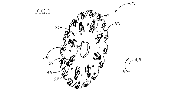
Attention is first drawn to Fig. I, showing a cutting tool 20, depicting an
aspect of the
present application, having a tool central axis A. In this non-limiting
example shown in Fig. I,
the cutting tool 20 is a milling cutting tool. In particular, the milling
cutting tool is a rotary
slotting cutter, suitable for slotting cutting operations, and being rotatable
about the tool central
axis A in a rotational direction R. The cutting tool 20 may exhibit rotational
symmetry about the
tool central axis A. The cutting tool 20 has a cutting insert 22 which can be
typically made from
cemented carbide. The cutting tool 20 has a tool body 24 which can be
typically made from
steel.
It is noted that the term "slotting cutter" as used herein may be replaced
with other terms
.. applicable in the metal cutting field for such cutting tools, for example,
"slot milling cutter",
"slitting cutter", "grooving cutter", "slot mill cutter", "groove milling
cutter", "side milling
cutter", "disc milling cutter", and the like.
Reference is now made particularly to Fig. I. The tool body 24 has a body
central axis B
that is co-incident with the tool central axis A. The tool body 24 includes
two opposing body
side surfaces 26 and a body peripheral surface 28 that extends therebetween.
The body central
axis B intersects the two body side surfaces 26. The body central axis B
extends through a
central portion of the body side surfaces 26. In accordance with some
embodiments of the
- 6 -
CA 03050371 2019-07-16
WO 2018/150413
PCT/IL2018/050076
subject matter of the present application, the two opposing body side surfaces
26 can be planar
and perpendicular to the body central axis B. The tool body 24 can be disc-
like and the body
central axis B forms an axis of rotation about which the tool body 24 is
rotatable in a rotational
direction R.
The tool body 24 includes an outer insert receiving pocket 58 that adjoins the
body
peripheral surface 28. That is to say the outer insert receiving pocket 58 is
peripherally disposed
and is suitable for, e.g., a grooving cutting insert, since its cutting edge
would be accessible to
the work-piece.
Referring now to Figs. 2 and 3, the tool body 24 includes a through recess 30.
The
through recess 30 is at least partially circumferentially bounded by a recess
circumferential
surface 32. The recess circumferential surface 32 extends between, and opens
out to, the two
body side surfaces 26. In accordance with some embodiments of the subject
matter of the
present application, the through recess 30 can also open out also to the body
peripheral surface
28. In such a configuration, the recess circumferential surface 32 intersects
the body peripheral
surface 28 and only partially bounds the through recess 30. Stated
differently, the through
recess 30 is "open". However, in accordance with some other embodiments of the
subject
matter of the present application, the through recess 30 can be spaced apart
from the body
peripheral surface 28. In such a configuration, the recess circumferential
surface 32 does not
intersect the body peripheral surface 28 and fully bounds the through recess
30. Stated
differently, the through recess 30 is "closed". Advantageously, the periphery
of the cutting tool
20 is more rigid when the through recess 30 is closed.
As best seen in Figs. 3 and 4, the recess circumferential surface 32 includes
a recess
pocket portion 34. The tool body 24 further includes a resilient clamping
member 36, which is
able to be undergo elastic displacement relative to the recess pocket portion
34. The resilient
clamping member 36 extends into the through recess 30. In accordance with some
embodiments
of the subject matter of the present application, the resilient clamping
member 36 can be a
cantilever having a clamping member fixed end 38 and a clamping member free
end 40. Thus,
the resilient clamping member 36 can be said to protrude into the through
recess 30. The
resilient clamping member 36 can be connected to the recess circumferential
surface 32. The
resilient clamping member 36 can be integrally formed with the tool body 24 to
have one-piece
unitary construction therewith. The resilient clamping member 36 can be
bounded on one side
- 7 -
CA 03050371 2019-07-16
WO 2018/150413
PCT/IL2018/050076
by a resilience slit 42 to allow for elastic displacement. The resilient
clamping member 36
includes a clamping abutment surface 44, for resiliently engaging a
corresponding surface on the
cutting insert 22.
The tool body 24 includes an inner insert receiving pocket 46, for releasahly
retaining a
chamfering cutting insert 22 therein. Generally speaking, the inner insert
receiving pocket 46 is
closer to the body central axis B than is the outer insert receiving pocket
58. That is to say, the
inner insert receiving pocket 46 is interiorly disposed and not suitable for,
e.g., a grooving
cutting insert, since its cutting edge would not be accessible to the work-
piece. Such an inner
insert receiving pocket 46, however, is suitable for a chamfering cutting
insert (as described
below), for chamfering a pre-cut groove.
The inner insert receiving pocket 46 is formed by the resilient clamping
member 36 and
the recess pocket portion 34. The inner insert receiving pocket 46 extends
along a pocket
longitudinal axis P. The inner insert receiving pocket 46 includes a pocket
opening end 48 and
an opposing pocket distal end 50, the pocket opening end 48 being located
closer to the body
peripheral surface 28 than the pocket distal end 50. The pocket longitudinal
axis P passes
through the pocket opening end 48 and the pocket distal end 50.
In accordance with some embodiments of the subject matter of the present
application,
when the through recess 30 is closed, the inner insert receiving pocket 46 can
be spaced apart
from the body peripheral surface 28. More precisely, as seen in Fig. 3, the
inner insert receiving
pocket 46 can be spaced apart from the body peripheral surface 28 by portions
of the body side
surface 26. In accordance with some other embodiments of the subject matter of
the present
application, when the through recess 30 is open, the inner insert receiving
pocket 46 can be
formed on the body peripheral surface 28. More precisely, as seen in Fig. 4,
the through recess
can be formed in the recess circumferential surface 32.
25
The recess pocket portion 34 extends from the pocket opening end 48 to the
clamping
member fixed end 38. The recess pocket portion 34 includes a pocket abutment
surface 52 that
can be located opposite the clamping abutment surface 44. The pocket
longitudinal axis P
extends between the pocket abutment surface 52 and the clamping abutment
surface 44. In
accordance with some embodiments of the subject matter of the present
application, the pocket
30
abutment surface 52 and/or the clamping abutment surface 44 can be generally V-
shaped, either
concavely or convexly, in an axially perpendicular cross-section. The recess
pocket portion 34
- 8 -
CA 03050371 2019-07-16
WO 2018/150413
PCT/IL2018/050076
can include a pocket stopper surface 54, for precisely positioning the cutting
insert 22 in a
predetermined position and providing a restive force against the cutting
forces. The pocket
stopper surface 54 can be located at the pocket distal end 50.
The resilient clamping member 36 can be disposed between the inner insert
receiving
pocket 46 and the resilience slit 4:1 In accordance with some embodiments of
the subject
matter of the present application, the inner insert receiving pocket 46 can
transition into an
insert insertion clearance region 56 at the pocket opening end 48. The insert
insertion clearance
region 56 can be at least partially circumferentially bounded by the recess
circumferential
surface 32. The insert insertion clearance region 56 can have a larger
dimension, as measured
in a direction perpendicular to the pocket longitudinal axis P, than the inner
insert receiving
pocket 46. Such a configuration allows clearance for the cutting insert 22, as
described later in
the described.
Reference is now made in particular to Figs. 5 and 6, showing the cutting
insert 22,
depicting another aspect of the present application. The cutting insert 22 is
non-indexable and
suitable for chamfering cutting operations. The cutting insert 22 is
elongated, having an insert
longitudinal axis I defining a forward to rearward direction DE, DR The
cutting insert 22
includes opposing insert front and rear end surfaces 60, 62 and an insert
peripheral surface 64
that extends therebetween. The insert peripheral surface 64 extends
peripherally along the insert
longitudinal axis I where the insert longitudinal axis I intersects the insert
front and rear end
surfaces 60, 62. The insert front end surface 60 is located at a forward end
66 of the cutting
insert 22 and the insert rear end surface 62 is located at the rear end 66 of
the cutting insert 22.
The insert peripheral surface 64 includes opposing insert top and bottom
surfaces 70, 72 and two
opposing insert side surfaces 74 that connect the insert top and bottom
surfaces 70, 72. In
accordance with some embodiments of the subject matter of the present
application, the insert
bottom surface 72 can include an insert bottom abutment surface 76, for
abutting the pocket
abutment surface 52. Similarly, the insert rear end surface 62 can include an
insert stopper
surface 78, for abutting the pocket stopper surface 54.
The insert top surface 70 includes an insert top raised portion 80 and an
insert top
lowered portion 82. The insert top lowered portion 82 is closer to the insert
longitudinal axis I
than the insert top raised portion 80. The insert top lowered portion 82
extends from the insert
rear end surface 62 towards the insert top raised portion 80. In accordance
with some
- 9 -
CA 03050371 2019-07-16
WO 2018/150413
PCT/IL2018/050076
embodiments of the subject matter of the present application, the insert top
raised portion 80
can extend from the insert front end surface 60. The insert top raised portion
80 and the insert
top lowered portion 82 can be connected by an insert top intermediate surface
84 that is
oriented transversely to the insert top raised and lowered portions 80, 82.
As seen in Fig. 5, as measured in a direction of the insert longitudinal axis
I, the insert
top raised portion 80 has an insert top raised portion length LR. The insert
top lowered portion
82 has an insert top lowered portion length LL. In accordance with some
embodiments of the
subject matter of the present application, the insert top raised portion
length LR can be less than
the insert top lowered portion length LL.
The insert top raised portion 80 includes an insert top abutment surface 86
for being
resiliently clamped by the clamping abutment surface 44. In accordance with
some
embodiments of the subject matter of the present application, the insert top
abutment surface 86
can extend to the insert top intermediate surface 84. The insert top and
bottom abutment
surfaces 86, 76 can have a shape that corresponds to the surface with which
they respectively
abut. That is to say, the insert top and bottom abutment surfaces 86, 76 can
be generally V-
shaped, either concavely or convexly, in an axially perpendicular cross-
section.
The insert top lowered portion 82 includes an insert top non-abutment surface
88. In
accordance with some embodiments of the subject matter of the present
application, the insert
top non-abutment surface 88 can be planar.
As seen in Fig. 6, the cutting insert 22 includes a at least one chamfering
portion 90 that
protrudes from the insert side surface 74. Preferably, the cutting insert 22
can include exactly
two chamfering portions 90 that oppose each other. That is to say, the cutting
insert 22 includes
two opposing laterally protruding chamfering portions 90. Such a configuration
allows the
cutting insert 22 to perform chamfering on both sides of a pre-cut groove.
Each chamfering
portion 90 includes opposing chamfering front and rear surfaces 92, 94 and a
chamfering
intermediate surface 96 that extends therebetween. The chamfering front
surface 92 is closer to
the insert front end surface 60 than the chamfering rear surface 94. As
measured in a direction
perpendicular to insert longitudinal axis I, the chamfering intermediate
surface 96 can be spaced
apart from the insert side surface 74 by a chamfering width CW which defines
the maximum
width of the chamfer to be cut. Preferably, the chamfering width CW can be
approximately 30%
of the insert width 1W of the cutting insert 22 (as measured between the
insert side surface 74).
- 10 -
CA 03050371 2019-07-16
WO 2018/150413
PCT/IL2018/050076
Each chamfering portion 90 includes a chamfering cutting edge 98. The
chamfering cutting edge
98 is formed at the intersection of the chamfering front surface 92 and the
insert top surface 70.
In this non-limiting example shown in the drawings, the chamfering cutting
edges 98 are curved.
However, the chamfering cutting edges 98 could also be straight if a straight
chamfer is desired.
In accordance with some embodiments of the subject matter of the present
application, each
chamfering portion 90 can be located at a forward end 66 of the cutting insert
22. Preferably,
each chamfering portion 90 is adjacent the insert front end surface 60. In the
configuration with
exactly two chamfering portions 90, the two chamfering cutting edges 98 can be
spaced apart by,
and extend rearwardly of, a non-cutting edge 100 formed by the intersection of
the insert front
end surface 60 and the insert top surface 70.
As seen in the top view of Fig. 6, the non-cutting edge 100 extends on both
sides of a
vertical plane PV containing the insert longitudinal axis I and passing
through the insert top
surface 70.
As also seen in the top view of Fig. 6, the insert's total length TL taken
along the insert
longitudinal axis I is larger than the insert's total width TW, which is taken
perpendicular to the
vertical plane PV and includes the lateral extent of the chamfering portions
90.
Another aspect of the subject matter of the present application includes the
cutting tool
20, having the tool body 24 and the cutting insert 24 resiliently clamped in
the inner insert
receiving pocket 46 by the resilient clamping member 36. When the cutting tool
20 is a slotting
cutter, there can be a plurality of outer insert receiving pockets 58 with
grooving cutting inserts
attached therein and a plurality of inner insert receiving pockets 58 with
chamfering cutting
inserts attached therein. Reverting back to Fig. I, the inner insert receiving
pockets 58 are
located at an inner radius RI from the body central axis B and the outer
insert receiving pockets
46 are located at an outer radius RO from the body central axis B, where the
inner radius RI is
less than the outer radius RO.
With respect to the inner insert receiving pocket 58, the insert bottom
abutment surface
76 abuts the pocket abutment surface 52. The clamping abutment surface 44
resiliently engages
the insert top abutment surface 86. In accordance with some embodiments of the
subject matter
of the present application, the insert top non-abutment surface 88 can be
spaced apart from the
resilient clamping member 36. The insert stopper surface 78 can abut the
pocket stopper surface
54.
- 11 -
CA 03050371 2019-07-16
WO 2018/150413
PCT/IL2018/050076
The seating and support of the cutting insert 22 in the inner insert receiving
pocket 58
will be described with reference to Figs. 3 and 7. As an introduction, it is
noted that for the
peripherally disposed insert pocket 58 there are at least two methods for
inserting the cutting
insert 22 into the outer insert receiving pocket 58. For example, one such
method involves
placing the cutting insert 22 in front of the outer insert receiving pocket 58
and using a key to
apply a force at the forward end of the cutting insert and forcibly urge the
cutting insert into the
outer insert receiving pocket 58. Another method involves elastically
displacing the resilient
clamping member upwards to a predetermined position using a key (forming an
open position of
the pocket), sliding the cutting insert 22 backwards into the outer insert
receiving pocket 58 and
then allowing the clamping member to close and clamp the cutting insert 22.
However, for
interiorly disposed inner insert receiving pockets 46 where the through recess
30 is closed, the
cutting insert 22 cannot be placed in front of the pocket opening end 48 since
part of the tool
body 24 impedes such placement of the cutting insert 22. To overcome such a
problem, the
insert top surface 70 of the cutting insert 22 is provided with the insert top
lowered portion 82 at
the rear end 68 of the cutting insert 22. Thus, it is possible to insert the
cutting insert 22 laterally
into a forward portion of the inner insert receiving pocket 46 before sliding
the cutting insert 22
backwards into the insert pocket 58 and then allowing the clamping member to
close and clamp
the cutting insert 22. Preferably, the insert insertion clearance region 56 as
described above is
provided to form clearance for a forward portion of the cutting insert 22.
It is noted that by virtue of the resilient clamping member 36 no additional,
separate
clamping device, such as a clamp and/or retaining screw, is required to secure
the cutting insert
in the pocket. Accordingly, the inner insert receiving pocket 46 may be devoid
of a threaded
bore of the sort used to receive a retaining screw. Moreover, no additional
width is required in
the tool body 24 to accommodate said retaining screw, as shown in US
9,162,296, for example.
Thus, the tool body 24 can be made of less material and is therefore cheaper
to manufacture.
It is noted that, advantageously, having peripherally and interiorly disposed
pockets
allows the cutting tool 20 to perform parting/grooving and chamfering culling
operations in one
cutting movement.
The subject matter of the present application is not restricted only to rotary
slotting
cutters and could also be applicable to, for example but not limited to, non-
rotary turning cutting
tools, where the cutting tool 20 is fixedly mounted. For example, Fig. 8 shows
a tool body also
- 12 -
CA 03050371 2019-07-16
WO 2018/150413
PCT/IL2018/050076
in accordance with the present application. The tool body 24 of Fig. 8 is in
the form of a cutting
blade having two opposite blade ends 102, at least one of which is configured
for cutting (i.e. has
at least one inner insert receiving pocket 46 and at least one outer insert
receiving pocket 58).
The cutting blade can exhibit mirror symmetry about a transverse plane PT
containing the body
central axis B so that the cutting blade is double-ended. The cutting blade
has a blade
longitudinal axis BA that extends through the body peripheral surface 28 at
the two blade ends
102. And here, too, the inner insert receiving pocket 46 is closer to the body
central axis B than
is the outer insert receiving pocket 58. Also, the inner insert receiving
pocket 46 is closer to the
transverse plane PT than is the outer insert receiving pocket 58.
Although the subject matter of the present application has been described to a
certain
degree of particularity, it should be understood that various alterations and
modifications could
be made without departing from the spirit or scope of the invention as
hereinafter claimed.
- 13 -