Note : Les descriptions sont présentées dans la langue officielle dans laquelle elles ont été soumises.
PASSIVE DEEP-OCEAN HEAVE COMPENSATION DEVICE FOR
OCEAN PLATFORM DRILLING
TECHNICAL FIELD
The present invention relates to the technical field of heave compensation
devices
for ocean floating platforms, in particular to a passive dep-ocean heave
compensation
device for ocean platform drilling.
BACKGROUND
With the gradual depletion of terrestrial resources, the strategic vision of
world
economic development has gathered on the ocean, and the developments of marine
technology and high-tech equipment are particularly important. In the
petroleum field,
with the rapid development of China's economy, especially the petrochemical
and
automobile industries as pillar industries, the contradiction of the shortage
of petroleum
supply and natural gas supply has become increasingly prominent. In view of
the
gradual depletion of onshore petroleum resources, it has become an inevitable
trend to
enter the deep sea. At present, the maximum working depth of an ocean
petroleum rig
has exceeded 3000m, and will continue to develop in a deeper direction. The
requirements on all aspects of the rig are more demanding when the rig works
under
such water depth conditions. In order to adapt to some special situations
faced in deep
water conditions, many equipment needs to be redesigned and developed.
A drill string heave compensation device is one of the important equipment
necessary to ensure the safety of ocean drilling vessels or semi-submersible
drilling
platforms and to improve working efficiency and quality. A semi-submersible
drilling
platform and a drilling pontoon used in deep-sea drilling will generate a
periodic heave
movement under the action of waves, and make the drill string reciprocate up
and down,
thereby causing changes in the downhole drilling pressure, even separating a
drill bit
from the bottom of the well, affecting the drilling efficiency, shortening the
life of the
drill bit and the drill string, causing operational safety hazards, and even
leading to the
inability to drill and forced shutdown, resulting in huge economic losses.
Therefore, in
CA 3050787 2019-07-30
order to reduce the downtime and reduce the drilling cost, the floating
drilling platform
must take appropriate compensation measures for the drill string heave
movement to
ensure that the liquid level of a large hook used to suspend a riser in the
seawater is
unchanged, further to ensure that the positions of the drill string and the
drill bit are
unchanged.
Various forms of hydraulic heave compensation systems are most commonly used
in marine floating drilling platforms, and can be, according to their power
supply
methods, divided into three forms: an active form, a passive form and a semi-
active
form. The active heave compensation system has better compensation effect and
strong
adaptability. However, due to the large mass and frequent reciprocating
movements of
the drill string, a large amount of energy may be consumed in the compensation
process.
In addition, due to the existence of a large number of hydraulic components
such as
hydraulic lines and hydraulic control valves in a hydraulic drive system, the
compensation system has a certain hysteresis to the compensation response of
the
drilling platform heave movements, to affect the compensation speed and the
efficiency
of a crown block heave compensation device. In the meantime, due to the
existence of
a large number of hydraulic components in the compensation system, leakage is
likely
to occur in the case of a large pressure of the hydraulic system, thereby
affecting the
safety and reliability of the compensation system. The accidents of the
operation caused
by the problems such as leakage of the hydraulic system or failure of the
hydraulic
valve line will cause the compensation system to be shut down for maintenance,
thus
increasing the difficulty in system maintenance and the overall operation
cost.
The passive heave compensation system has been widely used because it does not
require additional energy from the system during the compensation process, and
the
system is simple. However, because it is difficult to effectively suppress the
influences
of ultra-low frequency and wide-band random vibration on waves, currents and
tides
and the compensation accuracy is not high, passive heave compensation system
the
compensation precision of the passive compensation system is not ideal, and
there is a
certain hysteresis.
2
CA 3050787 2019-07-30
In addition, when a riser is lowered vertically from the drilling platform,
the riser
is tilted under the action of seawater. That is, the riser does not vertically
descend,
causing the drill string to tilt as well when the drill string is subsequently
lowered in the
riser, thereby further causing the drill bit connected to the drill string to
be obliquely
drill into the bottom layer of the sea bottom, and the drill bit is seriously
damaged.
SUMMARY
TECHNICAL PROBLEM
An objective of the present invention is to overcome the defects of the prior
art,
and provide a passive deep-sea heave compensation device which has the
advantages
of simple structure, vertical lowering of a riser, good reliability, high
compensation
efficiency and high system response speed.
SOLUTION TO PROBLEMS
TECHNCIAL SOLUTION
The objective of the present invention is achieved by the following technical
solution: a passive deep-sea heave compensation device for ocean platform
drilling
comprises a floating drilling platform, a stand arranged on the top of the
floating drilling
platform and a drilling derrick arranged on the top of the stand, wherein an
earring
screw and a drilling winch are arranged on the top of the floating drilling
platform and
located on the left side and the right side of the stand respectively; a
vertical guiding
groove is formed inside the drilling derrick; a vertical spring is fixedly
arranged on the
top of the guiding groove; a pressure plate which is located in the guiding
groove is
fixedly arranged on the bottom of the spring; a floating crown block is
slidably mounted
in the guiding groove and located right below the pressure plate; a central
sheave whose
cylindrical surface is provided with a plurality of trunkings are rotatably
mounted in
the floating crown block; the heave compensation device further comprises a
large hook,
a riser, a large hook lifting rope, a steel wire rope, as well as a
displacement
compensation mechanism I and a right displacement compensation mechanism II
which
3
CA 3050787 2019-07-30
are arranged on the left side and the right side of a stand respectively;
the displacement compensation mechanism I comprises a first connecting rod, a
second connecting rod, a guide wheel, and a hydraulic compensation cylinder,
wherein
the lower end of the first connecting rod is hinged to the top of the stand,
and the other
end of the first connecting rod is hinged to the middle part of the guide
wheel; one end
of the second connecting rod is hinged to the middle part of the guide wheel,
and the
other end of the second connecting rod is hinged to the middle part of the
central sheave;
the hydraulic compensation cylinder is obliquely arranged to the right
upwards; a
cylinder barrel of the hydraulic compensation cylinder is hinged to the stand;
a piston
rod of the hydraulic compensation cylinder is hinged to the bottom of the
floating crown
block; the tail end of the steel wire rope is fixed on the earring screw, and
the head end
of the steel wire rope bypasses the guide wheel of the displacement
compensation
mechanism I and is then coiled on the center sheave in multiple coils;
subsequently, the
head end of the steel wire rope bypasses the guide wheel of the displacement
compensation mechanism II and is then fixed on the drilling winch; one end of
the large
hook lifting rope is fixed to the floating crown block and the large hook is
fixed to the
other end of the large hook lifting rope; the riser is suspended on the large
hook and is
fixedly sleeved with an annular ring;
the heave compensation device further comprises a coiling mechanism I and a
coiling mechanism II which are positioned on the left side and the right side
of the
drilling derrick respectively; the coiling mechanism I consists of a motor A,
a coiling
roller A and a pull rope A; the motor A is fixed on the top of the floating
drilling
platform; an output shaft of the motor A is connected to one end of the
coiling roller A
via a coupling; one end of the pull rope A is fixed to the coiling roller A,
and the other
end of the pull rope A is welded to the left side of the annular ring; the
coiling
mechanism II consists of a motor B, a coiling roller B and a pull rope B,
wherein the
motor B is fixed to the top of the floating drilling platform; an output shaft
of the motor
B is connected to one end of the coiling roller B via a coupling; one end of
the pull rope
B is fixed to the coiling roller B, and the other end of the pull rope B is
welded to the
4
CA 3050787 2019-07-30
right side of the annular ring;
the heave compensation device further comprises an energy accumulator and a
control valve, wherein a control valve is connected to an output port of the
energy
accumulator; a T-branch pipe is connected to the other end of the control
valve; two
ports of the T-branch pipe are communicated with rodless cavities of two
hydraulic
compensation cylinders via pipelines.
The drilling winch comprises a motor C, a coiling roller C, and a speed
reducer,
wherein the motor C and the speed reducer are respectively arranged on the top
of the
floating drilling platform; an output shaft of the motor C is connected to an
input shaft
of the speed reducer; a coiling roller C is connected to an output shaft of
the speed
reducer via a coupling.
The head end of the steel wire rope bypasses the guide wheel of the
displacement
compensation mechanism II and is then fixed to the coiling roller C.
The large hook is located below the floating drilling platform.
The floating drilling platform is provided with a through groove which is
located
right below the drilling derrick.
The large hook lifting rope penetrates through the through groove.
The coiling mechanism I and the coiling mechanism II are arranged relative to
the
drilling derrick in a left-right symmetrical manner.
The energy accumulator is arranged on the stand.
BENEFICAL EFFECTS OF THE INVENTION
BENEFICAL EFFECTS
The present invention has the following advantages of simple structure,
vertical
lowering of a riser, good reliability, high compensation efficiency and high
system
response speed.
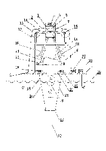
BRIEF DESCRIPTION OF THE DRAWINGS
FIG. 1 is a structural schematic diagram of the present invention;
CA 3050787 2019-07-30
FIG. 2 is a working schematic diagram of a compensation device when the
seawater level rises;
FIG. 3 is a working schematic diagram of the compensation device when the
seawater level descends;
FIG. 4 is a schematic structural diagram of a floating crown block.
In drawings, reference symbols represent the following components: 1-floating
drilling platform; 2-stand; 3-drilling derrick; 4-earring screw; 5-spring; 6-
pressure plate;
7-flating crown block; 8-central sheave; 9-large hook; 10-riser; 11-large hook
lifting
rope; 12-steel wire rope; 13-first connecting rod; 14-second connecting rod;
15-guide
wheel; 16-hydraulic compensation cylinder; 17-annular ring; 18-motor A; 19-
coiling
roller A; 20-pull rope A; 21-motor B; 22-coiling roller B; 23-pull rope B; 24-
energy
accumulator; 25-control valve; 26-motor C; 27-coiling roller C; 28-pipeline;
29-sea
surface.
EMBODIMENTS OF THE INVENTION
DETAILED DESCRIPTION
The present invention will be further described below in conjunction with the
accompanying drawings, and the protection scope of the present invention is
not limited
as follows:
as shown in FIGS. 1 and 4, a passive deep-sea heave compensation device for
ocean platform drilling comprises a floating drilling platform 1, a stand 2
arranged on
the top of the floating drilling platform 1, and a drilling derrick 3 arranged
on the top
of the stand 2, wherein an earring screw 4 and a drilling winch are arranged
on the top
of the floating drilling platform 1 and located on the left side and the right
side of the
stand 2 respectively; a vertical guiding groove is formed inside the drilling
derrick 3; a
vertical spring 5 is fixedly arranged on the top of the guiding groove; a
pressure plate
6 which is located in the guiding groove is fixedly arranged on the bottom of
the spring
5; a floating crown block 7 is slidably mounted in the guiding groove and
located right
below the pressure plate 6; a central sheave 8 whose cylindrical surface is
provided
6
CA 3050787 2019-07-30
with a plurality of trunkings is rotatably mounted in the floating crown block
7; the
heave compensation device further comprises a large hook 9, a riser 10, a
large hook
lifting rope 11, a steel wire rope 12, as well as a displacement compensation
mechanism
1 and a right displacement compensation mechanism II which are arranged on the
left
side and the right side of a stand 2 respectively; the displacement
compensation
mechanism I and the right displacement compensation mechanism II are arranged
in a
left-right symmetrical manner;
the displacement compensation mechanism 1 comprises a first connecting rod 13,
a second connecting rod 14, a guide wheel 15, and a hydraulic compensation
cylinder
16. wherein the lower end of the first connecting rod 13 is hinged to the top
of the stand
2, and the other end of the first connecting rod 13 is hinged to the middle
part of the
guide wheel 15; one end of the second connecting rod 14 is hinged to the
middle part
of the guide wheel 15, and the other end of the second connecting rod 14 is
hinged to
the middle part of the central sheave 8; the hydraulic compensation cylinder
16 is
obliquely arranged to the right upwards; a cylinder barrel of the hydraulic
compensation
cylinder 16 is hinged to the stand 2; a piston rod of the hydraulic
compensation cylinder
16 is hinged to the bottom of the floating crown block 7; the tail end of the
steel wire
rope 12 is fixed on the earring screw 4, and the head end of the steel wire
rope 12
bypasses the guide wheel 15 of the displacement compensation mechanism I and
is then
coiled on the center sheave 8 in multiple coils; subsequently, the head end of
the steel
wire rope 12 bypasses the guide wheel 15 of the displacement compensation
mechanism II and is then fixed on the drilling winch; one end of the large
hook lifting
rope 11 is fixed to the floating crown block 7, and the large hook 9 is fixed
to the other
end of the large hook lifting rope 11; the large hook 9 is located below the
floating
drilling platform 1; the riser 10 is suspended on the large hook 9 and is
fixedly sleeved
with an annular ring 17.
The heave compensation device further comprises a coiling mechanism I and a
coiling mechanism II which are positioned on the left side and the right side
of the
drilling derrick 3 respectively; the coiling mechanism I and the coiling
mechanism II
7
CA 3050787 2019-07-30
are arranged relative to the drilling derrick 3 in a left-right symmetrical
manner; the
coiling mechanism I consists of a motor A 18, a coiling roller A 19 and a pull
rope A
20; the motor A 18 is fixed on the top of the floating drilling platform I; an
output shaft
of the motor A 18 is connected to one end of the coiling roller A 19 via a
coupling; one
end of the pull rope A 20 is fixed to the coiling roller A 19, and the other
end of the pull
rope A20 is welded to the left side of the annular ring 17; the coiling
mechanism II
consists of a motor B 21, a coiling roller B 22 and a pull rope B 23, wherein
the motor
B 21 is fixed to the top of the floating drilling platform I; an output shaft
of the motor
B 21 is connected to one end of the coiling roller B 22 via a coupling; one
end of the
pull rope B 23 is fixed to the coiling roller B 22, and the other end of the
pull rope B23
is welded to the right side of the annular ring 17.
The heave compensation device further comprises an energy accumulator 24 and
a control valve 25, wherein the energy accumulator 24 is arranged on the stand
2; the
control valve 25 is connected to an output port of the energy accumulator 24;
a T-branch
pipe is connected to the other end of the control valve; two ports of the T-
branch pipe
are communicated with rodless cavities of two hydraulic compensation cylinders
16 via
pipelines 28.
The drilling winch comprises a motor C 26, a coiling roller C 27, and a speed
reducer, wherein the motor C 26 and the speed reducer are respectively
arranged on the
top of the floating drilling platform 1; an output shaft of the motor C 26 is
connected to
an input shaft of the speed reducer via a coupling; a coiling roller C 27 is
connected to
an output shaft of the speed reducer via a coupling.
The head end of the steel wire rope 12 bypasses the guide wheel 15 of the
displacement compensation mechanism II and is then fixed on the coiling roller
C27.
The floating drilling platform 1 is provided with a through groove which is
located right
below the drilling derrick 3. The large hook lifting rope 11 penetrates
through the
through groove.
The working process of the present invention is as follows: as shown in FIG.
1,
when the riser 10 is lowered, hydraulic oil in the rodless cavity of the
hydraulic
8
CA 3050787 2019-07-30
compensation cylinder 16 is pumped out, and a piston rod of the hydraulic
compensation cylinder 16 retracts. The floating crown block 7 moves downward
along
the guiding groove, and the riser 10 suspended on the large hook 9 at this
moment enters
the sea bottom. During the descending process, if the riser 10 is observed to
be tilted to
the left, the worker on the floating drilling platform 1 turns on the motor
B21. The
motor B21 drives the coiling roller B22 to rotate, the pull rope B23 is
gradually wound
up on the coiling roller B22 and applies a rightward pulling force to the
annular ring 17,
thereby further pulling the riser 10 to the right. When the riser 10 is in a
vertical state,
the motor B 21 is turned off If the riser 10 is observed to be tilted to the
right, the
worker on the floating drilling platform 1 turns on the motor Al 8. The motor
Al8 drives
the coiling roller A19 to rotate, the pull rope A20 is gradually wound up on
the coiling
roller Al9 and applies a leftward pulling force to the annular ring 17,
thereby further
pulling the riser 10 to the left. When the riser 10 is in a vertical state,
the motor Al8 is
turned off. Therefore, the device ensures a vertical drop of the riser 10, and
further
ensures the safety of the subsequently lowered drill string and the drilled
drill bit.
During the development of deep-sea oil and gas, due to complex and variable
environments of the working sea area, the heave movement state of the floating
drilling
platform 1 changes rapidly, and the smooth operation of the drilling operation
is greatly
affected. However, the device is capable of compensating for the vertical
displacement
of the riser 10 to further ensure smooth drilling. As shown in FIG. 2, when
the floating
drilling platform 1 rises with the waves, the load of the large hook 9
increases, and the
piston rod in the hydraulic compensation cylinder 16 moves upward, causing gas
in the
energy accumulator 24 to expand. The floating crown block 7 moves upward along
the
guiding groove relative to the drilling derrick 3, and the floating crown
block 7 presses
against the pressure plate 6, and the pressure plate 6 then compresses the
spring 5.
Meanwhile, one end of each of the two second connecting rods 14 moves upward
with
the floating crown block 7, and the second connecting rod 14 drives the first
connecting
rod 13 to expand outward, further driving the guide wheel 15 to tension the
steel wire
rope 12 outwards, and the steel wire rope 12 applies a downward force to the
guide
9
CA 3050787 2019-07-30
wheel 15. Meanwhile, the pressure plate 6 is also pressed against the floating
crown
block 7 under the restoring force of the spring 5. Under these two forces, the
rapid reset
of the floating crown block 7 is ensured, thereby compensating for the
displacement of
the large hook and the drill string due to the rise of the floating drilling
platform 1, to
ensure that the displacement of the riser in the vertical direction is always
unchanged.
As shown in FIG. 3, when the floating drilling platform 1 descends with the
waves, the
load of the large hook 9 is reduced, and the piston rod in the hydraulic
compensation
cylinder 16 is moved downwards, so that the gas in the energy accumulator 24
is
compressed. The floating crown block 7 moves downward along the guiding groove
relative to the drilling derrick 3. Meanwhile, one end of each of the two
second
connecting rods 14 moves downwards with the floating crown block 7, and the
second
connecting rod 14 drives the first connecting rod 13 to contract inwards, and
the steel
wire rope 12 is in a relaxed state. At this time, the compressed gas in the
energy
accumulator 24 has a tendency to drive the piston rod of the hydraulic
compensation
cylinder 16 to extend upwards. After the piston rod extends, the floating
crown block 7
is reset, thereby compensating for the displacement of the large hook and the
drill string
due to the lowering of the floating drilling platform 1, to ensure that the
displacement
of the riser in the vertical direction is always unchanged. Therefore, the
device has the
characteristics of high compensation efficiency, high system response speed,
and
response sensitivity, does not require external hydraulic components to
participate, and
ensuring the smooth drilling of the drill bit.
CA 3050787 2019-07-30