Sélection de la langue

Search

Sommaire du brevet 3050849 

Énoncé de désistement de responsabilité concernant l'information provenant de tiers

Une partie des informations de ce site Web a été fournie par des sources externes. Le gouvernement du Canada n'assume aucune responsabilité concernant la précision, l'actualité ou la fiabilité des informations fournies par les sources externes. Les utilisateurs qui désirent employer cette information devraient consulter directement la source des informations. Le contenu fourni par les sources externes n'est pas assujetti aux exigences sur les langues officielles, la protection des renseignements personnels et l'accessibilité.

Disponibilité de l'Abrégé et des Revendications

L'apparition de différences dans le texte et l'image des Revendications et de l'Abrégé dépend du moment auquel le document est publié. Les textes des Revendications et de l'Abrégé sont affichés :

  • lorsque la demande peut être examinée par le public;
  • lorsque le brevet est émis (délivrance).
(12) Brevet: (11) CA 3050849
(54) Titre français: SYSTEME DE COMMANDE DESTINE AU FREIN DE STATIONNEMENT AUTOMATIQUE D'UN VEHICULE FERROVIAIRE
(54) Titre anglais: CONTROL SYSTEM FOR AUTOMATIC PARKING BRAKE OF RAIL VEHICLE
Statut: Accordé et délivré
Données bibliographiques
(51) Classification internationale des brevets (CIB):
  • B60T 15/02 (2006.01)
  • B60T 17/08 (2006.01)
  • B60T 17/16 (2006.01)
  • F15B 15/26 (2006.01)
(72) Inventeurs :
  • CALL, DERICK (Etats-Unis d'Amérique)
(73) Titulaires :
  • NEW YORK AIR BRAKE LLC
(71) Demandeurs :
  • NEW YORK AIR BRAKE LLC (Etats-Unis d'Amérique)
(74) Agent: BORDEN LADNER GERVAIS LLP
(74) Co-agent:
(45) Délivré: 2019-10-22
(86) Date de dépôt PCT: 2017-02-07
(87) Mise à la disponibilité du public: 2018-08-16
Requête d'examen: 2019-07-18
Licence disponible: S.O.
Cédé au domaine public: S.O.
(25) Langue des documents déposés: Anglais

Traité de coopération en matière de brevets (PCT): Oui
(86) Numéro de la demande PCT: PCT/US2017/016835
(87) Numéro de publication internationale PCT: US2017016835
(85) Entrée nationale: 2019-07-18

(30) Données de priorité de la demande:
Numéro de la demande Pays / territoire Date
15/426,619 (Etats-Unis d'Amérique) 2017-02-07

Abrégés

Abrégé français

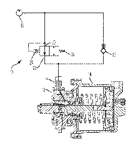
L'invention concerne une soupape de commande (10) destinée à un frein de stationnement automatique présentant une entrée (20) pour le couplage à une source d'une pression de conduite de frein, une sortie (22) pour le couplage à une entrée de commande du frein de stationnement automatique et un pilote (24) pour le couplage à la source de pression de conduite de frein. La soupape de commande est mobile entre une première position dans laquelle l'entrée est en communication avec la sortie et une seconde position dans laquelle l'entrée et la sortie sont isolées l'une de l'autre en réponse à une quantité prédéterminée de pression de conduite de frein au niveau du pilote. La soupape de commande comprend un ressort sollicitant la soupape de commande dans la première position.


Abrégé anglais

A control valve (10) for an automatic parking brake having an inlet (20) for coupling to a source a brake pipe pressure, an outlet (22) for coupling to a control inlet of the automatic parking brake and a pilot (24) for coupling to the source of brake pipe pressure. The control valve is moveable between a first position where the inlet is in communication with the outlet and a second position where the inlet and the outlet are isolated from each other in response to a predetermined amount of brake pipe pressure at the pilot. The control valve includes a spring biasing the control valve into the first position.

Revendications

Note : Les revendications sont présentées dans la langue officielle dans laquelle elles ont été soumises.


CLAIMS:
1. A system for controlling an automatic parking brake, comprising:
a control valve having an inlet for coupling to a source of brake pipe
pressure, an
outlet for coupling to a control inlet of the automatic parking brake, and a
pilot directly
coupled to the source of brake pipe pressure, wherein the control valve is
moveable between a
first position where the inlet is in communication with the outlet and a
second position where
the inlet and the outlet are isolated from each other in response to a
predetermined amount of
brake pipe pressure at the pilot; and
a check valve having a cracking pressure and coupled to the source of brake
pipe
pressure and the automatic parking brake control inlet, wherein the check
valve is in parallel
with the control valve.
2. The system of claim 1, wherein the control valve includes a spring
biasing the control
valve into the second position.
3. The system of claim 2, wherein the predetermined amount of brake pipe
pressure
required to move the control valve from the first position into the second
position is between
50 and 60 psi.
4. The system of claim 3, wherein the check valve has a cracking pressure
of less than
two psi.
5. The system of claim 4, further comprising a brake cylinder having the
automatic
parking brake installed therein, wherein the automatic parking brake is
coupled to the outlet of
the control valve by the control inlet.
6. The system of claim 5, further comprises a brake pipe coupled to the
pilot and
providing the source of brake pipe pressure.

7. A method of controlling an automatic parking brake, comprising the steps
of:
providing a control valve having an inlet coupled to a source a brake pipe
pressure, an
outlet coupled to a control inlet of the automatic parking brake and a pilot
directly coupled to
the source of brake pipe pressure;
moving the control valve into a first position that isolates the inlet from
the outlet
when the brake pipe pressure is above a predetermined amount;
moving the control valve into a second position that coupled the inlet and the
outlet
when the brake pipe pressure is above the predetermined amount; and
providing a check valve having a cracking pressure between the source of brake
pipe
pressure and the control inlet of the automatic parking brake, wherein the
check valve is in
parallel with the control valve.
8. The method of claim 7, wherein the control valves includes a spring
biasing the
control valve into the second position.
9. The method of claim 8, wherein the predetermined amount of brake pipe
pressure is
between 50 and 60 psi.
10. The method of claim 9, wherein the cracking pressure is less than two
psi.
11. The method of claim 9, further comprising the step of coupling the
control valve to a
brake cylinder having the automatic parking brake installed therein by
coupling the outlet of
the control valve to the control inlet of the automatic parking brake.
12. The method of claim 11, further comprising the step of attaching a
brake pipe to the
pilot.
6

Description

Note : Les descriptions sont présentées dans la langue officielle dans laquelle elles ont été soumises.


CA 03050849 2019-07-18
WO 2018/147830 PCT/US2017/016835
TITLE
CONTROL SYSTEM FOR AUTOMATIC PARKING BRAKE OF RAIL VEHICLE
BACKGROUND OF THE INVENTION
1. FIELD OF THE INVENTION
[0001] The present invention relates to automatic parking brakes for rail
vehicles and,
more specifically, to a control valve for controlling the release of automatic
parking brakes.
2. DESCRIPTION OF THE RELATED ART
[0002] In order to avoid having to manually apply the brake on each rail
car in a train to
accomplish a parking brake function, automatic parking brakes having been
developed that
automatically retain the brake cylinder in a fully applied position if the
brake pipe pressure is
exhausted below a predetermined threshold. For example, a conventional parking
brake system
is the Parkloc system available from New York Air Brake, LLC of Watertown,
New York,
which is additionally described in U.S. Patent Nos. 7,163,090 and 7,377,370.
The Parkloc
system uses a pneumatically controlled, mechanical locking mechanism to lock
the air brake
cylinder in the applied, loaded state. As a result, even if the air brake
cylinder subsequently
leaks away due to a long parking duration, the brakes are mechanically held in
the applied
position.
[0003] The latching mechanism in the Parkloc system is piloted by brake
pipe pressure
and is arranged to lock when brake pipe pressure drops below a certain amount
and unlock when
the brake pipe exceeds a certain amount. The pressure at which Parkloc system
releases the
brakes is a function of the amount of force that the Parkloc system is
retaining. More
specifically, the more force that is being applied by the brake cylinder, the
more friction there is
between the structure of the locking mechanism and the brake cylinder. As a
result, more brake
pipe pressure is required to disengage the locking mechanism from the brake
cylinder. For
example, if the train was operating with a brake pipe (BP) pressure of 70 psi
and the BP was
vented to zero at service rate, the resulting brake cylinder pressure would be
about 50 psi and
represents the lowest amount of force that is retained. If a train was
operating at a BP pressure of
110 psi and the BP vented to zero at an emergency rate, the resulting brake
cylinder pressure
would be about 94 psi. If the hand brake was then applied on top of the
emergency brake
application, the highest amount of retained force would result. The difference
between the
lowest amount of retained force and the highest amount of retained force is
significant and
1

CA 03050849 2019-07-18
WO 2018/147830 PCT/US2017/016835
causes a large variation in the BP pressure at which the Parkloc system will
release. As a
result, when BP pressure is restored, all parking brakes will not necessarily
release at the same
time, which is an issue if the train is parked on a grade. Accordingly, there
is a need for an
improvement to an automatic parking brake system, such as the Parkloc system
or any other,
that will ensure a more consistent and reliable release.
BRIEF SUMMARY OF THE INVENTION
[0004] The present invention ensures a more consistent and reliable
release of an
automatic parking brake with a control valve having an inlet for coupling to a
source a brake
pipe pressure, an outlet for coupling to a control inlet of the automatic
parking brake and a pilot
for coupling to the source of brake pipe pressure, wherein the control valve
is moveable between
a first position where the inlet is in communication with the outlet and a
second position where
the inlet and the outlet are isolated from each other in response to a
predetermined amount of
brake pipe pressure at the pilot. The control valve includes a spring biasing
the control valve
into the first position. The predetermined amount of brake pipe pressure
required to move the
control valve from the first position into the second position is preferably
between 50 and 60 psi.
A check valve having a cracking pressure of less than two psi may be coupled
to the source of
brake pipe pressure and the automatic parking brake control inlet in parallel
with the control
valve.
[0005] The present invention also includes a method of controlling an
automatic parking
brake, comprising the steps of providing a control valve having an inlet
coupled to a source a
brake pipe pressure, an outlet coupled to a control inlet of the automatic
parking brake and a pilot
coupled to the source of brake pipe pressure, moving the control valve into a
first position that
isolates the inlet from the outlet when the brake pipe pressure is above a
predetermined amount;
and moving the control valve into a second position the coupled the inlet and
the outlet when the
brake pipe pressure is above the predetermined amount. The control valve
includes a spring
biasing the control valve into the first position against any pressure at the
pilot. The
predetermined amount of brake pipe pressure is preferably between 50 and 60
psi. The method
may also include the step of providing a check valve having a cracking
pressure of less than two
psi between the source of brake pipe pressure and the control inlet of the
automatic parking brake
in parallel with the control valve.
2

CA 03050849 2019-07-18
WO 2018/147830 PCT/US2017/016835
BRIEF DESCRIPTION OF THE SEVERAL VIEWS OF THE DRAWING(S)
[0006] The present invention will be more fully understood and appreciated
by reading
the following Detailed Description in conjunction with the accompanying
drawings, in which:
[0007] FIG. 1 is a schematic of a control valve for an automatic parking
brake according
to the present invention in a first position; and
[0008] FIG. 2 is a schematic of a control valve for an automatic parking
brake according
to the present invention in a second position.
DETAILED DESCRIPTION OF THE INVENTION
[0009] Referring to the figures, wherein like numerals refer to like parts
throughout, there
is seen in FIG. 1 a control valve 10 for use with an automatic parking brake
12 that is coupled to
a brake cylinder 14 for retaining the brake cylinder 14 in the brakes applied
position when a train
is to be parked, such as the Parkloc system. Control valve 10 is positioned
between the source
of BP pressure 16, such as the brake pipe, that is used to control the
automatic parking brake 12
and the control inlet 18 of automatic parking brake 12 that receives brake
pipe pressure so that
the parking brake 12 can respond thereto. Control valve 10 includes an inlet
20 in
communication with the source of BP pressure 16 and an outlet 22 in
communication with the
BP pressure inlet 18 of automatic parking brake 12. Control valve 10 is
moveable between a
first position where inlet 20 is connected to outlet 22, and a second position
where inlet 20 and
outlet 22 are isolated from each other. Control valve 10 further includes a
pilot 24 coupled to a
source of BP pressure 16. Pilot 24 may be coupled to sources of pressure in
addition to BP
pressure 16, such as the emergency or auxiliary reservoir pressures (or
combinations thereof), for
additional functionality like delaying the release on the first railcar in a
train due to the delay in
charging of the various reservoirs at the rear of a train.
[0010] Pilot 24 is configured to urge control valve 10 from the first
position to the second
position against a biasing force, such as a spring 26. Spring 26 is configured
to provide a
predetermined amount of biasing force so that control valve will shuttle
between the first and
second positions when BP pressure 16 at pilot 24 is between 50 and 60 psi. A
check valve 28
with a cracking pressure of less than 2 psi is positioned in parallel to
control valve 10 between
the source of BP pressure 16 and the BP pressure control inlet 18 of automatic
parking brake 12.
FIG. 1 illustrates control valve 10 in a released state, such as when BP
pressure is fully charged,
i.e., 90 psi in most locations. It should be recognized that the triggering
pressures may be varied
3

CA 03050849 2019-07-18
WO 2018/147830 PCT/US2017/016835
according to the system to adjust the timing of the locking and unlocking, or
to account for the
use of additional sources of pressure connected to pilot 24.
[0011] As seen in FIG. 2, when BP pressure is vented to, for example, 10
psi, control
valve 10 will shuttle to the second position, thereby isolating the BP
pressure inlet 18 of
automatic parking brake 12 from the source of BP pressure 16. In the absence
of BP pressure at
inlet 18, inlet 18 will vent through check valve 28 so that the pressure drops
to below 2 psi (as
determined by the cracking pressure of check valve 28. As a result of the loss
of pressure, the
locking mechanism of automatic parking brake 12 will engage and lock brake
cylinder 14. When
BP pressure is recharged, control valve 10 will not shuttle back to the first
position until the BP
pressure at pilot 24 reaches the predetermined level set by spring 26, e.g.,
between 50 and 60 psi.
As a result, the charging BP pressure remains isolated from automatic parking
brake 12 until this
point as no BP pressure is provided to the BP pressure inlet 18 of automatic
parking brake 12
until control valve 10 returns to the first position. Automatic parking brake
12 will thus remain
engaged until the BP pressure surpasses the predetermined level set by spring
26 and control
valve 10 is shuttles to the first position as shown in FIG. 1. Thus, once BP
pressure reaches the
predetermined level, such as 50-60 psi, control valve 10 move into the first
position to connect
inlet 20 with outlet 22, thereby allowing BP pressure to flow to BP pressure
control inlet 18 of
automatic parking brake 12. As a result, the locking mechanism will be
released of automatic
parking brake 12. It should be recognized that a train having rail cars
equipped with control
valve 10 according to the present invention will release the locking mechanism
of each parking
brake of each rail car simultaneously as all automatic parking brakes 12 will
not release until the
predetermined level of BP pressure is reaches such that each control valve 10
of every rail car
shuttles to the first position.
[0012] Control valve 10 may be used with any automatic parking brake 12
that engages
in the absence of brake pipe pressure and disengages in response to recharging
of the brake pipe,
including the Parkloc system. Control valve 10 may be used with any automatic
parking brake
12, including those used on ABU type and truck mounted brake cylinders.
4

Dessin représentatif
Une figure unique qui représente un dessin illustrant l'invention.
États administratifs

2024-08-01 : Dans le cadre de la transition vers les Brevets de nouvelle génération (BNG), la base de données sur les brevets canadiens (BDBC) contient désormais un Historique d'événement plus détaillé, qui reproduit le Journal des événements de notre nouvelle solution interne.

Veuillez noter que les événements débutant par « Inactive : » se réfèrent à des événements qui ne sont plus utilisés dans notre nouvelle solution interne.

Pour une meilleure compréhension de l'état de la demande ou brevet qui figure sur cette page, la rubrique Mise en garde , et les descriptions de Brevet , Historique d'événement , Taxes périodiques et Historique des paiements devraient être consultées.

Historique d'événement

Description Date
Représentant commun nommé 2019-10-30
Accordé par délivrance 2019-10-22
Inactive : Page couverture publiée 2019-10-21
Inactive : Taxe finale reçue 2019-09-12
Préoctroi 2019-09-12
Lettre envoyée 2019-08-27
Un avis d'acceptation est envoyé 2019-08-27
Inactive : Page couverture publiée 2019-08-16
Inactive : Q2 réussi 2019-08-13
Inactive : Approuvée aux fins d'acceptation (AFA) 2019-08-13
Inactive : Acc. récept. de l'entrée phase nat. - RE 2019-08-05
Lettre envoyée 2019-08-02
Demande reçue - PCT 2019-08-02
Inactive : CIB en 1re position 2019-08-02
Inactive : CIB attribuée 2019-08-02
Lettre envoyée 2019-08-02
Avancement de l'examen jugé conforme - PPH 2019-07-18
Exigences pour une requête d'examen - jugée conforme 2019-07-18
Modification reçue - modification volontaire 2019-07-18
Exigences pour l'entrée dans la phase nationale - jugée conforme 2019-07-18
Avancement de l'examen demandé - PPH 2019-07-18
Toutes les exigences pour l'examen - jugée conforme 2019-07-18
Demande publiée (accessible au public) 2018-08-16

Historique d'abandonnement

Il n'y a pas d'historique d'abandonnement

Taxes périodiques

Le dernier paiement a été reçu le 2019-07-18

Avis : Si le paiement en totalité n'a pas été reçu au plus tard à la date indiquée, une taxe supplémentaire peut être imposée, soit une des taxes suivantes :

  • taxe de rétablissement ;
  • taxe pour paiement en souffrance ; ou
  • taxe additionnelle pour le renversement d'une péremption réputée.

Les taxes sur les brevets sont ajustées au 1er janvier de chaque année. Les montants ci-dessus sont les montants actuels s'ils sont reçus au plus tard le 31 décembre de l'année en cours.
Veuillez vous référer à la page web des taxes sur les brevets de l'OPIC pour voir tous les montants actuels des taxes.

Historique des taxes

Type de taxes Anniversaire Échéance Date payée
TM (demande, 2e anniv.) - générale 02 2019-02-07 2019-07-18
Enregistrement d'un document 2019-07-18
Requête d'examen - générale 2019-07-18
Taxe nationale de base - générale 2019-07-18
Taxe finale - générale 2019-09-12
TM (brevet, 3e anniv.) - générale 2020-02-07 2020-01-31
TM (brevet, 4e anniv.) - générale 2021-02-08 2021-01-29
TM (brevet, 5e anniv.) - générale 2022-02-07 2022-01-28
TM (brevet, 6e anniv.) - générale 2023-02-07 2023-02-03
TM (brevet, 7e anniv.) - générale 2024-02-07 2024-02-02
Titulaires au dossier

Les titulaires actuels et antérieures au dossier sont affichés en ordre alphabétique.

Titulaires actuels au dossier
NEW YORK AIR BRAKE LLC
Titulaires antérieures au dossier
DERICK CALL
Les propriétaires antérieurs qui ne figurent pas dans la liste des « Propriétaires au dossier » apparaîtront dans d'autres documents au dossier.
Documents

Pour visionner les fichiers sélectionnés, entrer le code reCAPTCHA :


Pour visualiser une image, cliquer sur un lien dans la colonne description du document (Temporairement non-disponible). Pour télécharger l'image (les images), cliquer l'une ou plusieurs cases à cocher dans la première colonne et ensuite cliquer sur le bouton "Télécharger sélection en format PDF (archive Zip)" ou le bouton "Télécharger sélection (en un fichier PDF fusionné)".

Liste des documents de brevet publiés et non publiés sur la BDBC .

Si vous avez des difficultés à accéder au contenu, veuillez communiquer avec le Centre de services à la clientèle au 1-866-997-1936, ou envoyer un courriel au Centre de service à la clientèle de l'OPIC.

({010=Tous les documents, 020=Au moment du dépôt, 030=Au moment de la mise à la disponibilité du public, 040=À la délivrance, 050=Examen, 060=Correspondance reçue, 070=Divers, 080=Correspondance envoyée, 090=Paiement})


Description du
Document 
Date
(aaaa-mm-jj) 
Nombre de pages   Taille de l'image (Ko) 
Abrégé 2019-07-17 1 72
Description 2019-07-17 4 221
Revendications 2019-07-17 2 64
Dessins 2019-07-17 2 70
Dessin représentatif 2019-07-17 1 33
Revendications 2019-07-18 2 67
Dessin représentatif 2019-10-06 1 20
Paiement de taxe périodique 2024-02-01 46 1 896
Courtoisie - Certificat d'enregistrement (document(s) connexe(s)) 2019-08-01 1 106
Accusé de réception de la requête d'examen 2019-08-01 1 175
Avis du commissaire - Demande jugée acceptable 2019-08-26 1 163
Avis d'entree dans la phase nationale 2019-08-04 1 202
Traité de coopération en matière de brevets (PCT) 2019-07-17 6 450
Déclaration 2019-07-17 1 36
Rapport de recherche internationale 2019-07-17 2 70
Demande d'entrée en phase nationale 2019-07-17 6 163
Documents justificatifs PPH 2019-07-17 3 162
Requête ATDB (PPH) 2019-07-17 7 245
Taxe finale 2019-09-11 1 32