Note : Les descriptions sont présentées dans la langue officielle dans laquelle elles ont été soumises.
I
INSTALLATION TOOL FOR A ROCK BOLT
BACKGROUND OF THE INVENTION
[0001] This invention relates to a rock bolt installation tool for use in the
installation
of a rock bolt assembly into a predrilled rock hole.
[0002] In a typical rock bolt installation, a leading end of a rock bolt is at
least
partially inserted into a rock hole and a trailing end of the rock bolt is
engaged with a
complementary formation on installation equipment, such as a drill rig,
jackleg drill
or bolter (hereinafter referred to as a drill rig), in order to install the
rock bolt in the
rock hole.
[0003] To increase stability and to ensure that the rock bolt is maintained in
axial
alignment with the rock hole, the drill rig is often provided with a prop
which
engages with a face of the rock mass, into which the rock bolt is to be
inserted, and
onto which several guide rings are engaged, longitudinally spaced. It is
through
these rings that the rock bolt passes to guide the bolt into the hole without
bending.
Often, these guide rigs are removed from the drill rig to remove interference
with the
passage of a rock bolt with an associated faceplate or the like. Without these
guiding formations, the percussive force of the drill rig concentrated on the
trailing
end of the rock bolt causes the rock bolt to bend during insertion which
compromises the rock bolt installation.
CA 3051542 2019-08-07
2
[0004] A further problem arises when a load indicator is included in the rock
bolt
assembly, interposed between the nut and spherical seat.
[0005] During mechanised installation, the load indicator is pushed against a
spherical seat which, in turn, is forced against a faceplate, when the
faceplate
bottoms out against the rock wall. An operator of the drill rig cannot avoid
such a
situation as he cannot judge or accurately control the installation depth of
the bolt.
He will continue to drive the bolt into the hole until the bolt stops moving
forwardly.
[0006] As a result, the load indicator will be progressively squashed between
a
trailing formation, such as a nut, and the spherical seat which action can
cause
premature collapse of the spherical seat as a result of the percussive force
of
installation rather than a rotationally applied pre-tensioning force. The
collapse of
the load indicator in this manner results in a false indication that the rock
bolt has
been sufficiently pretensioned.
[0007] The invention at least partially sources the aforementioned problem.
SUMMARY OF INVENTION
[0008]The invention provides a rock bolt installation tool for use in the
installation of
a rock bolt assembly into a predrilled rock hole, which tool includes a drive
shaft
having a proximal end, which is adapted to engage with a drill rig, and a
distal end,
a socket in the distal end that includes a first containment portion, of a
first
diameter, which has a base and a second containment portion, of a second
diameter, between the first containment portion and the second end, wherein
the
CA 3051542 2019-08-07
3
first containment portion is adapted to receive a nut of the rock bolt
assembly,
wherein the second containment portion is adapted to receive a load-indicator
of the
rock bolt assembly, and wherein the base and the second end are adapted to
provide surfaces against which the nut and a spherical seat of the rock bolt
assembly respectively engage to be driven into the rock hole.
[0009]The second diameter of the second containment portion may be larger than
the first diameter of the first containment portion.
[0010]The distal end of the drive shaft may be adapted with a threaded male or
female section.
[0011]The first portion may be adapted in a hex shape to receive a hex shaped
nut.
[0012]The drive shaft may have a conduit which runs the length of the shaft
opening at the proximal end and opening through the base, into the socket.
BRIEF DESCRIPTION OF THE DRAWINGS
[0013] The invention is further described by way of examples with reference to
the
accompanying drawings in which:
Figure 1 is a view in perspective of a rock bolt installation tool in
accordance with
the invention;
Figure 2 is a view in elevation of the rock bolt installation tool of Figure
1;
Figure 3 is a view in longitudinal section of the tool of Figure 1
illustrating a trailing
end of a rock bolt assembly engaged with the tool;
CA 3051542 2019-08-07
4
Figure 4 schematically illustrates an installation system for a rock bolt
which system
includes the rock bolt installation tool;
Figure 5 illustrates a longitudinal section through an end of the rock bolt
installation
tool, with a trailing end of a rock bolt engaged with the tool, in a first
configuration;
and
Figure 6 illustrates a longitudinal section through an end of the rock bolt
installation
tool, with a trailing end of a rock bolt engaged with the tool, in a second
configuration.
DESCRIPTION OF PREFERRED EMBODIMENTS
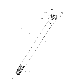
[0014] Figure 1 illustrates a rock bolt installation tool 10 according to the
invention.
The tool 10 includes a cylindrical drive shaft 12 having a proximal end 14 and
a
distal end 16.
[0015] The proximal end 14 of the shaft 12 is adapted to engage with a drill
rig 18
(see Figure 4). The proximal end can be adapted either with a male or female
threaded formation that engages with a complementary formation on the drive
means 20 of the drill rig. In this example, the proximal end has a male
threaded
formation 22.
[0016] The shaft has a conduit 24 which runs the length of the shaft (see
Figure 3),
opening at each end (14, 16). The conduit is divided into three discrete
sections,
each adapted to provide a particular function. However, the common function is
to
CA 3051542 2019-08-07
5
provide a conduit for the passage of a fluid input, such as an adhesive
material or a
flushing medium, input from the proximal end 14.
[0017] The first section, a bore 26, extends between the proximal end 14 and
an
intermediate point 28. The bore is of a first diameter. The second section, a
rock
bolt receptacle 30, extends between the intermediate point 28 and a stepped
annular first drive surface 32. The receptacle is of a second diameter, larger
than
the first diameter. The third section, a recess or socket 34, extends between
the
drive surface and the distal end 16. The recess has a variable diameter which
exceeds both the first and second diameter.
[0018] Exteriorly, along a distal end portion 36 of the drive shaft 12, which
ends at
the distal end 16, the shaft is circumferentially enlarged to accommodate the
internally larger diameter of the recess 34 contained within this portion.
[0019] The recess 34, in turn, is divided into parts: an outer load indicator
receiving
portion 38 (see Figure 5) and a deeper set nut receiving portion 40 (see
Figure 6).
The base of the nut receiving portion is the stepped annular drive surface 32.
At an
interface 42 between the nut receiving portion 40 and the load indicator
receiving
portion 38, the inner wall of the recess opens out to provide the load
indicator
receiving portion with a circumferentially larger space relatively to portion
40. This
feature 42 is illustrated in Figure 1.
[0020] The tool 10 is used to install a rock bolt assembly 44 into a pre-
drilled rock
hole 46. The assembly 44 typically includes a rock bolt 48 which extends
between
CA 3051542 2019-08-07
6
a leading end (not shown) and a trailing end 50. The rock bolt will be
inserted into a
pre-drilled rock hole, by the tool, leading end first. Towards the trailing
end 50 the
rock bolt 48 carries a domed face plate 52, a spherical seat 54 and a load
indicator
56. A hexagonal nut 58, is threadedly engaged with a threaded end section 60
of
the rock bolt 48, trailing the load indicator. The spherical seat is disposed
between
the domed faceplate and the load indicator.
[0021] In use, the rock bolt assembly 44 is engaged with the installation tool
10 by
inserting the threaded end section 60 of the rock bolt 48 into the shaft 12,
through
the recess 34 and extending into the receptacle 30. Ingress of the rock bolt
is
stopped when the nut 58 contacts the annular drive surface 32 at the base of
the
receptacle.
[0022] The nut receiving portion 40 of the receptacle will be complementarily
shaped to receive the nut in snug fit, with the recess being deep enough to
contain
the nut. The hex shape of this portion is partially illustrated in Figure 1.
[0023] With the nut received in recess 34, the diametrically larger load
indicator 56
is found in the adjacent load indicator receiving portion 38. This portion has
enough
depth so that, with the spherical seat 54 outside of the recess, abutting the
distal
end 16, the load indicator is spaced either from the spherical seat or the
nut, the
beneficial effect of which will be described below.
[0024] With the tool 10 now engaged with the drill rig 18 and with the end
section
60 of the rock bolt 48, the bolt is inserted into the rock hole 46 as shown in
Figure 4,
CA 3051542 2019-08-07
7
leading end first. During insertion, the nut 42 is spaced from the load
indicator 56.
This spacing is best illustrated in Figure 5.
[0025] As the assembly has a friction element, being a sleeve 62, the rock
bolt 48
needs to be driven into the rock hole 46 by the application of a percussive
force.
This force is applied by the drive means 20 of the drill rig 18 onto the
installation
tool. This force is transmitted to the rock bolt, via the nut, by the drive
surface 32.
[0026] As the shaft of the rock bolt 46 is driven incrementally forward, into
the rock
hole 46, by the percussive force on the nut 58, eventually the faceplate 52
and the
trailing spherical seat 54, will abut the rock wall surrounding the rock hole,
pushed
along by engagement of the spherical seat with the distal end 16 of the shaft
12
(hereinafter called the second drive surface).
[0027] In this position, the faceplate is forced against the rock face, prior
to the
rock bolt assembly being anchored in the rock hole in pre-load support of the
rock
face, by the force imposed on the nut and the spherical seat, by the first and
the
second drive seats (32, 16) respectively. This is illustrated in Figure 5 with
the
forces represented directionally and locationally as arrows.
[0028] Once the bolt is fully driven into the rock hole, with the bolt having
bottomed
out, no longer advancing further into the hole, an operator of the drill rig
operates
the drive means 20 to discontinue applying an axial drive force and to now
apply a
rotational drive force on the nut 58. The internal hex shape of the nut
receiving
CA 3051542 2019-08-07
8
portion 40, now acting as a socket wrench, ensures that this driving force is
efficiently applied to the nut.
[0029] As the nut 58 is rotated in this manner, the nut advances on the
threads of
the threaded end section 60 of the rock bolt 48, pulling away from the drive
surface
32 and advancing towards the load indicator 56 until it makes contact is made
with
the indicator as illustrated in Figure 6.
[0030] Further rotation and advancement of the nut 58 causes the nut to
compress
the load indicator between it and the spherical seat 54, until the indicator
collapses
as designed, to indicate that nut induced pretension of the rock bolt assembly
has
been achieved to a desired level. Here, the compressive force experienced by
the
load indicator is as a result of the nut turning on the threads of the end
section 60 of
the bolt in pretension of the bolt and not as a result of the percussive
forces during
installation.
[0031] With the clearance height of the load indicator receiving portion 38 of
the
recess 34 being taller than the height of the load indicator 56, the
installation tool 10
can transmit this percussive force directly to the spherical seat 54 and the
nut 58
without the tool being able to apply a load directly on the load indicator 56,
preventing the load indicator from being prematurely squashed. In other words,
the
tool provides a spacing within which the load indicator is sheltered from the
percussive force being applied, through the tool, to the spherical seat of the
nut
installation forces, ensuring that the load indicator can only collapse as a
consequence of preloading the rock bolt in tension within the rock hole.
CA 3051542 2019-08-07
9
[0032] The distal end 16 of the shaft 12, preferably, is formed with turret
formations
64. Between a pair of turret formations and the spherical seat 54, a space 66
is
provided to allow debris, which accumulates within the tool 10 during
insertion of the
rock bolt assembly, to be flushed from the tool by a flushing medium
channelled
through the conduit.
CA 3051542 2019-08-07