Note : Les descriptions sont présentées dans la langue officielle dans laquelle elles ont été soumises.
CA 03052260 2019-07-31
WO 2018/144420 PCT/US2018/015852
FOOTBALL HELMET
CROSS REFERENCE TO RELATED APPLICATIONS
This application claims the benefit of U.S. Provisional Patent Application No.
62/452,577 filed January 31, 2017, which is hereby incorporated by reference
in its
.. entirety.
FIELD OF THE INVENTION
The present invention relates to helmets and, in particular, to football
helmets.
BACKGROUND OF THE INVENTION
In recent years, there has been a significant amount of research into the
health
.. risks associated with repetitive head trauma. In the game of American
football
("football"), players are subjected to player-to-player contact and it is not
uncommon for
a player's head to strike the ground or another player. To prevent injuries to
the head and
face, football players wear a helmet with a hard shell, internal padding and a
wire face
guard. While the football helmets in the prior art generally protect players
from broken
bones and abrasions in their head and face, they are inadequate at protecting
players from
internal injuries, specifically injuries to the brain.
Studies have indicated that football players are susceptible to developing
chronic
traumatic encephalopathy ("CTE"), which is a degenerative disease that has
been
attributed to repetitive concussions or subconcussive impacts to the brain.
Instead of
.. preventing the concussions and subconcussive impacts that are theorized to
cause CTE,
the football helmets in the prior art can exacerbate trauma to the brain in
certain impacts.
For instance, when football players have head-to-head contact, the hard shell
of prior art
football helmets create a nearly elastic collision where the kinetic energy of
the two
- 1 -
CA 03052260 2019-07-31
WO 2018/144420 PCT/US2018/015852
helmets before the collision is nearly equal to their kinetic energy after the
collision.
This effect is similar to a first moving pool ball hitting a second stationary
pool ball ¨
after the impact, the first ball becomes stationary and the second ball begins
to move at
approximately the same rate as the first ball originally was moving. When
football
players experience head-to-head contact, the force of the impact is not
absorbed by the
prior art helmets, but rather, like a pool ball, the force is conserved and
exerted on one or
more player's head.
By not absorbing the energy of impacts, but instead conserving the energy, the
football helmets in the prior art do not adequately protect the brain from
concussions and
subconcussive impacts. The nearly elastic collisions that are characteristic
of the prior art
football helmets also amplify the magnitude of force exerted on the neck and
brain stem
of players, potentially causing neck injuries or other brain injuries that are
not yet known.
While prior art football helmets have a layer of padding inside the hard
shell, the
design of the padding is not adequate to support the head in an impact. The
internal
padding of a helmet is most effective when there is no gap between a player's
head and
the padding. In the prior art helmets, the padding often has gaps between the
padding and
a player's head unless the helmets are custom designed for that player's head.
As most
players are unable to purchase a helmet with padding custom designed for their
head,
most players have gaps between the padding and their head, reducing the
effectiveness of
the prior art helmet systems.
Therefore, there is a need for a football helmet that is better able to
prevent the
brain from receiving concussions and subconcussive impacts. There is also a
need for a
helmet that reduces the prevalence of gaps between a player's head and the
internal
- 2 -
CA 03052260 2019-07-31
WO 2018/144420 PCT/US2018/015852
padding of the helmet. Accordingly, it is the object of the present invention
to provide a
football helmet that prevents the brain from receiving concussions and reduces
the
magnitude of subconcussive impacts and that reduces the prevalence of gaps
between a
player's head.
BRIEF SUMMARY OF THE INVENTION
The present invention provides a football helmet that reduces the occurrence
of
concussions and the severity of subconcussive impacts to the brain when worn
by
football players. Football is not the only sport where CTE is a problem and
other sports
and activities would also benefit from the invention disclosed herein. The
invention uses
.. multiple materials and configurations that are novel to helmet applications
and reduce the
magnitude of impacts to the head, brain and neck.
The present invention is comprised of materials that are new to the field of
football helmets. The materials used in the present invention can be grouped
into the
rigid core or frame of the helmet (hereinafter "rigid core"), the exterior
impact absorbing
system (hereinafter "EIAS") and the interior impact absorbing system
(hereinafter
"IIAS"). To reduce the prevalence of elastic collisions, the present invention
uses an
EIAS comprised of one or more durable, yet easily compressible materials fixed
to the
exterior surface of the rigid core. The EIAS is are capable of dissipating
some or all of
the energy from an impact. The present invention uses a rigid core to provide
structure to
the helmet and protect against head injuries during high pressure impacts.
Fixed to the
inside surface of the rigid core of the helmet is an IIAS comprised of one or
more
compressible materials that conform to a player's head, eliminating gaps
between the
IIAS and the player's head and absorbing some or all of the force of an
impact. Because
- 3 -
CA 03052260 2019-07-31
WO 2018/144420 PCT/US2018/015852
the IIAS also absorbs the force of an impact, impacts are absorbed by both the
EIAS and
IIAS.
The exemplary embodiments presented in this application are optimized for use
in
a football helmet, however, it is appreciated that the invention could be used
in other
types of helmets within the inventive concept expressed herein.
BRIEF DESCRIPTION OF THE SEVERAL VIEWS OF THE DRAWINGS
FIG. 1 is a perspective view of the preferred embodiment of the invention.
FIG. 2 is a front view of the preferred embodiment of the invention
FIG. 3 is a rear view of the preferred embodiment of the invention.
FIG. 4 is a side view of the preferred embodiment of the invention. The left
side and
right side are substantially mirror images of each other.
FIG. 5 is a top view of the preferred embodiment of the invention.
FIG. 6 is a bottom view of the preferred embodiment of the invention.
FIG. 7 is a bottom exploded isometric view of the preferred embodiment of the
invention.
FIG. 8a is a side sectioned view of a portion of the preferred embodiment of
the helmet,
showing the EIAS, rigid core and IIAS.
FIG. 8b is a side sectioned view of a portion of an alternative embodiment of
the helmet,
showing the EIAS, rigid core and IIAS.
FIG. 9 is an exploded perspective view of a first portion of the interior of
the preferred
embodiment of the invention.
FIG. 10 is an exploded perspective view of a second portion of the interior of
the
preferred embodiment of the invention.
- 4 -
CA 03052260 2019-07-31
WO 2018/144420 PCT/US2018/015852
FIG. 11 is an exploded perspective view of a third portion of the interior of
the preferred
embodiment of the invention.
FIG. 12 is an exploded perspective view of a cylindrical component used in the
IIAS.
FIG. 13 is a top view of a cylindrical component used in the IIAS.
FIG. 14 is an exploded perspective view of the forehead component used in the
IIAS.
FIG. 15 is a top view of the forehead component used in the IIAS.
FIG. 16 is an exploded perspective view of an elongate component used in the
IIAS.
DETAILED DESCRIPTION OF THE INVENTION
In FIG. 1 is a perspective view of the preferred embodiment of the invention,
a
football helmet 10, comprised of an EIAS 30, rigid core 40, an IIAS 50 and a
facemask
14. The rigid core 40 does not need to be completely rigid in all embodiments.
In some
embodiments, the rigid core 40 is more rigid than the EIAS 30 or IIAS 50. In
some
embodiments, the rigid core 40 has a higher stiffness than the EIAS 30 or IIAS
50. In
some embodiments, the rigid core 40 has a higher hardness than the EIAS 30 or
IIAS 50.
The rigid core 40 can also be referred to as the core layer. In this view, a
facemask 11 is
attached to the helmet 10 using facemask mounted snaps 12.
Visible in FIG. 1 is the exterior of the EIAS 30, which is comprised of
multiple
layers of materials in the preferred embodiment. While the preferred
embodiment uses a
two layer EIAS 30, it is appreciated that the number of layers may be added or
subtracted
within the inventive concept expressed herein. Depending on the particular
conditions
expected for the helmet, it may be desirable to increase or decrease the
number of layers
used in the EIAS, the materials used in the EIAS or the thickness of the
layers used in the
- 5 -
CA 03052260 2019-07-31
WO 2018/144420 PCT/US2018/015852
EIAS. For instance, a heavier player may require an EIAS 30 that is capable of
dissipating a larger amount of impact energy than a lighter player.
A portion of the IIAS 50, fixed to the inside of the rigid core 40, is visible
in FIG.
1. The IIAS 50 in the preferred embodiment uses four layers, however, it is
appreciated
that the number of layers may be added or subtracted within the inventive
concept
expressed herein. Depending on the particular conditions expected for the
helmet 10, it
may be desirable to increase or decrease the number of layers used in the
IIAS, the
materials used in the IIAS or the thickness of the layers used in the IIAS.
For instance, a
heavier player may require an IIAS that is capable of dissipating a larger
amount of
impact energy than a lighter player.
The facemask 11 is attached to the helmet using snaps 12 and is comprised of a
novel material with respect to helmets. In one embodiment, the facemask 11 is
comprised of a fiber reinforced polymer that has been modified to withstand
the impact
forces expected on the facemask without failure. In another embodiment, the
facemask is
comprised of a carbon fiber reinforced polymer. Carbon fiber reinforced
polymer is
generally defined as carbon fiber filaments combined with a resin to create a
solid
material. Carbon fiber reinforced polymers (hereinafter "carbon fiber") have a
relatively
high stiffness and high tensile strength for its weight, however, much of its
strength is
directional. Because the strength of carbon fiber is dependent on the
orientation of the
individual filaments, it can be very strong in a first direction and very
brittle in a second
direction.
In one embodiment of the facemask 11, it is comprised of carbon fiber, where
most of carbon fiber filaments are oriented along the axes of the elongate
bars 13 that
- 6 -
CA 03052260 2019-07-31
WO 2018/144420 PCT/US2018/015852
comprise the facemask 11. This configuration optimizes the strength of the
facemask 11
in impacts that load the elongate bars 13 in the axial direction. However,
carbon fiber
filaments can be weak and/or brittle when impacted in a direction normal to
its elongate
axis, making a conventional carbon fiber compound prone to cracking in this
application.
In one embodiment, the facemask 11 is modified with a rubberizing compound to
increase the flexibility of the facemask 11 in impacts that are normal to the
axial direction
of the elongate bars. Many types of rubberizing compounds and flexibility
promoters are
known in the art and could be used in the construction of the facemask 11. In
another
embodiment, the resin used to bond the carbon fiber filaments of the facemask
11 is
.. comprised of 30-50% epoxy laminating resin and 50-70% rubberizing compound.
In
another embodiment, the resin used to bond the carbon fiber filaments of the
facemask 11
is comprised of 40% epoxy laminating resin and 60% rubberizing compound. In
another
embodiment, the resin used to bond the carbon fiber filaments of the facemask
11 is
comprised of 35% epoxy laminating resin and 65% rubberizing compound. In
another
embodiment, the resin used to bond the carbon fiber filaments of the facemask
has a
hardness of approximately 6.50 on a 0 to 10 scale. The term "approximately" as
used
herein denotes the stated value along with a variation of 10% in the positive
or negative
direction.
In FIGS. 2-5 are alternative views of the helmet 10. FIG. 2 is a front view of
the
helmet 10 with the facemask 11 attached. FIG. 3 is a rear view and FIG. 5 is a
top view
of the helmet 10.
FIG. 4 is a side view of the helmet 11, where the right side and left side
views are
mirror images of one another. Visible in this view are the EIAS 30 and the
IIAS 50. The
- 7 -
CA 03052260 2019-07-31
WO 2018/144420 PCT/US2018/015852
rigid core 40 is sandwiched between the EIAS 30 and IIAS 50 and hidden in this
view.
Towards the edges of the helmet or in the vicinity of the ear holes, the EIAS
reduces in
thickness so that it has a rounded convex cross section if viewed from the
side. The
rounded cross sections protect players from the edge of the rigid core 40 and
prevent
articles from placing a tangential load on the EIAS 30 in those areas.
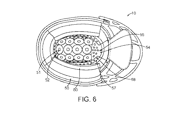
In FIG. 6 is a bottom view of the helmet 10 with components removed to expose
the IIAS 50. Towards the top of the helmet 10, the IIAS 50 is comprised of
cylindrical
impact absorbing components 51 (hereinafter "foam cylinders"). While the
components
of the IIAS 50 are referred to as foam, they may be comprised of any material
with
adequate impact absorbing properties and/or contouring properties. Other
materials that
may be appropriate for use in the IIAS 50 include, but are not limited to,
bladders
containing a fluid (including gas, liquid, semifluid, semisolid), vinyl
encased impact
absorbing members or mechanical shock absorbing apparatuses.
In one embodiment, the foam cylinders 51 are further comprised of a
cylindrical
.. hole 52 oriented along the same axis as the foam cylinder 51. The
cylindrical hole 52 is
preferably oriented along the same axis of the foam cylinder 51, but there are
situations
where it may be preferable to offset the axes. Offsetting the axes would
change the
compressive properties of the foam cylinders 51 without having to change their
material,
diameter or height. The cylindrical holes 52 may be configured as through
holes that
extend from one end of the foam cylinder 51 to the other. The cylindrical
holes 52 may
also be configured as countersunk holes where their depth is less than the
height of the
foam cylinder 51. The cylindrical holes 52 may also be countersunk from either
direction. In some embodiments, the foam cylinders 51 have more than one
cylindrical
- 8 -
CA 03052260 2019-07-31
WO 2018/144420 PCT/US2018/015852
hole 52 to reduce the weight of the foam cylinder and to change its impact
absorption
properties. In some embodiments, the foam cylinders 51 have a centrally
located
cylindrical hole 52 and a plurality of smaller holes located in the radial
direction from the
centrally located cylindrical hole. While the hole has been described as
cylindrical for
.. ease of manufacture, holes or voids of other shapes could be substituted.
In some
embodiments, the cylindrical hole 52 does not extend to either end of the foam
cylinders
51 and, instead, is an internal void.
In the area of the helmet 10 that contacts a player's forehead is a forehead
pad 54
comprised of an impact absorbing material with one or more holes 55. The
forehead pad
54 is shaped to sit against the inside of the rigid core 40 and between the
foam cylinders
51 and elongate strips 57. The elongate strips 57 are comprised of an impact
absorbing
material with one or more holes 58. The area below a player's ears and between
the rigid
core 40 and the player's head are further comprised of ear strips 60 that are
comprised of
an impact absorbing material, optionally comprised of one or more holes 61.
Similar to
the cylindrical holes 52 in the foam cylinders 51, the holes 55, 58 and 61 may
be
configured as through holes, countersunk from either direction or merely voids
internal to
the forehead pad 54.
In FIG. 7 is an exploded perspective view of the helmet 10 with components of
the IIAS 50 removed for clarity. The helmet 10 is optionally further comprised
of a liner
.. 70 removably fixed to the inner surface. The removable liner 70 can be
comprised of a
material that provides a wicking effect, anti-bacterial or anti-microbial
effect or a
moisture barrier effect, among others. Each individual impact absorbing
component in
the IIAS 50 has an air impermeable layer fixed to the end furthest from the
rigid core 40.
- 9 -
CA 03052260 2019-07-31
WO 2018/144420 PCT/US2018/015852
For example, the foam cylinders 51 are fixed to the rigid core 40 on one end
and a
circular air impermeable layer 53 is fixed to the distal end. Similarly, the
forehead pad
54, elongate strips 57 and ear strips 60 are fixed to the rigid core 40 on one
end and an air
impermeable layer 56, 59 and 62 is fixed to their respective distal end.
In one embodiment, the air impermeable layers 53, 56, 59 & 62 (hereinafter
collectively "barrier" 63) are comprised of vinyl and fixed to the underlying
portion of
the IIAS 50 with an adhesive. In another embodiment, the barrier 63 is
comprised of a
plastic sheet adhered to the impact absorbing material. In another embodiment,
the
barrier 63 is a unitary article fixed to each foam section of the underlying
IIAS 50. In
.. another embodiment, the barrier 63 is not air impermeable, but rather is
partially air
permeable, allowing an amount of air to pass through the barrier 63.
The barrier 63 greatly increases the effectiveness of the IIAS 50 by utilizing
the
air trapped in the holes 52, 55, 58 & 61 to absorb impact energy. In one
embodiment, the
impact absorbing members 51, 54, 57 & 60 of the IIAS 50 are comprised of an
open cell
foam and the barrier 63 is comprised of an air impermeable material. When the
impact
absorbing members 51, 54, 57 & 60 are comprised of an open cell foam, the air
contained
in the holes 52, 55, 58 & 61 can only enter or exit the hole through the open
cell structure
of the foam, providing an impact absorbing benefit. The impact absorbing
members 51,
54, 57 & 60 effectively become shock absorbers, where the air flow is
regulated by the
properties of the open cell foam. While particular shapes are disclosed herein
for the
impact absorbing members 51, 54, 57 & 60, many other shapes could easily be
substituted.
- 10 -
CA 03052260 2019-07-31
WO 2018/144420 PCT/US2018/015852
In one embodiment, the impact absorbing members 51, 54, 57 & 60 are comprised
of an open cell foam and the barrier 63 is comprised of a partially air
permeable layer.
When the barrier 63 is comprised of a partially or semi-permeable material
with respect
to air, the shock absorbing effect of the IIAS 50 is reduced. When the barrier
63 is
partially permeable, the air contained in the holes 52, 55, 58 & 61 can exit
through the
open cell structure of the foam or the permeable structure of the barrier 63,
allowing the
air to escape at a greater rate.
The shock absorbing effect of the IIAS 50 may also be modified by changing the
materials used in the IIAS 50 and the relationship between the size of holes
52, 55, 58 &
61 relative to their respective impact absorbing members 51, 54, 57 & 60. For
example,
increasing the diameter of the holes 52, 55, 58 & 61 relative to the size of
their respective
impact absorbing member 51, 54, 57 & 60 reduces the lateral distance that the
air
contained in the holes 52, 55, 58 & 61 must travel through the impact
absorbing member
51, 54, 57 & 60 before escaping. By reducing the lateral distance, the air
contained in the
holes 52, 55, 58 & 61 can escape more easily, therefore reducing the impact
absorbing
capacity of the IIAS 50.
The shock absorbing effect of the IIAS 50 may also be modified by changing the
lateral width of the impact absorbing members 51, 54, 57 & 60 relative to the
diameter of
the holes 52, 55, 58 & 61, changing the property of the materials used in the
IIAS 50 and
changing the thickness of the materials used in the IIAS 50. The shock
absorbing effect
of the IIAS 50 may also be changed in other ways that are known in the art.
In FIG. 8a is a side sectioned view of a portion of the helmet 10, showing the
layering of materials that comprise the EIAS, rigid core 40 and the IIAS. The
view in
-11-
CA 03052260 2019-07-31
WO 2018/144420 PCT/US2018/015852
FIG. 8a is not necessarily to scale and is provided to show the positional
relationship
between the layers of materials. In the preferred embodiment disclosed herein,
the EIAS
is comprised of two layers and the IIAS is comprised of four layers, however,
the number
of layers, the thickness of the layers or the material used in the layers can
be changed or
optimized within the inventive concept expressed herein.
In the preferred embodiment, the IIAS 50 is comprised of one or more layers of
viscoelastic polyurethane foam ("viscoelastic foam"). This material is also
known as
low-resilience polyurethane foam, memory foam or temper foam, along with other
names. Viscoelastic foam is pressure and temperature sensitive and quickly
molds to the
contour of an object pressed against it. Viscoelastic foam's ability to mold
around the
contour of an object makes it an ideal material for the interior of a helmet.
It's use inside
a helmet allows the same helmet to contour to multiple players and eliminate
gaps
between the IIAS 50 and a player's head without resorting to an expensive
helmet
customization process.
Viscoelastic foam also provides effective impact cushioning and temperature
control. Viscoelastic foam is excellent at absorbing impact and when used in
the IIAS 50
and provides impact absorption between a player's head and the rigid core 40.
Viscoelastic foam also stabilizes the temperature of objects placed against
it. It tends to
absorb and release heat slowly, allowing the material to stabilize the
temperature of a
player's skin.
In the preferred embodiment, the IIAS 50 is comprised of three layers of foam,
each with different properties, fixed on one end to the inside of the rigid
core 40 and
sealed on its distal end by the barrier 63. In this embodiment, a first layer
of foam 64 is
- 12 -
CA 03052260 2019-07-31
WO 2018/144420 PCT/US2018/015852
fixed to the inner surface of the rigid core 40. Fixed to the first layer is a
second layer of
foam 65 and fixed to the second layer of foam 65 is a third layer of foam 66.
In some embodiments, the first layer of foam 64 is a soft to medium
lightweight
viscoelastic foam and the second layer of foam 65 is a firm lightweight
viscoelastic foam.
The terms soft, medium and firm refer to the relative difficulty to compress
an area of
foam, otherwise known as the firmness of the foam. A lightweight viscoelastic
foam is
capable of absorbing the energy of sudden impacts. A material that is
particularly well
suited for this purpose is an elastomeric, polyurethane viscoelastic open cell
foam with a
density between one quarter and 15 pounds per cubic foot. In this embodiment,
the first
layer 64 is comprised of a medium-soft lightweight viscoelastic foam with a
density of
one half to one pound per cubic foot and the second layer 65 is comprised of a
firm
lightweight viscoelastic foam with a density of one to one and a half pounds
per cubic
foot.
In this embodiment, the third layer of foam 66 fixed to the second layer of
foam
.. 65 is a viscoelastic foam with gel-like properties, an open cell structure
and a soft dough-
like consistency (hereinafter "gel-like foam"). Gel-like foam with a density
between 15
and 50 pounds per cubic foot is particularly effective at maintaining its
shape when worn
by a user and providing effective impact cushioning. In some embodiments, a
gel-like
foam with a density between 15 and 33 pounds per cubic foot is used to provide
effective
impact cushioning in the helmet. In another embodiment, a gel-like foam with a
density
between 30 and 35 pounds per cubic foot is used in the first layer 64. An
important
characteristic of the gel-like foam used in this embodiment is that it is
capable of easily
molding around a player's head to eliminate gaps.
- 13 -
CA 03052260 2019-07-31
WO 2018/144420 PCT/US2018/015852
In the preferred embodiment, it is preferable that the first layer 664 and
second
layer 65 are substantially the same thickness and that the third layer 66 is
50-70% of the
thickness of either the first or second layer 64 & 65. In this instance,
substantially the
same thickness means a thickness up to and including a 10% variation from one
another,
so that if the second layer is 1.0 inch thick, the third layer 66 would still
be substantially
the same with a thickness of 1.1 inches. While the use of viscoelastic foam
has been
disclosed as the preferred embodiment, it is appreciated that other materials
with similar
impact absorbing and density properties would also be suitable for this
application.
In some embodiments, the first layer 64 comprises a medium lightweight
viscoelastic foam with a thickness of about 0.3 to 0.75 inches, the second
layer 65
comprises a medium soft lightweight viscoelastic foam with a thickness of
about 0.30 to
0.75 inches and the third layer 66 comprises a gel-like foam with a thickness
of about
0.20 to 0.50 inches and a density of about 15 pounds per cubic foot to 50
pounds per
cubic foot. In some embodiments, the first layer 64 comprises a medium
lightweight
viscoelastic foam with a thickness of about 0.4 to 0.6 inches, the second
layer 65
comprises a medium soft lightweight viscoelastic foam with a thickness of
about 0.4 to
0.6 inches and the third layer 66 comprises a gel-like foam with a thickness
of about 0.25
to 0.35 inches and a density of about 15 pounds per cubic foot to 50 pounds
per cubic
foot. In some embodiments, the first layer 64 comprises a medium lightweight
viscoelastic foam with a thickness of about 0.45 inches to 0.55 inches, the
second layer
65 comprises a medium soft lightweight viscoelastic foam with a thickness of
about 0.45
to 0.55 inches and the third layer 66 comprises a gel-like foam with a
thickness of about
0.25 to 0.32 inches and a density of about 15 pounds per cubic foot to 50
pounds per
- 14 -
CA 03052260 2019-07-31
WO 2018/144420 PCT/US2018/015852
cubic foot. In some embodiments, the first layer 64 comprises a firm
lightweight
viscoelastic foam with a thickness of about 0.4 inches to 1.0 inch the second
layer 65
comprises a medium lightweight viscoelastic foam with a thickness of about 0.3
to 0.75
inches and the third layer 66 comprises a gel-like foam with a thickness of
about 0.2 to
0.5 inches and a density of about 15 pounds per cubic foot to 50 pounds per
cubic foot.
In some embodiments, the first layer 64 comprises a firm lightweight
viscoelastic foam
with a thickness of about 0.6 inches to 0.9 inches the second layer 65
comprises a
medium lightweight viscoelastic foam with a thickness of about 0.4 to 0.6
inches and the
third layer 66 comprises a gel-like foam with a thickness of about 0.25 to
0.35 inches and
a density of about 15 pounds per cubic foot to 50 pounds per cubic foot. In
some
embodiments, the first layer 64 comprises a firm lightweight viscoelastic foam
with a
thickness of about 0.7 inches to 0.8 inches the second layer 65 comprises a
medium
lightweight viscoelastic foam with a thickness of about 0.45 to 0.55 inches
and the third
layer 66 comprises a gel-like foam with a thickness of about 0.25 to 0.32
inches and a
density of about 15 pounds per cubic foot to 50 pounds per cubic foot.
In the preferred embodiment, the EIAS 30 is comprised of a layer 31 of
lightweight viscoelastic foam fixed to the exterior of the rigid core 40 to
absorb the
impact energy from sudden impacts on the exterior of the helmet 10. In one
embodiment,
the layer 31 is comprised of an elastomeric, polyurethane viscoelastic open
cell foam
with a density between one half and 15 pounds per cubic foot. In another
embodiment,
the layer 31 is comprised of an elastomeric, polyurethane viscoelastic open
cell foam
with a density between one half and eight pounds per cubic foot. In another
embodiment,
the layer 31 is comprised of an elastomeric, polyurethane viscoelastic open
cell foam
- 15 -
CA 03052260 2019-07-31
WO 2018/144420 PCT/US2018/015852
with a density between one and two pounds per cubic foot. In another
embodiment, the
layer 31 is comprised of an elastomeric, polyurethane viscoelastic open cell
foam with a
density between one and one and a half pounds per cubic foot. While a
viscoelastic foam
is used in this embodiment, other materials capable of absorbing high impact
energy
would also be suitable.
The EIAS 30 is further comprised of a water-resistant layer 32 fixed to the
top of
the layer 31. Various waterproof layers or coatings would be suitable,
including, but not
limited to, a rubberized coating or room temperature vulcanization silicone.
In some
embodiments, a two part, flexible polyurethane adhesive is applied as the
water-resistant
layer 32. The two part, flexible polyurethane adhesive must be hard enough to
resist
scuffing and tearing, but also soft enough to remain flexible. Materials with
a Shore
hardness of A30 to A90 can be appropriate for use in the water-resistant layer
32. In
some embodiments, the water-resistant layer 32 is comprised of a two part,
flexible
polyurethane adhesive with a Shore hardness between A40 and A70. In other
embodiments, the water-resistant layer 32 is comprised of a two part, flexible
polyurethane adhesive with a Shore hardness of approximately A50. In one
embodiment,
the layer 31 is three to six times as thick as the water-resistant layer 32.
In another
embodiment, the layer 31 is four to five times as thick as the water-resistant
layer 32. In
another embodiment, the water-resistant layer 32 is approximately 1.0 mm
thick. To
increase the abrasion resistance of the EIAS 30, the outer surface may
optionally be
wrapped with a flexible abrasion resistant material, such as a fiber
reinforced cloth.
Various reinforced materials would be suitable, including, but not limited to,
Exotex
Dacron cloth.
- 16 -
CA 03052260 2019-07-31
WO 2018/144420 PCT/US2018/015852
In some embodiments, the EIAS 30 comprises a single layer of ethylene-vinyl
acetate (hereinafter "EVA"). When the EIAS 30 comprises EVA, the material may
be
applied in sheet form at thicknesses of between and including 0.1 inches to
0.8 inches.
When the EIAS 30 comprises EVA, it is preferable for the material to have a
thickness of
.. between and including 0.2 inches to 0.3 inches.
In the preferred embodiment, the rigid core 40 is a fiber reinforced polymer
comprised of carbon fibers, aramid fibers and a resin. In one embodiment, the
rigid core
40 is comprised of a layer of carbon fiber reinforced polymer on the exterior
and a layer
of Kevlar reinforced polymer (hereinafter "Kevlar") on the interior of the
rigid core 40,
where the layer of Kevlar is approximately three times the thickness of the
layer of
carbon fiber. This thickness ratio of Kevlar to carbon fiber provides an
effective balance
between strength, weight and durability against impact. In another embodiment,
the layer
of Kevlar on the interior of the rigid core 40 is about two times the
thickness of the layer
of carbon fiber on the exterior of the rigid core 40. A rigid core 40
comprised only of
carbon fiber is possible, but rigid core 40 would need to be comparatively
thick to be
capable of sustaining repetitive impacts normal to the direction of the carbon
fiber
filaments. The Kevlar layer provides additional strength to the carbon fiber
and is more
flexible to impacts normal to the direction of the Kevlar fibers, making the
rigid core 40
more resistant to cracking. In another embodiment, the rigid core 40 is
comprised of a
.. Kevlar layer and carbon fiber layer where the Kevlar layer is one to five
times the
thickness of the carbon fiber layer. In another embodiment, the rigid core 40
is
comprised of a Kevlar layer and carbon fiber layer where the Kevlar layer is
approximately 0.6 mm thick and the carbon fiber layer is approximately 0.2 mm
thick. In
- 17 -
CA 03052260 2019-07-31
WO 2018/144420
PCT/US2018/015852
some embodiments, the carbon fiber layer is located on the interior of the
rigid core 40
and the Kevlar layer is located on the exterior of the rigid core 40.
In one embodiment, the rigid core 40 is modified with a rubberizing compound
to
increase the flexibility of the rigid core 40 in impacts that are normal to
the axial
direction of the carbon fiber filaments. Many types of rubberizing compounds
and
flexibility promoters are known in the art and could be used in the
construction of the
rigid core 40. In another embodiment, the resin used to bond the carbon fiber
filaments
and the Kevlar fibers of the rigid core 40 is comprised of 30-50% epoxy
laminating resin
and 50-70% rubberizing compound. In another embodiment, the resin used to bond
the
carbon fiber filaments and Kevlar fibers of the rigid core 40 is comprised of
40% epoxy
laminating resin and 60% rubberizing compound. In another embodiment, the
resin used
to bond the carbon fiber filaments and Kevlar fibers of the rigid core 40 is
comprised of
35% epoxy laminating resin and 65% rubberizing compound. In another
embodiment,
the resin used to bond the carbon fiber filaments and Kevlar fibers of the
rigid core 40
has a hardness of approximately 6.50 on a 0 to 10 scale.
In some embodiments, the carbon fiber and Kevlar fibers are oriented to
maximize the rigid core's 40 resistance to frontal and rear impacts. The
carbon fiber and
Kevlar cloth can be oriented so that the fibers towards the front and rear of
the helmet are
positioned horizontally and vertically in a woven pattern.
While carbon fiber and Kevlar are well suited for use as the rigid core 40, it
is
appreciated that there are multiple materials that would be suitable. For
instance,
Exotex Dacron has a high strength to weight ratio that exceeds that of carbon
fiber and
would also be an ideal material for the rigid core 40 when combined with a
plastic resin.
- 18 -
CA 03052260 2019-07-31
WO 2018/144420 PCT/US2018/015852
Other type of basalt fiber based composite materials would have similar high
strength and
low weight characteristics. The purpose of the rigid core 40 is to provide
structure to the
helmet 10 and many materials could be suitable based on the desired weight,
crush
resistance and cost of the helmet.
In FIG. 8b is a side sectioned view of a portion of an alternative embodiment
of
the helmet 100, showing the layering of materials that comprise the EIAS,
rigid core 140
and the IIAS. The view in FIG. 8b is not necessarily to scale and is provided
to show the
positional relationship between the layers of materials. In the alternative
embodiment
disclosed herein, the EIAS is comprised of two layers and the IIAS is
comprised of four
layers, however, the number of layers, the thickness of the layers or the
material used in
the layers can be changed or optimized within the inventive concept expressed
herein.
In the alternative embodiment, the IIAS is comprised of three layers of foam,
each
with different properties, fixed on one end to the inside of the rigid core
140 and sealed
on its distal end by the barrier 163. In the alternative embodiment, the first
layer 164
fixed to the inside of the rigid core 140 is a soft to medium firmness
lightweight
viscoelastic foam is fixed to the inside of the rigid core 140. A layer of
firm hardness
lightweight viscoelastic foam, comprising the second layer 165, is fixed to
the bottom of
the soft to medium firmness foam. In this embodiment, the first layer 164 is
comprised
of a medium-soft lightweight viscoelastic foam with a density of one half to
one pound
per cubic foot and the second layer 165 is comprised of a firm lightweight
viscoelastic
foam with a density of one to one and a half pounds per cubic foot. In some
embodiments, the first layer 164 is comprised of a lightweight viscoelastic
foam with a
- 19 -
CA 03052260 2019-07-31
WO 2018/144420 PCT/US2018/015852
density of one quarter to six pounds per cubic foot and the second layer 165
is comprised
of a lightweight viscoelastic foam with a density of one half to six pounds
per cubic foot.
In the alternative embodiment, the third layer 166 is comprised of a gel-like
foam
with a density between 30 and 35 pounds per cubic foot. In some embodiments,
the third
layer 166 is comprised of a gel-like foam with a density between 15 and 50
pounds per
cubic foot.
In the alternative embodiment, it is preferable that the first layer 164 and
third
layer 166 are substantially the same thickness and that the second layer 165
is 125-175%
of the thickness of either the first or third layer 164 & 166. In this
instance, substantially
the same thickness means a thickness up to and including a 10% variation from
one
another, so that if the second layer is 1.0 inch thick, the third layer 166
would still be
substantially the same with a thickness of 1.1 inches. In some embodiments,
the first
layer 164 is approximately a half inch thick, the second layer 165 is
approximately three
quarters of an inch thick and the third layer is approximately a half inch
thick. In some
embodiments, it is preferable for the first layer 164 to be about 1.5 times
the thickness of
the second layer 165 and for the third layer to be about 0.6 times the
thickness of the
second layer 165. In some embodiments, it is preferable for the first layer
164 to be
about the same thickness as the second layer 165 and for the third layer to be
about 0.6
times the thickness of the second layer 165.
In the alternative embodiment, the EIAS is comprised of a layer 131 of
lightweight viscoelastic foam fixed to the exterior of the rigid core 140 to
absorb the
impact energy from sudden impacts on the exterior of the helmet 100. In one
embodiment, the layer 131 is comprised of an elastomeric, polyurethane
viscoelastic
-20-
CA 03052260 2019-07-31
WO 2018/144420 PCT/US2018/015852
open cell foam with a density between one half and 15 pounds per cubic foot.
In another
embodiment, the layer 131 is comprised of an elastomeric, polyurethane
viscoelastic
open cell foam with a density between one half and eight pounds per cubic
foot. In
another embodiment, the layer 131 is comprised of an elastomeric, polyurethane
viscoelastic open cell foam with a density between one and two pounds per
cubic foot. In
another embodiment, the layer 131 is comprised of an elastomeric, polyurethane
viscoelastic open cell foam with a density between one and one and a half
pounds per
cubic foot. While a viscoelastic foam is used in this embodiment, other
materials capable
of absorbing high impact energy would also be suitable. The EIAS of the
alternative
embodiment is further comprised of a water-resistant layer 132 fixed to the
top of the
layerl 31. Various waterproof layers or coatings would be suitable, including,
but not
limited to, the materials disclosed for the water-resistant layer 32 of the
preferred
embodiment. The rigid core 140 of the alternative embodiment may be comprised
of
multiple suitable materials, including, but not limited to, the materials
disclosed for the
rigid core 40 of the preferred embodiment.
In FIGS. 9-11 are exploded perspective views of the inside of the helmet with
components of the IIAS 50 removed for clarity. These figures show the sizing
and
position of each type of foam used in the preferred embodiment. Foam cylinders
51 are
used to protect the top of a player's head to balance the weight of the IIAS
50 and its
impact absorption qualities. The foam cylinders 51 are designed with an air
void volume
(contained in the cylindrical holes 52) to foam volume ratio that optimizes
the impact
absorption and weight of the IIAS 50.
-21-
CA 03052260 2019-07-31
WO 2018/144420 PCT/US2018/015852
The top of the helmet experiences high impact hits as well as many lower
energy
hits. Therefore, the top of the helmet must be soft enough to protect a player
from lower
energy subconcussive impacts and remain capable of protecting a player from
high
energy impacts. The IIAS 50 and the foam cylinders 51, in particular, are
designed to
deflect when subject to subconcussive impacts and absorb high energy impacts
without
bottoming out. Bottoming out in this application is when a material has been
compressed
to its minimum height. Bottoming out is undesirable in a helmet because once
the impact
absorbing material bottoms out, it cannot provide any substantial impact
absorption.
The foam cylinders 51 are effective at providing absorption of subconcussive
and
high energy impacts because of the sealed air void located at their centers.
An open cell
foam can be readily compressed, however air in a sealed space is much more
difficult to
compress. The air in the center of the foam cylinders 51 is not completely
sealed, in that
it can escape through the open cell structure of the foam, but when subject to
a high
energy impact, the air momentarily acts similarly to air trapped in a sealed
container to
absorb the high energy impact. As the foam cylinder compresses, the air is
pushed
through the open cell structure of the foam, absorbing the remainder of the
impact. The
use of air in a void at the center of the foam cylinders 51 allows the use of
a softer foam
than would otherwise be appropriate because it reduces the risk of bottoming
out in high
energy impacts.
The forehead pad 54, elongate pieces 57 and ear pieces 60 use a smaller air
void
to foam ratio because they are subject to more high impact hits than the top
of the helmet.
The use of smaller air voids provides a level of protection from bottoming out
while also
providing shock absorption from the foam itself
- 22 -
CA 03052260 2019-07-31
WO 2018/144420 PCT/US2018/015852
In FIGS. 12-16 are detailed views of three types of foam components used in
the
IIAS 50. In FIGS. 12-13 is an example of a foam cylinder 51 with the vinyl
barrier 53
removed. In FIGS. 14 & 15 is an example of a forehead pad 54 with the vinyl
barrier 56
removed. In FIG. 16 is an example of an elongate pad 57 with the vinyl barrier
59
removed.
What has been described is a football helmet designed to reduce the occurrence
of
concussions and the magnitude of subconcussive impacts to the head. While this
disclosure shows the invention as a football helmet, all or part of the
invention is capable
of being used in other applications. In this disclosure, there is shown and
described only
the preferred embodiments of the invention, but, as aforementioned, it is to
be understood
that the invention is capable of use in various other combinations and
environments and
is capable of changes or modifications within the scope of the inventive
concept as
expressed herein.
-23-