Note : Les descriptions sont présentées dans la langue officielle dans laquelle elles ont été soumises.
- 1 -
Body-wearable medical device
Description
The invention relates to a body-wearable medical device, such as an analyte
monitoring
system or a patch-mounted pump.
Such systems are available for monitoring of certain analytes or agents,
specifically
glucose or lactate in body fluids like blood or interstitial fluid by readings
of an implanted
sensor, specifically an electrochemical sensor. The subcutaneously implanted
sensor
remains in the interstitial tissue over an extended period of time even up to
several weeks.
Then, the in vivo detected measurement signals may be indicative of an
analyte, e.g.
glucose in the blood of the subject. The monitoring may be a nearly real-time
continuous
or quasi continuous or periodic approach for frequently providing/updating
analyte values
without sample handling or similar user interaction.
In present practice, continuous glucose monitoring (CGM)-systems include a so-
called
bodymount as a patch which comprises a rigid housing portion or stiff mounting
platform
on which the electronics unit is mounted galvanically coupled the sensor. As
the human
body is relatively soft and flexible, the rigid housing or platform in
connection with the
sensor cannot follow the deflections and elongations, thereby resulting
shearing forces
which lead to early detachment of the bodymount from the skin. Furthermore,
the platform
on the body has only reduced breathability, such that humidity accumulates
therebelow,
which also undesirably reduces the possible wearing time. As a further
problem, the user
may need a remote control for actuating the device.
WO 2016/187536 Al describes an ultra-thin wearable sensing device which
includes a
sensor tag IC that enables the device to communicate wirelessly to a reading
device. The
wearable sensing device includes one or more sensors connected to the sensor
tag IC that
Date Recue/Date Received 2021-01-11
CA 03053362 2019-08-12
WO 2018/185138 PCT/EP2018/058566
- 2 -
sense characteristics of the person, animal or object that the sensing device
comes in
contact with. The sensed characteristics can include biological signals (e.g.,
ECG, EMG,
and EEG), temperature, galvanic skin response (GSR), heat flux and chemicals
or fluids
released by the skin. The reading device can display the information to the
user and/or
transmit the sensor data to a remote location for further processing. A doctor
can review
the data or have the data further analyzed and use this data or information to
assist with
treatment.
WO 2016/090189 Al describes a non-invasive epidermal electrochemical sensor
device
which includes an adhesive membrane; a flexible or stretchable substrate
disposed over the
adhesive membrane; and an anodic electrode assembly disposed over the flexible
or
stretchable substrate including an iontophoretic electrode. The device
includes a cathodic
electrode assembly disposed adjacent to the anodic electrode assembly over the
flexible or
stretchable substrate and includes an iontophoretic electrode. Either the
cathodic electrode
1 5 assembly or the anodic electrode assembly also includes a sensing
electrode that includes a
working electrode and at least one of a counter electrode or a reference
electrode. The
iontophoretic electrode in either the anodic electrode assembly or the
cathodic electrode
assembly that includes the sensing electrode is disposed on the substrate to
at least partially
encompass the working electrode and the at least one of the counter electrode
or the
2 0 reference electrode. The device includes an electrode interface
assembly including inde-
pendent electrically conductive contacts.
US 2008/161656 Al describes a device, system, and method for delivering a
device such
as a sensor or fluid transport structure or a fluid transport structure sensor
combination
25 into, for example, mammalian skin and receiving, analyzing, and
displaying signals from
the device such as a sensor. A system includes a reusable sensor assembly
including a
transmitter, microcontroller, and housing plus disposable sensor assembly
including a
housing having an opening for receiving both the distal end of a biosensor, a
sensor
insertion guidance structure, and a transmission apparatus for transmitting
signals received
30 from the sensor to a reusable sensor assembly for transmission to an
external electronic
monitoring unit.
CA 03053362 2019-08-12
WO 2018/185138 PCT/EP2018/058566
- 3 -
US 2014/276167 Al describes a wearable patch and method for automatically
monitoring,
screening, and/or reporting events related to one or more health conditions
(e.g., sleeping
or breathing disorders, physical activity, arrhythmias) of a subject.
WO 2013/136181 A2 describes a pump assembly mounted to or supported by a
dressing
for reduced pressure wound therapy. The dressing can have visual pressure,
saturation,
and/or temperature sensors to provide a visual indication of the level of
pressure,
saturation, and/or temperature within the dressing. Additionally, the pump
assembly can
have a pressure sensor in communication with the flow pathway through the
pump, and at
least one switch or button supported by the housing, the at least one switch
or button being
accessible to a user and being in communication with the controller. The pump
assembly
can have a controller supported within or by the housing, the controller being
configured to
control an operation of the pump. The pump can be configured to be sterilized
following
the assembly of the pump such that all of the components of the pump have been
sterilized.
WO 2017/003857 Al describes a flexible, body-mountable analyte sensing device
which
includes a flexible substrate configured for mounting to skin of a living
body. The sensing
device additionally includes a sensor probe attached to the flexible substrate
and
configured to penetrate the skin such that a sensor disposed on the end of the
sensor probe
can be exposed to an analyte in interstitial fluid. The sensor could be an
electrochemical
sensor that includes two or more electrodes disposed at the end of the sensor
probe and
configured to electrochemically detect the analyte. The sensing device is
configured to
display detected concentrations or other information about the analyte in the
interstitial
fluid. The flexible substrate of the sensing device is configured to be
adhered or otherwise
.. mounted to the skin in a manner that minimally impacts activities of the
living body.
US 2016/310049 Al describes techniques for measuring ion related metrics at a
user's skin
surface are disclosed. In one aspect, a method for operating a wearable device
may involve
determining, based on output of one or more ion selective field effect
transistor sensors,
various physiological conditions such as a state of hydration, a state of skin
health, or the
cleanliness of the wearable device or an associated garment.
- 4 -
On this basis, the object of the invention is to further improve the known
systems and to
provide a design which allows for long-term wear capability and improved user
convenience.
The invention is based on the idea of providing a comfortable self-adhering
flexible
1 0 electronics patch with integrated electronic interfaces or actuators.
As used herein the term
"patch" refers to at least one arbitrary shaped fastening element which is
configured to be
attached directly to the skin of the user, i.e. without using additional or
further fastening
elements. As used herein, the term "self-adhering" refers to the patch
comprising at least
one attachment side, for example a bottom side, adapted to attach and/or mount
the patch
to the skin, wherein the attachment side comprises at least one adhesive
and/or is coated
with at least one adhesive coating. As used herein, the term "electronics
patch" refers to a
patch which comprises at least one electronic element As used herein, the term
"flexible
electronics patch" refers to the fact that the electronics patch has flexible
properties such
that the electronics patch is bendable and/or stretchable to follow the
contour of the skin.
The patch may have a stretchability of at least 20 % in at least two
directions, preferably in
all directions. As used herein "stretchability of at least 20 %" refers to
that a patch having a
length of, for example, 10 cm (centimeters) can be stretched to a length of at
least 12 cm
(centimeters). Accordingly, it is proposed that the electronics patch includes
a flexible
printed circuitry or circuits which are applied directly on a foil substrate,
and that a user
interface is integrated with the patch for allowing the user to directly
control the device. As
used herein, the term "the electronics patch includes a flexible printed
circuitry or circuits"
refers to that at least one flexible printed circuitry is part of the patch
and/or is integrated
within or into the patch, in particular is integrated within at least one
substrate of the patch
and/or on at least one substrate of the patch and/or is integrated within at
least one layer of
the patch, and/or that the flexible printed circuitry is embedded within the
patch and/or that
the flexible printed circuitry is incorporated in the patch. The patch
comprises the foil
substrate having the flexible printed circuitry printed thereon. Specifically,
the at least one
Date Recue/Date Received 2021-01-11
CA 03053362 2019-08-12
WO 2018/185138 PCT/EP2018/058566
- 5 -
flexible printed circuitry may be integrated and/or incorporated and/or
embedded in the
patch such that the patch itself is arranged and/or configured as electronic
unit. Thus, the at
least one flexible printed circuitry may be comprised by the patch itself,
without the need
of an additional and/or separate element adapted to store or house the
flexible printed
circuitry such as a housing or base unit or something similar. Thus, the
flexible patch
avoids the disadvantages of a rigid platform and is bendable and/or
stretchable to follow
the contour of the skin. At the same time, the integrated interface allows for
user
interaction without the need to provide actuators into a stiff housing.
Thereby the overall
operating cycle can be prolonged and the user convenience can be significantly
improved.
In this context, a further improvement provides that the user interface is an
integrated part
of the self-adhering flexible electronics patch. It is further preferred that
the user interface
is directly applied to the foil substrate. As used herein, the term "the user
interface is
integrated part of the self-adhering flexible electronics patch" refers to
that the user
interface is part of the patch and/or is comprised within or into the patch,
in particular is
integrated within at least one substrate of the patch and/or on at least one
substrate of the
patch and/or is integrated within at least one layer of the patch, and/or that
the user
interface is embedded within the patch and/or that the user interface is
incorporated in the
patch. For example, the patch may comprise the foil substrate having the user
interface
printed thereon. Thus, the user interface may be comprised by the patch
itself, without the
need of an additional and/or separate element adapted to store or house the
user interface
such as a housing or base unit or something similar.
In an advantageous configuration, the user interface comprises at least one
switch, wherein
the switch is configured to operate a component on the electronics patch, such
that a direct
user interaction is possible without remote control.
For further improved integration, the switch comprises printed conducting
elements
applied on the foil substrate.
Preferably, the switch is one of manually operable by the user or
automatically operable in
dependence of a predefined switching condition
CA 03053362 2019-08-12
WO 2018/185138 PCT/EP2018/058566
- 6 -
In this connection, it is also advantageous to use the switch for at least one
function of the
group comprising power-on/off, delivering bolus doses, emergency shutdown.
Advantageously, the switch can be configured to power a display component of
the system
on or off.
In combination with a separate pump system, the switch can be configured to
interact with
the functionalities of the pump system. For instance, the switch may be used
as a bolus
button for delivering a bolus. In such an embodiment, the sensor data
indicative of a
glucose level may be used to determine a corresponding bolus and the
determined bolus
may be released by the pump when the switch is pressed for example by
communicating a
corresponding signal to the pump.
.. Additionally or alternatively the switch may be configured to provide for
an emergency
shutdown of a pump Such a situation can arise when the sensor indicates a
glucose level
that tends to hypoglycemia, a situation in which the basal insulin delivery
needs immediate
suspension.
Specifically in connection with a patch pump, which is worn on the body, a
flexible switch
provided on a flexible printed circuitry is advantageous for manual triggering
of bolus
doses of insulin. This allows a small-sized implementation for direct user
interaction.
In a further advantageous embodiment, the user interface comprises a display
component
operable for displaying information related to the operation of the device, in
particular
information related to at least one of device status, measuring results, user
guidance,
warnings. Thus, a user information or interaction is possible without external
devices in
rigid housing.
In a simplified embodiment, the user interface comprises at least one single
LED or an
array of LEDs as a display component operable for displaying information
related to the
use of the device.
CA 03053362 2019-08-12
WO 2018/185138 PCT/EP2018/058566
- 7 -
A more sophisticated approach provides that the display component is formed as
a flexible
screen, in particular a flexible OLED screen, and the screen is embedded on
the foil
substrate or is mounted on the body as a separate flexible patch and
communicates with the
.. self-adhering flexible electronics patch over a distance. In the latter
case, the sensor patch
may be worn on a non-visible body area, whereas the display patch is visibly
attached to
the body. Then, in combination with a user-activated switching arrangement on
the
electronics patch, the device can be operated independently of an external
remote control.
In this connection it is further advantageous when a data connection between
the flexible
printed circuitry and the display component is provided by conductive
textiles. This allows
to have the display always visible on top of the clothing.
In order to easily adapt to a varying skin contour, the foil substrate of the
flexible printed
circuits should have a thickness of less than lmm, preferably 10-250 microns
and
advantageously 50-100 microns, more preferably 60 - 90 microns and most
preferably 70 -
80 microns. Depending on the stability of the foil, a thickness in the range
of 10 to 50
microns might also be feasible.
A further improvement provides that foil substrate is stretchable in at least
one direction by
more of 20% of its initial length. In an embodiment the foil substrate may be
stretchable in
at least two directions by more than 20 %. In an embodiment the foil substrate
is
stretchable in all directions by more than 20 %. As used herein the term "more
than 20 %"
in an embodiment means that a foil substrate having a length of for example 10
cm
(centimeters) can be stretched along its length to at least 12 cm
(centimeters). A
stretchability in the range of 20% is similar to that of the skin and thus
provides an
optimized and long-lasting wear comfort.
The electronics patch may comprise at least one deformable electronics element
and/or at
least one rigid or semi-rigid electronics element. For example, the
electronics patch may
comprise the at least one flexible printed circuitry including at least one
electronic element
selected from the group consisting of: at least one conductive path, at least
one resistor, at
CA 03053362 2019-08-12
WO 2018/185138 PCT/EP2018/058566
- 8 -
least one capacitor, and at least one battery, wherein the electronic elements
may be
deformable components. For example, the electronics patch may comprise rigid
or semi-
rigid components such as one or more of at least one integrated circuit chip,
at least one
processor, at least one storage medium, at least one antenna, and at least one
battery. As
used herein, the term "comprises at least one deformable electronics element
and/or at least
one rigid or semi-rigid electronics element" refers to that the deformable
electronics
element and/or the rigid or semi-rigid electronics element is part of the
patch and/or is
integrated within or into the patch, in particular is integrated within at
least one substrate of
the patch and/or on at least one substrate of the patch and/or is integrated
within at least
one layer of the patch, and/or that the deformable electronics element and/or
the rigid or
semi-rigid electronics element is embedded within the patch and/or that the
deformable
electronics element and/or the rigid or semi-rigid electronics element is
incorporated in the
patch. For example, the patch may comprise the insulating foil substrate
having the
deformable electronics element and/or the rigid or semi-rigid electronics
element printed
thereon, in particular directly. Specifically, the deformable electronics
element and/or the
rigid or semi-rigid electronics element may be integrated and/or incorporated
and/or
embedded in the patch such that the patch itself is arranged and/or configured
as electronic
unit. Thus, the deformable electronics element and/or the rigid or semi-rigid
electronics
element may be comprised by the patch itself, without the need of an
additional and/or
separate element adapted to store or house the deformable electronics element
and/or the
rigid or semi-rigid electronics element such as a housing or base unit or
something similar.
A particular embodiment further comprises that the flexible printed circuitry
includes at
least one of conductive paths, resistors, capacitors and batteries as
deformable components.
Another possibility provides that the flexible electronics patch comprises at
least one of
integrated circuit chips, processors, storage media, antennas and batteries as
rigid or semi-
rigid components which are distributed such that the electronics patch overall
remains
deformable to adapt its shape to a varying contour of the skin during use.
Advantageously, the flexible electronics patch comprises a printed battery
which consists
of functional materials, e.g. a zinc manganese dioxide system, printed on a
flexible
CA 03053362 2019-08-12
WO 2018/185138 PCT/EP2018/058566
- 9 -
substrate. In order to provide a large capacity, the printed battery should
cover a large area
or even the whole patch.
In this context, it is also advantageous when the flexible printed circuitry
comprises an
antenna for a wireless connection to a remote device, and when the antenna is
arranged
such that it is not shielded by the printed battery (which may include a
metallic foil) in a
direction away from the user's body. In specific configurations, multiple
antennas may be
used above and below the printed battery, or on the side thereof.
In a particular useful embodiment, the analyte monitoring system is formed as
a continuous
glucose monitoring system comprising a skin-implantable glucose sensor.
For a closed loop operation, it is also preferable that the patch-mounted pump
is provided
to deliver doses of a medical agent such as insulin to the body of the user.
In a further aspect a method for controlling at least one body-wearable
medical device
according to any one of the embodiments as described above or described in
detail below
is proposed. The method comprises the following steps which, as an example,
may be
performed in the given order. It shall be noted, however, that a different
order is also
.. possible. Further, it is also possible to perform one or more of the method
steps once or
repeatedly. Further, it is possible to perform two or more of the method steps
simultaneously or in a timely overlapping fashion. The method may comprise
further
method steps which are not listed. The method comprises the following steps:
i) adhering a self-adhering flexible electronics patch to the skin of a
user, wherein the
self-adhering flexible electronics patch is deformable to follow the contour
of the skin,
wherein the electronics patch includes a flexible printed circuitry which is
applied directly
on a foil substrate;
ii) controlling the device by the user by using a user interface, wherein
the user
interface is an integrated part of the self-adhering flexible electronics
patch.
CA 03053362 2019-08-12
WO 2018/185138
PCT/EP2018/058566
- 10 -
With respect to embodiments and definition of the method reference is made to
the
description of the body-wearable medical device above and as described in
further detail
below.
.. Summarizing and without excluding further possible embodiments, the
following
embodiments may be envisaged:
Embodiment 1: Body-wearable medical device, such as an analyte monitoring
system or a
patch-mounted pump, comprising a self-adhering flexible electronics patch
which adheres
to the skin of a user and is deformable to follow the contour of the skin,
wherein the
electronics patch includes a flexible printed circuitry which is applied
directly on a foil
substrate, and wherein a user interface is configured for allowing the user to
control the
device.
Embodiment 2: The device according to embodiment 1, wherein the user interface
comprises at least one switch, the switch being configured to operate a
component on the
electronics patch.
Embodiment 3: The device according to embodiment 2, wherein the switch
comprises
.. printed conducting elements applied on the foil substrate.
Embodiment 4: The device according to embodiment 2 or 3, wherein the switch is
one of
manually operable by the user or automatically operable in dependence of a
predefined
switching condition.
Embodiment 5: The device according to any of embodiments 2 to 4, wherein the
switch is
used for at least one of the group comprising power-on/off, delivering bolus
doses,
emergency shutdown.
Embodiment 6: The device according to any of embodiments 1 to 5, wherein the
user
interface comprises a display component operable for displaying information
related to the
CA 03053362 2019-08-12
WO 2018/185138 PCT/EP2018/058566
- 11 -
operation of the device, in particular information related to at least one of
device status,
measuring results, user guidance, warnings.
Embodiment 7: The device of embodiment 6, wherein the user interface comprises
at least
one single LED or an array of LEDs as a display component operable for
displaying
information related to the use of the device.
Embodiment 8: The device of embodiment 6 or 7, wherein the display component
is
formed as a flexible screen, in particular a flexible OLED screen, and the
screen is
.. embedded on the foil substrate or is mounted on the body as a separate
flexible patch
communicating with the self-adhering flexible electronics patch.
Embodiment 9: The device according to any of embodiments 1 to 8, wherein a
data
connection between the flexible printed circuitry and the user interface is
provided by
1 5 conductive textiles.
Embodiment 10: The device according to any of embodiments 1 to 9, wherein the
foil
substrate has a thickness of less than lmm, preferably 10-250 microns, more
preferably 50-
100 microns and most preferably 70-80 microns.
Embodiment 11: The device according to any of embodiments 1 to 10, wherein the
foil
substrate is stretchable in at least one direction by more of 20% of its
initial length.
Embodiment 12: The device according to any of embodiments 1 to 11, wherein the
flexible
.. printed circuitry includes at least one of conductive paths, resistors,
capacitors and batteries
as deformable components.
Embodiment 13: The device according to any of embodiments Ito 12, wherein the
electronics patch comprises a printed battery which consists of functional
material printed
on a flexible substrate.
CA 03053362 2019-08-12
WO 2018/185138
PCT/EP2018/058566
- 12 -
Embodiment 14: The device of embodiment 13,wherein the flexible printed
circuitry
comprises an antenna for a wireless connection to a remote device, and wherein
the
antenna is arranged such that it is not shielded by the printed battery in a
direction away
from the user's body.
Embodiment 15: The device according to any of embodiments 1 to 14, wherein the
analyte
monitoring system is formed as a continuous glucose monitoring system
comprising a
skin-implantable glucose sensor which is at least partially insertable into
the skin or fully
implantable under the skin.
Embodiment 16: A method for controlling at least one body-wearable medical
device
according to any one of the preceding embodiments, wherein the method
comprises the
following steps:
i) adhering a self-adhering flexible electronics patch to the skin of a
user, wherein the
1 5 self-adhering flexible electronics patch is deformable to follow the
contour of the skin,
wherein the electronics patch includes a flexible printed circuitry which is
applied directly
on a foil substrate;
ii) controlling the device by the user by using a user interface, wherein
the user
interface is an integrated part of the self-adhering flexible electronics
patch.
In the following, the invention is further elucidated on the basis of
embodiment examples
shown schematically in the drawings, where
Fig. 1 is a 3D-expanded exploded view of a body-wearable glucose
monitoring
system including a flexible electronics patch;
Fig. 2 shows another embodiment in a view similar to Fig. 1;
Fig. 3 shows a body-mounted glucose monitoring system in connection
with a
handheld data acquisition device.
CA 03053362 2019-08-12
WO 2018/185138 PCT/EP2018/058566
- 13 -
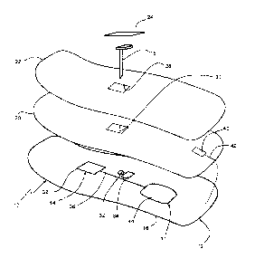
Referring to Fig. 1, a body-wearable medical sensor system 10 for continuous
glucose
monitoring (CGM) comprises a flexible electronics patch 12 which adheres to
the skin of a
user and includes a flexible printed circuitry (FPC) 14 which is applied
directly on a
flexible foil substrate 16, e.g. on a thin polymer film, such that the patch
12 is bendable
and/or stretchable to follow the contour of the skin.
As will be detailed further below, a user interface 17 is configured for
allowing the user to
control the device 10. The user interface 17 may be part of the FCP 14 or may
be a
separate body-wearable unit connected to the FCP 14. In this connection,
allowing the user
to control the device 10 means that functional components are provided on-body
such that
the user is able to directly interact with the device 10, e.g. by reading
information or
influencing a state of the device without remote control.
In certain embodiments, the system 10 further includes an electrochemical
needle sensor
18 which can be partially inserted into the skin, a flexible printed battery
20 (soft battery),
a top film 22 as a protective upper cover and a cover film 24 for the sensor
18 In the
prefabricated state prior to skin mounting, the foil substrate 16, printed
battery 20 and top
cover 22 are laminated on another to form a layered flexible assembly which
has an
adhesive 26 on the underside to attach the patch 12 to the user's skin. Then,
the distal part
of the needle sensor 18 can be inserted into the skin through openings 28, 30,
32 of the
layered assembly by means of an inserter aid (not shown), such that the
proximal sensor
part contacts a connector 34 of the FPC 14.
The FPC 14 carries flexible printed conducting pathways 36, capacitors,
resistors and
eventually rigid or semi-rigid electronic components 38, which are all
directly mounted on
the foil substrate 16. Further rigid elements may include the insertion
interface for the
sensor 8, which surrounds the insertion opening 32 at least partly, and
contact elements
such as connectors, printed carbon pills or conductive rubber for the sensor
electronic
connection. The more rigid components are distributed such that the FPC 14
overall
remains deformable to adapt its shape to a varying contour of the skin during
use. It may
also be conceivable that even processors, antennas for communication and
storage media
are integrated as flexible components, which would lead to a fully flexible
FPC.
- 14 -
In order to maintain sufficient flexibility, the foil substrate has a
thickness in the range of
10-250 microns. Preferably, polyimide or polyester films may be used. For
following a
skin contour under various conditions, it is also advantageous when the foil
substrate 16 is
stretchable in at least one direction by more of 20% of its initial length. In
case of
additional stacked layers like printed battery 20 and top film 22, an overall
thickness of
less than 2mm, preferably less than lmm should be aimed.
The printed battery 20 consists of functional electrode layers and electrolyte
materials, e.g.
a zinc manganese dioxide system, printed on a flexible foil substrate. An
antenna 40 for
wireless data transmission is arranged on top of the printed battery 20 such
that it is not
shielded by the metallic electrode layers. Then, a galvanic connection 42 to
the FPC 14 is
guided over the rim of the battery substrate. In specific configurations,
multiple antennas
may be used above and below the printed battery 20, or on the side thereof.
As outlined in fig. 1, the user interface 17 may comprise a display component
44 which
displays information related to the operation of the device 10. Such
information may be
related to the device status, measuring results, user guidance, warnings etc..
The display
component 44 may be readable through transparent or cut-out sections in the
battery 20
and cover foil 22. Purposively, the display component 44 is formed as a
flexible OLED
screen, and the screen is embedded on the foil substrate 16.
The user interface 17 may also comprise at least one switch which operates
an
electronic component of the FPC 14. The switch can be
realized by printed conducting
elements applied on the foil substrate 16 and operable by manual pressure
through the
cover foil 22, which may be marked appropriately. Such a switch may be used
for
power-on/off or emergency shutdown, or other user-initiated functions like
delivering
bolus doses to the body of the user by means of an insulin delivering patch
pump (not
shown). It is also conceivable that an integrated switch on the FPC 14 is
automatically
operable in dependence of a predefined switching condition, e.g. a reading
obtained by a
sensor.
Date Recue/Date Received 2021-01-11
- 15 -
Fig 2 shows a further embodiment in which the same numerals have been used for
same or
similar elements as described above. In this embodiment, the flexible printed
battery 20 is
arranged below the flexible printed circuits or circuitry 14. Consequently,
the underside of
the battery foil substrate is provided with the adhesive layer for adhering to
the skin.
Furthermore, the antenna 40 remains on the FPC 14, as it is not shielded by
the printed
battery 20 in the direction away from the user's body. The battery contact
points 48 are
through-connected to connection points on the FPC 14 for direct power supply.
Fig. 3 illustrates an embodiment of a body-wearable CGM system 10 in an
assembled state
mounted on a skin area . A data connection 52 between the flexible printed
circuitry 14
and a distant interface or display component 17 is provided preferably by
conductive
textiles. This allows to have the display 17 continuously visible on top of
the clothing.
Furthermore, a wireless connection 54 can be established via the integrated
antenna 40 to a
remote handheld data acquisition device 56, which can be provided as a
smartphone
equipped with an adapted software in the form of an app.
Date Recue/Date Received 2021-01-11