Note : Les descriptions sont présentées dans la langue officielle dans laquelle elles ont été soumises.
CA 03055601 2019-09-06
WO 2018/165712
PCT/AU2018/050235
A CONTAINERISED LNG LIQUEFACTION UNIT AND ASSOCIATED METHOD OF
PRODUCING LNG
TECHNICAL FIELD
A containerised LNG liquefaction unit and associate method of producing LNG
are
disclosed. The unit and method may be used to scale up or scale down LNG
production on an as needs basis by switching in or switching out additional
LNG
liquefaction units.
BACKGROUND ART
Large scale production of LNG requires enormous capex often in the order
several
tens of billion US dollars. For example Chevron's Gorgon project has a
reported cost in
the order of US$54 billion (http://wykiwrenercw-pubs.cornrautbÃoWcost-of-oomon-
inci:g.gp.), for a production capacity of 15.6 MTPA from three LNG trains.
An LNG train is an extremely complex structure comprising many interconnected
processing plant, systems and equipment including pre-treatment plants for
removal of
water, acid gas, mercury and C5+; a cryogenic heat exchanger; compressors;
gas,
electric or steam drives; and banks of air cooled heat exchangers.
In order to reduce capex it has been proposed to construct a LNG train as
several (for
example three to five) separate modules off-site which are subsequently
transported to
a production site and interconnected with each other. The separate modules can
be
inspected and tested prior to being transported production site. Such modular
trains
are proposed with the capacity in the order of 3-5 MPTA.
While it is believed that the modularisation of the LNG train in the above
manner may
assist in reducing overall capex it nonetheless remains in the order of
billions of US
dollars. Additionally, increasing production capacity is generally only
subsequently
achievable by installing further trains, and then only in "units" of 3-5 MPTA.
The above references to the background art do not constitute an admission that
the art
forms a part of the common general knowledge of a person of ordinary skill in
the art.
The above references are also not intended to limit the application of the LNG
liquefaction unit and method of producing LNG as disclosed herein.
1
CA 03055601 2019-09-06
WO 2018/165712
PCT/AU2018/050235
SUMMARY OF THE DISCLOSURE
In one aspect there is disclosed a LNG liquefaction unit comprising:
a LNG liquefaction plant; and
a transportable container wherein the LNG liquefaction plant is wholly
contained within the transportable container; and
one or more connectors supported on the container the one or more connectors
arranged to enable separate and isolated flow of services and fluids, the one
or more
connectors arranged to enable a feed stream gas to flow into the container, a
flow of
LNG out of the container and connection of the LNG liquefaction plant to an
external
source of electrical power.
In one embodiment the one or more connecters are further arranged to
facilitate a
removal of heat from the container. To this end the one or more connectors may
be
arranged to enable a flow of a heat transfer fluid into and out of the
container. The fluid
may for example be water.
In one embodiment the one or more connectors comprise a single multi-port
connector
enabling the simultaneous connection to corresponding conduits and couplings
for
each of the services and fluids.
In one embodiment the transportable container is hermetically sealed.
In one embodiment the connector includes a heat transfer fluid inlet port and
outlet port
enabling the removal of energy from the container.
In one embodiment the connector includes a drain enabling removal of gases or
liquids
from the container.
In one embodiment the connector includes one or more utility fluid port
enabling supply
of fluids to facilitate operation of equipment and/or instrumentation of the
LNG
liquefaction plant.
In one embodiment the container is filled with an inert fluid.
In one embodiment the inert fluid comprises nitrogen gas.
2
CA 03055601 2019-09-06
WO 2018/165712
PCT/AU2018/050235
In one embodiment the inert fluid when is pressurised to a positive pressure
relative to
atmospheric pressure.
In one embodiment the container is of an exterior size and shape of an ISO
shipping
container.
In one embodiment the unit comprises a monitoring system capable of monitoring
status and performance of the LNG liquefaction plant and providing remotely
accessible status and performance information pertaining to the liquefaction
unit.
In one embodiment the monitoring system is further capable of monitoring
environmental characteristics within the container.
In one embodiment the environmental characteristics include one or more of:
atmospheric pressure within the container; composition of the atmosphere in
the
container; temperature within the container; and temperature of one or more
selected
components of the LNG production plant.
In one embodiment the LNG production plant comprises a main cryogenic heat
exchanger (MCHE); and a refrigerant circuit for cycling a refrigerant through
the MCHE
the refrigerant circuit including at least one compressor and at least one
electric motor
for driving the at least one compressor.
In one embodiment the MCHE has an aspect ratio of where the width
and/or depth
is greater than the height.
In one embodiment the MCHE comprises two or more separate heat exchangers.
In one embodiment cooling duty of the MCHE is split between the two or more
separate heat exchangers
In one embodiment each separate heat exchanger has an aspect ratio of 1.
In one embodiment the MCHE is arranged to operate with a thermal stress of up
to
100 C per metre in a vertical direction.
3
CA 03055601 2019-09-06
WO 2018/165712
PCT/AU2018/050235
In one embodiment the MCHE comprises a 3-D printed heat exchanger.
In one embodiment wherein, the electric motor is arranged to rotate the at
least one
compressor a speed of at least 4,000 rpm or up to about 25,000RPM.
In one embodiment the at least one compressor comprises a low-pressure
compressor
and a high pressure compressor.
In one embodiment the at least one motor comprises a single motor which drives
both
the low-pressure compressor and the high pressure compressor.
In one embodiment the refrigerant circuit includes at least one separator for
separating
liquid and gas phases of the refrigerant, wherein the at least one separator
has an
aspect ratio of greater
In one embodiment the LNG liquefaction unit comprises at least one intercooler
in the
refrigerant circuit between the at least one compressor and the separator.
In one embodiment the container comprises a vent.
In one embodiment the LNG liquefaction unit comprises a kill port arranged to
facilitate
the injection of a material capable of preventing air from accumulating in, or
displacing
air from, the container.
In one embodiment the liquefaction plant comprises a pre-treatment facility
arranged to
remove one or more of: water, sour gases, mercury and carbon dioxide from the
feed
stream gas prior to liquefaction.
In one embodiment the LNG liquefaction plant is configured to produce up to
0.30
MTPA of LNG.
In one embodiment LNG liquefaction plant is configured to produce up to 0.10
MTPA of
LNG.
In a second aspect there is disclosed an LNG production plant comprising: a
plurality
of containerised LNG liquefaction units, each containerised LNG liquefaction
unit
arranged to produce a predetermined quantity of LNG in the order of 0.01 to
0.30
4
CA 03055601 2019-09-06
WO 2018/165712
PCT/AU2018/050235
MTPA; and a manifold system enabling connection between the plurality of
containerised LNG liquefaction units, and at least a feed stream of natural
gas, a
source of electrical power, and an LNG storage facility. In some embodiments
the
predetermined quantity of LNG in the order of 0.01 to 0.10 MTPA.
In one embodiment some of the plurality of LNG liquefaction units are stacked
on top
of each other.
In one embodiment the LNG production plant comprises at least one bank of
stacked
LNG liquefaction units and wherein the manifold system runs adjacent to the at
least
one bank of the LNG liquefaction units.
In one embodiment the at least one bank comprises at least two banks of the
stacked
LNG liquefaction units wherein the manifold system runs between mutually
adjacent
banks or about an outside of the banks.
In one embodiment the LNG liquefaction units and the manifold system are
arranged to
enable one face of every LNG liquefaction unit to be directly accessible to
the manifold
system.
In one embodiment each LNG liquefaction unit has a length Xm, a height Ym, and
a
width Zm wherein X>Y, and each bank has a length Lm, a height Hm, and a width
Wm,
where Lm > Wm and wherein in each bank, a length direction of each
liquefaction unit
is perpendicular to a length direction of the bank.
In one embodiment the LNG production plant comprises one or more cranes
configured to construct and de-construct each bank of LNG liquefaction units.
In one embodiment the crane comprises a gantry crane which spans a width of
the
LNG production plant and is capable of placing an LNG liquefaction unit in a
bank or
remove an LNG liquefaction unit from a bank.
In one embodiment each containerised LNG liquefaction unit comprises a closed
loop
refrigerant circuit.
5
CA 03055601 2019-09-06
WO 2018/165712
PCT/AU2018/050235
In one embodiment each containerised LNG liquefaction unit comprises an open
loop
heat transfer fluid circuit arranged to connect to the manifold system
enabling heat
transfer fluid to flow into and out of each containerised LNG liquefaction
unit.
In one embodiment the LNG production plant comprises a cooling facility in
fluid
communication with the manifold system and arranged to facilitate cooling of
the heat
transfer fluid.
In one embodiment the cooling facility comprises an air and/or water cooling
facility.
In one embodiment each containerised LNG liquefaction unit comprises an LNG
liquefaction unit according to the first aspect and its associated
embodiments.
In one embodiment the LNG production plant comprising a plurality of LNG
liquefaction
units according to the first aspect and its associated embodiments and a
manifold
system arranged to selectively connect, via the connector on each container,
one or
more of the LNG liquefaction units to: a feed stream gas; an LNG storage
facility; and
the source of electrical power, wherein the LNG production plant has a maximum
production capacity equal to the sum of the production capacity of each of the
liquefaction units in the production plant.
In a third aspect there is disclosed a method of producing LNG comprising
connecting
or disconnecting, to a natural gas feed stream, discrete incremental LNG
liquefaction
capacity as required to match mass flow rate of the natural gas in the feed
stream.
In one embodiment the method comprises connecting the discrete incremental LNG
liquefaction capacity in units of between 0.01 MTPA and 0.30 MTPA.
In one embodiment the method comprises providing the discrete incremental LNG
liquefaction capacity by way of one or more containerised LNG liquefaction
units
wherein each containerised LNG liquefaction unit is capable of being connected
to the
natural gas feed stream to receive at least a portion of the natural gas from
the feed
stream and producing from the portion of natural gas of a volume of LNG.
In one embodiment the method comprises monitoring operational status each of
the
containerised LNG liquefaction units to detect a failure of or fault in the
units, and upon
6
CA 03055601 2019-09-06
WO 2018/165712
PCT/AU2018/050235
detection of a failure or fault in a unit, disconnecting or otherwise
isolating the unit from
the natural gas feed stream.
In one embodiment the method comprises for each containerised LNG liquefaction
unit
detected as failed or having a fault, connecting a fresh containerised LNG
liquefaction
unit to the natural gas feed stream.
In one embodiment the method comprises transferring LNG produced by each
containerised LNG liquefaction unit to an LNG storage facility.
In one embodiment the method comprises circulating a heat transfer fluid
through the
containerised LNG liquefaction units connected to the natural gas feed stream
and
heat transfer fluid heat exchanger.
In one embodiment the method comprises providing the one or more containerised
LNG liquefaction units as liquefaction units in accordance with first aspect
and its
associated embodiments.
In a fourth aspect there is disclosed a method of supplying LNG at a
temperature of
about -161 C a pressure of about 1 bar comprising:
producing, at a fixed location, LNG at a temperature higher than -161 C and a
pressure of greater than one bar;
transferring the produced LNG to transport vessel having pressurised storage
tanks for holding the produced LNG; and
while sailing the transport vessel to a destination port chilling the LNG to
about
-161 and reducing containment pressure of the LNG to about 1 bar.
In one embodiment the method comprises producing the LNG in one or more
containerised LNG liquefaction units wherein each containerised LNG
liquefaction unit
is configured to produce LNG at a temperature higher than -161 C and a
pressure of
greater than one bar.
In on embodiment the method comprises producing the LNG at a fixed location
comprises producing the LNG accordance with the third aspect and its
associated
embodiments
7
CA 03055601 2019-09-06
WO 2018/165712
PCT/AU2018/050235
In a fifth aspect there is disclosed a method of constructing an LNG
production plant at
a production site comprising: connecting or disconnecting, to a natural gas
feed
stream, discrete incremental LNG liquefaction capacity as required to match
mass flow
rate of the natural gas in the natural gas feed stream.
In one embodiment connecting discrete incremental LNG liquefaction capacity
comprises transporting to the production site one or more containerised LNG
liquefaction units wherein each of the units is capable of producing from the
natural
gas feed stream the predetermined volume of LNG; and connecting the one or
more
containerised LNG liquefaction units to the natural gas feed stream.
In one embodiment the method comprises stacking the one or more containerised
LNG
liquefaction units to form one or more banks of stacked containerised LNG
liquefaction
units.
In one embodiment the method comprises autonomously stacking the one or more
containerised LNG liquefaction units to form the one or more banks.
In one embodiment the method comprises connecting the containerised LNG
liquefaction units to a heat transfer fluid circuit arranged to enable a flow
of a heat
transfer fluid through each of the connected containerised LNG liquefaction
units and
an external heat exchanger.
In one embodiment the method comprises connecting the one or more
containerised
LNG liquefaction units connecting a power supply.
In one embodiment the method comprises connecting the one or more
containerised
LNG liquefaction units to a LNG storage facility.
In one embodiment the method comprises connecting the one or more
containerised
LNG liquefaction units to a supply of an inert gas.
In one embodiment the method comprises autonomously connecting one or more of
the power supply, LNG storage facility, and suppliers in a gas to the one or
more
containerised LNG liquefaction units.
8
CA 03055601 2019-09-06
WO 2018/165712
PCT/AU2018/050235
In one embodiment the method comprises simultaneously connecting the power
supply, the heat transfer fluid circuit, and the supply of inert gas to the
one or more
containerised LNG liquefaction units.
In a sixth aspect there is disclosed a refrigeration system for facilitating
liquefaction of
natural gas comprising a volume of a single mixed refrigerant (SMR) and a
closed loop
refrigeration circuit through which the SMR circulates as a plurality of
refrigerant
streams having at least a first LMR refrigerant stream, a first heat exchanger
main
refrigerant stream, a subcooled LMR stream and a second heat exchanger main
refrigerant stream, the circuit having first and second heat exchangers and at
least one
compressor for compressing the SMR;
wherein the first heat exchanger is arranged to cool the first LMR refrigerant
stream against the first heat exchanger main refrigerant stream to produce the
subcooled LMR refrigerant stream;
the second heat exchanger is arranged to cool a natural gas feed stream
against the second heat exchanger main refrigerant stream to produce liquefied
natural
gas wherein the second heat exchanger main refrigerant stream is derived at
least in
part from the subcooled LMR stream; and
wherein at least the first and second heat exchanger main refrigerant streams
are circulated by pressure differential alone thought the refrigeration system
created by
the at least one compressor.
In one embodiment the first heat exchanger is configured so that the first
heat
exchanger main refrigerant stream flows through the first heat exchanger and
vaporises by heat transfer with the first LMR refrigerant stream to produce a
first
vapour refrigerant stream.
In one embodiment the subcooled LMR stream is split to form a first expanded
stream
and a second expanded stream and wherein the first heat exchanger main
refrigerant
stream comprises, at least in part, the first expanded stream and the second
heat
exchanger main refrigerant stream comprises, at least in part, the second
expanded
stream.
In one embodiment the plurality of refrigerant streams includes a first HMR
refrigerant
stream which is cooled against the second heat exchanger main refrigerant
stream in
the second heat exchanger to produce a subcooled HMR stream.
9
CA 03055601 2019-09-06
WO 2018/165712
PCT/AU2018/050235
In one embodiment the subcooled HMR stream is split and expanded to form a
third
expanded stream and a fourth expanded stream wherein the third expanded stream
is
combined with the second expanded stream to form the second heat exchanger
main
refrigerant stream; and the fourth expanded stream is combined with the first
expanded
stream to form the first heat exchanger main refrigerant stream.
In one embodiment the second heat exchanger main refrigerant stream is
vaporised in
the second heat exchanger to form a second vapour refrigerant stream.
In one embodiment the refrigeration circuit comprises a first separator which
receives
the first vapour refrigerant stream and the second vapour refrigerant stream.
In one embodiment at least one compressor comprises a low-pressure compressor,
a
high pressure compressor and the refrigerant system includes a second
separator in
fluid communication between the low-pressure compressor and the high pressure
compressor and a vapour from the second separator is compressed by the high
pressure compressor to form the first LMR refrigerant stream.
In a first embodiment a bottoms liquid from the second separator forms the
first HMR
refrigerant stream.
In one embodiment the first and second vapour refrigerant streams are
compressed by
the first compressor.
In a second embodiment the refrigerant system comprises a third separator in
fluid
communication with the high pressure compressor and wherein a vapour from the
third
separator form the first LMR stream and bottoms liquid form the third
separator forms
the first HMR stream.
In a seventh aspect there is disclosed a refrigeration system for facilitating
liquefaction
of natural gas comprising a volume of a single mixed refrigerant (SMR) and a
closed
loop refrigeration circuit through which the SMR circulates as a plurality of
refrigerant
streams having at least a first LMR refrigerant stream, a first heat exchanger
main
refrigerant stream, a subcooled LMR stream and second heat exchanger main
refrigerant stream, the circuit having first and second heat exchangers;
CA 03055601 2019-09-06
WO 2018/165712
PCT/AU2018/050235
wherein the first heat exchanger is arranged to cool the first LMR refrigerant
stream against the first heat exchanger main refrigerant stream to produce the
subcooled LMR refrigerant stream;
the second heat exchanger is arranged to cool a natural gas feed stream
against the second heat exchanger main refrigerant stream to produce liquefied
natural
gas wherein the second heat exchanger main refrigerant stream is derived at
least in
part from the subcooled LMR stream; and
wherein at least the first LMR refrigerant stream is a mixed phase refrigerant
stream.
In one embodiment the first heat exchanger main refrigerant stream is a mixed
phase
refrigerant stream.
In one embodiment the second heat exchanger main refrigerant stream is a mixed
phase refrigerant stream.
In one embodiment the composition of the single mixed refrigerant in the first
heat
exchanger main refrigerant stream flowing into the first heat exchanger is
different to
the composition of the single mixed refrigerant in the second heat exchanger
main
refrigerant stream flowing into the second heat exchanger.
In an eighth aspect there is disclosed a refrigeration system for facilitating
liquefaction
of natural gas comprising a volume of a single mixed refrigerant (SMR) and a
closed
loop refrigeration circuit through which the SMR circulates as a plurality of
refrigerant
streams, the refrigeration circuit having at least one compressor and at least
two heat
exchangers spaced from each other, wherein a first heat exchanger is arranged
to cool
the SMR against itself to produce a precooled LMR refrigerant stream, and the
second
heat exchanger is arranged to cool the natural gas against a second heat
exchanger
main refrigerant stream sourced in part from the precooled LMR refrigerant
stream to
produce liquefied natural gas.
In a ninth aspect there is disclosed a refrigeration system for facilitating
liquefaction of
natural gas comprising a volume of a SMR and a closed loop refrigerant circuit
through
which the SMR flows, the circuit having two spaced apart heat exchangers, the
SMR
circulating as a first heat exchanger main refrigerant stream and a first LMR
stream
provided at separate inlets to the first heat exchanger and a second heat
exchanger
main refrigerant stream and a first HMR refrigerant stream provided at
separate inlets
11
CA 03055601 2019-09-06
WO 2018/165712
PCT/AU2018/050235
to the second heat exchanger, wherein composition of the SMR refrigerant
streams at
each of the inlets is different from each other.
In an embodiment of any one of the sixth to ninth aspects one or both first
heat
exchangers and the second heat exchangers has an aspect ratio of greater than
one.
(i.e. "horizontal" heat exchangers).
In an embodiment of any one of the sixth to ninth aspects the SMR refrigerant
is
circulated through the heat exchangers solely by pressure differential created
by the
compressors.
In a tenth aspect there is disclosed a liquefaction system comprising:
a refrigerant circuit having least a first heat exchanger and a second
different
heat exchanger;
a volume of a SMR which flows through the circuit and includes a light and a
heavy mixed refrigerant fraction;
wherein the first heat exchanger is cooled by a SMR stream having a first
proportion of the light and heavy refrigerant fractions and the second heat
exchanger is
cooled by a SMR stream with a second different proposition of the light and
heavy
refrigerant fractions. An example of this arrangement is shown in Figure 5
where the
valve shown in phantom is included.
In one embodiment the proportion of the heavy refrigerant fraction in the SMR
stream
for either one of the first or the second heat exchangers is zero. This is
exemplified by
the arrangement in Figure 5 where the valve shown in phantom is omitted.
In an eleventh aspect there is disclosed a liquefaction system comprising:
a refrigerant circuit having least a first heat exchanger and a second heat
exchanger;
a volume of a SMR which flows through the circuit and includes a light and a
heavy
mixed refrigerant fraction; and
a hot stream of fluid divided into at least a first hot stream portion and a
second
hot stream portion wherein the first hot stream portion is directed to flow
through the
first heat exchanger, and the second hot stream portion is directed to flow
through the
second heat exchanger. An example of this arrangement is shown in Figures 7
and 8.
In one embodiment hot stream that is divided is the natural gas stream that is
being
liquefied by the system. This is also exemplified in Figures 7 and 8.
Additionally in this
12
CA 03055601 2019-09-06
WO 2018/165712
PCT/AU2018/050235
embodiment the first and second heat exchangers may be different from each
other.
Throughout this specification except where the context requires otherwise due
to
express language or necessary implication, the expressions "different heat
exchangers" or "different types of exchanger" and variations such as
"different
exchangers" are intended to include at least the following difference between
heat
exchangers:
= Different number of passes or channels;
= Same number of passes or channels but where the exchangers are of
different
size;
= Operating with refrigerant streams at one or any combination of two or
more of
(a) different pressures; (b) different flow rates; and (c) different
compositions
In a twelfth aspect there is disclosed a liquefaction system comprising:
a refrigerant circuit having least a first heat exchanger and a second heat
exchanger;
a volume of a SMR which flows through the circuit and includes a light and a
heavy mixed refrigerant fraction;
wherein the first heat exchanger is cooled by a SMR stream having a first
proportion of the light and heavy refrigerant fractions and the second heat
exchanger is
cooled by a SMR stream with a second different proposition of the light and
heavy
refrigerant fractions; anda hot stream of fluid is divided into at least a
first hot stream
portion and a second hot stream portion wherein the first hot stream portion
is directed
to flow through one of the first and second heat exchangers, and the second
hot
stream portion is directed to flow through another of the first and second
heat
exchanger. An example of this arrangement is shown in Figure 10. Additionally,
in one
embodiment of this aspect the first and second heat exchangers may be
different from
each other.
BRIEF DESCRIPTION OF THE DRAWINGS
Notwithstanding any other forms which may fall within the scope of the LNG
liquefaction unit and associate method of producing LNG as set forth in the
Summary,
specific embodiments will now be described, by way of example only, with
reference to
becoming drawings in which:
13
CA 03055601 2019-09-06
WO 2018/165712
PCT/AU2018/050235
Figure 1 is a schematic isometric view of one embodiment of the disclosed
containerised LNG liquefaction unit;
Figure 2 is an isometric view from one angle of plant and equipment of the
containerised LNG liquefaction unit shown Figure 1;
Figure 3 is an isometric view from a second angle of the plant and equipment
shown in
Figure 2;
Figure 4 is an isometric view from a third angle of the plant and equipment
shown in
Figure 2;
Figure 5 is a flow diagram of one embodiment of the LNG liquefaction unit;
Figure 6 is a flow diagram of a second embodiment of the LNG liquefaction
unit;
Figure 7 is a flow diagram of a third embodiment of the LNG liquefaction unit;
Figure 8 is a flow diagram of a fourth embodiment of the LNG liquefaction
unit;
Figure 9 is a flow diagram of a fifth embodiment of the LNG liquefaction unit;
Figure 10 is a flow diagram of a sixth embodiment of the LNG liquefaction
unit;
Figure 11 is a flow diagram of a seventh embodiment of the LNG liquefaction
unit; and
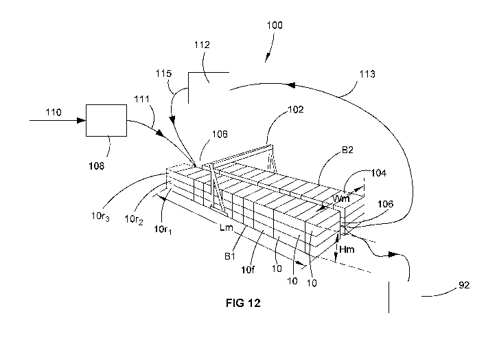
Figure 12 is a schematic representation of a 9.9 MPTA LNG production facility
incorporating 200 of the disclosed LNG liquefaction units wherein each
liquefaction unit
has a nominal LNG production capacity of 0.05 MPTA.
DETAILED DESCRIPTION OF SPECIFIC EMBODIMENTS
Referring to the accompanying Figures an embodiment of the containerised LNG
liquefaction unit 10 comprises an LNG liquefaction plant 12 (shown in Figures
2-4) and
a transportable container 14 (shown in Figure 1). The LNG liquefaction plant
12 is
wholly contained within the transportable container 14. In the illustrated
embodiment a
plurality of connectors 16a -16f (hereinafter referred to in general as
"connectors 16")
14
CA 03055601 2019-09-06
WO 2018/165712
PCT/AU2018/050235
are supported on the container 14 to enable the separate and mutually isolated
flow of
services, fluids and utilities into and/or out of the container 14.
Each of the connectors 16 is provided on a common wall 11 of the container 14.
The
connectors include but are not limited to:
= a feed gas inlet connector 16a enabling a feed stream of gas for
liquefaction to
be fed to the plant 12;
= a LNG outlet connector 16b enabling LNG produced by the plant 12 to exit
the
container 14, for example to flow into a storage tank;
= a power connector 16c providing electrical power to the equipment forming
the
plant 12;
= an inert gas inlet connector 16d, enabling an inert gas such as but not
limited to
nitrogen gas to flow into the container 14 to provide an inert environment
and/or
for operating instrumentation and controls;
= a heat transfer fluid inlet connector 16e to enable a heat transfer fluid
such as
water to be provided to one or more intercoolers or the other heat exchanger
within the container 14;
= a heat transfer fluid outlet connector 16f to enable the heat transfer
fluid to pass
out of the container 14 for example to a heat rejection plant and for possible
recirculating to the heat transfer fluid inlet 16e, thereby enabling heat
energy to
be removed from the container 14;
= a drain connector 16g to enable removal of unwanted liquids from the
container
14 for commissioning the unit 10, de-commissioning the unit prior to
maintenance and/or used for emergency response, e.g. blowdown of
hydrocarbons;
= a vent 16h for the removal of unwanted vapours or release of
hydrocarbons;
= a kill port connector (not shown) enabling the injection of a gas, liquid
or slurry
for the purposes of fully shutting down and rendering harmless the LNG plant
12.
The container 14 may be hermetically sealed to prevent uncontrolled flow of
fluid into
and out of the container 14. Further, the container 14 may be provided with a
positive
pressure relative to the outside environment
It may be advantageous but not essential that the container 14 is in the
general shape
and configuration, and moreover has an exterior size and shape, of an ISO
container.
CA 03055601 2019-09-06
WO 2018/165712
PCT/AU2018/050235
ISO containers come in a wide range of standard dimensions are handled all
over the
world at shipping ports as well as on rail and road transport vehicles.
Accordingly, the
infrastructure for the transportation and movement of such containers is
readily
available and easily replicated. ISO containers are available in standard
lengths from
10 foot up to 53 foot (about 3m to 16m). For most standard lengths there is
also a
range of container sizes varying in width or height. Some embodiments of the
disclosed containerised LNG liquefaction unit 10 are arranged to fit within a
standard
ISO 40 foot (12 m) container. A standard ISO container while of suitable
dimensions is
likely to require structural reinforcement and strengthening to accommodate
the weight
of the liquefaction unit. By way of comparison standard ISO 40 foot container
has a
rated maximum capacity of about 30 tonnes whereas the weight of the
liquefaction unit
12 is likely to be in the order of 80-90 tonnes.
Referring now specifically referring to Figures 2-4 the liquefaction unit 12
utilises a
single mixed refrigerant (SMR) process. The liquefaction unit 12 uses a main
cryogenic
heat exchanger (MCHE) whose duty cycle is split across two separate, and in
this
instance different, cryogenic heat exchangers 17 and 18. (The being that the
heat
exchanger 17 as two passes all channels whereas the heat exchanger 18 has
three.)
As will be explained in greater detail later the heat exchanger 17 provides
precooling of
the refrigerant whereas the heat exchanger 18 effects liquefaction of the
natural gas
feed.
The heat exchangers 17 and 18 may be of various types including but not
limited to
plate heat exchangers or 3D printed heat exchangers. Irrespective of the
technology
used in the present embodiment the heat exchangers have an aspect ratio of
meaning that their length L is greater than their height H. This is the exact
opposite to
conventional MCHEs where the height dimension is greater than its length/width
dimension. Additionally, the heat exchangers 17 and 18 are required to handle
a
thermal stress in the order of at least 90 -100 C/m of height. For example, in
one
embodiment of a SMR circuit shown in Fig 5, the heat exchanger 17 has a LMR
inlet
feed at the ambient temperature (e.g. about 25 C) and an expanded main
refrigerant
feed of around -159 C, with a heat exchanger itself having a height dimension
H of
less than about 2 m. The heat exchanger 17 requires a minimum of two channels
while
the exchanger 18 requires a minimum of three channels.
The liquefaction unit 12 is provided with a low-pressure compressor 20 and a
high-
pressure compressor 22. The compressors 20, 22 are driven by a common electric
16
CA 03055601 2019-09-06
WO 2018/165712
PCT/AU2018/050235
drive 23. The compressors 20, and 22 are hermetically sealed. Vapour phase
refrigerant is supplied to the inlet of the low-pressure compressor 20 via a
separator
24. The low-pressure compressor 20 compresses the vapour to around 15 bar and
a
temperature of around 100 C. The compressed refrigerant is passed through an
intercooler 26 (where cooling is provided by heat exchange with a water flow)
reducing
the temperature of the compressed refrigerant to around 25 C.
The compressed refrigerant is fed to a separator 28. The separator 28 is in a
horizontal
disposition rather than the common vertical disposition. To provide more
distinct
separation between vapour and liquid phases within the separator 28, owing to
its
horizontal disposition, separator 28 comprises a vapour vessel 29a (see Fig
2), and a
liquid vessel 29b which are in fluid communication with each other via a
manifold 29c.
The vapour phase from the separator 28 is fed to the inlet of the high-
pressure
compressor 22 from the vapour vessel 29a. The compressor 22 compresses the
refrigerant which is cooled by flow through an aftercooler 30 (which also
provides
cooling by heat exchange with a water flow) to about 25 C and supplied as a
dual
phase light mixed refrigerant (LMR) via a conduit 32 to an inlet 34 of the
heat
exchanger 17. The liquid phase from the separator 28 is supplied via liquid
vessel 29b
and conduit 36 as a heavy mixed refrigerant (HMR) to an inlet 38 of the second
heat
exchanger 18.
The LMR provided at the inlet 34 is cooled in the heat exchanger 17 against a
first heat
exchanger main refrigerant stream provided via conduit 40 to inlet 42 of heat
exchanger 17. The LMR is cooled and exits the heat exchanger 16 via a conduit
44
where it is fed to a splitter 46. The splitter 46 splits the cooled LMR into:
a first stream
which flows through conduit 52 to a first expansion valve 52; and, a second
stream
which flows through conduit 54 to a second expansion valve 56. The flow rate
between
the first and second streams in this embodiment is not the same but rather is
on a ratio
of about 1.5:1 (i.e. the flow rate through the conduit 50 is about 1.5 times
that flowing
through the conduit 54).
The HMR provided at the inlet 38 is cooled in the second heat exchanger 18
against a
second heat exchanger main refrigerant stream provided by a conduit 58 to an
inlet 60.
The HMR is cooled and exits the heat exchanger 18 via a conduit 62 and flows
to a
splitter 64. The splitter 64 splits the cooled HMR into a first stream which
flows through
a conduit to a third expansion valve 68 and a second stream which flows
through a
17
CA 03055601 2019-09-06
WO 2018/165712
PCT/AU2018/050235
conduit to a fourth expansion valve 72. The flow rate between the streams
passing
through conduit 66 and 70 is on a ratio of about 1:13 (i.e. the flow rate to
the expansion
valve 72 is 13 times that of the flow rate to the expansion valve 68).
The expansion valve 52 provides a first expanded refrigerant flow through
conduit 74.
The expansion valve 56 provides a second expanded refrigerant flow through
conduit
76. The third expansion valve 68 provides a third expanded refrigerant flow
through
conduit 78. The fourth expansion valve 72 provides a fourth expanded
refrigerant flow
through conduit 80. The first heat exchanger main refrigerant stream flowing
through
the conduit 40 to the inlet 42 is a combination of the first and fourth
expanded
refrigerant streams provided via conduits 74 and 80. The second heat exchanger
main
refrigerant stream flowing through conduit 58 to the inlet 60 comprises the
combination
of the second and third expanded refrigerant flow is provided via conduits 76
and 78
respectively.
The relative mass flow rates between the first and second heat exchanger main
refrigerant flows is around 2:1 (i.e. the flow mass rate into the inlet 42 is
about twice
that of the mass flow rate at the inlet 60).
Evaporated refrigerant leaves the first heat exchanger 17 via outlet 63 and
flows
through conduit 65 to the first separator 24. Evaporated refrigerant leaves
the second
heat exchanger 18 via outlet 67 and flows through conduit 69 and then conduit
65 to
the first separator 24.
A natural gas feed stream is provided by the connector 16a to an inlet 82 of
the second
heat exchanger 18 at a temperature of about 25 C and pressure of about 80
bar. The
natural gas feed stream is liquefied within the heat exchanger 18 and exits as
LNG at
an outlet 84 at a temperature of about -157 C and pressure of around 78 bar.
The
LNG flows through conduit 86 to expansion valve 88 wherein it is cooled to a
temperature of between about -161 C to -162 C and depressurised to one bar
then
subsequently fed to the connector 16b. A conduit 90 connected to the connector
16b
feeds the LNG to an LNG storage tank 92 which is outside of and remote from
the
container 14. In a minor variation of this arrangement the valve 88 may be
outside of
the container 14.
While the liquefaction unit 10 utilises a single mixed refrigerant the
composition of the
refrigerant in each of the heat exchangers 17, 18 is different. This arises
because the
18
CA 03055601 2019-09-06
WO 2018/165712
PCT/AU2018/050235
LMR and HMR provided at the inlet 34 and 38 respectively have components of
the
refrigerant in different proportions in vapour and liquid phases. The LMR
provided at
the inlet 34 has refrigerant in both liquid and vapour phases where the HMR is
provided at the inlet 38 in a liquid phase only.
In the embodiment of the plant 12 shown in Figure 5 the expansion valve 68 is
shown
in phantom line to indicate that this is an optional valve. When this valve is
included
there is then to valve's feeding each of the heat exchangers 17, 18 so that
both can
receive a mixture of two refrigerant fractions (i.e. LMR and HMR). Where the
ideal
refrigerant composition for one exchanger is 100% of the lighter fraction,
then the valve
68 can be omitted for simplicity.
Figure 2 also illustrates a conduit 94 which provides heat exchanger fluid in
the form of
water to the intercooler 26 and after cooler 30. The conduit 94 is in fluid
communication
with the connector 16e. A conduit 96 feeds the spent heat exchanger fluid from
the
coolers 26 and 32 to the connector 16f.
In the present embodiment motor 23 is a single motor having coaxial drive
shafts at
opposite ends for driving the compressor is 20 and 22. Ideally the compressors
20 and
22 are arranged to be driven at the same speed thereby avoiding the need for
one or
more gearboxes. However, embodiments where the compressors are driven at
different speeds by the same motor via the use of gearboxes are also
contemplated.
Indeed, as discussed later below is also possible for the compressors 20 and
22 to be
driven by different motors.
Each unit 10 is provided with a monitoring system (not shown) capable of
monitoring
status and performance of the LNG liquefaction plant 12 and providing remotely
accessible status and performance information pertaining to the liquefaction
unit. The
monitoring system may further monitor environmental characteristics within the
container. The environmental characteristics include one or more of, but are
not limited
to: pressure of the atmosphere within the container 14; composition of the
atmosphere
in the container 14; atmospheric temperature within the container 14; and
temperature
of one or more selected components of the LNG production plant.
Figure 6 shows an embodiment of the SMR circuit for an alternate liquefaction
plant
12a. In Figure 6 the same reference numerals are used as for Figure 5 to
denote the
same features. The main differences between the liquefaction plants 12 and 12a
are:
19
CA 03055601 2019-09-06
WO 2018/165712
PCT/AU2018/050235
= The use of a three channel heat exchanger 17a in the plant 12a in
comparison
to the two channel heat exchangers 17 of plant 12. Thus, in this embodiment of
the plant 12a has to similar heat exchangers.
= Incorporation of a third separator 31 in the plant 12a in series
connection with
the high-pressure compressor 22 and the water cooler 30.
= Providing the bottoms liquid from the separator 28 as a second HMR stream
which is provided to an inlet 73 of the heat exchanger 17a.
= An expansion valve 71 which receives and expands the cooled second HMR
refrigerant stream from the heat exchanger 17a, and adds this to the first
heat
exchanger main refrigerant stream flowing in conduit 40 to the inlet 42.
Vapour from the separator 31 constitutes the light mixed refrigerant (LMR)
which is fed
via a conduit 32 to inlet 34 of the heat exchanger 17a. The bottoms liquid
from the
separator 31 provides the first HMR refrigerant stream which is fed to the
inlet 38 of the
second heat exchanger 18. This is cooled in the second heat exchanger 18
against a
second heat exchanger main refrigerant stream provided by a conduit 58 to the
inlet 60
to produce a subcooled first HMR stream.
In both liquefaction plants 12 and 12a the refrigerant is circulated solely by
pressure
differential generated by the compressors 20, 22. No pump is required in the
plants 12,
12a or corresponding units 10 for circulating of the refrigerant.
Figure 7 shows an embodiment of the SMR circuit for an alternate liquefaction
plant
12b. In Figure 7 the same reference numerals are used as for Figure 6 to
denote the
same features. The main differences between the liquefaction plants 12a and
12b are:
= The plant 12b has two four channel (or four pass) heat exchangers 17b and
18b.
= At least one hot feed stream, in this drawing the natural gas stream
provided at
the connector 16a is divided at splitter 120 and feed to both heat exchangers
17b and 18b to the inlets 82x and 82y respectively. This division can be
controlled including dynamically controlled the splitter or additional valves
to
different heat exchangers.
CA 03055601 2019-09-06
WO 2018/165712
PCT/AU2018/050235
= The natural gas feeds are liquefied by passing through the heat
exchangers
17b, 18b and combined at a mixer 122, there after passing through expander
88 and into the storage facility 92.
= The proportion of the split to feed to natural gas to heat exchangers 17a
and
17b can be varied (including dynamically varied) to control the duty and shape
of the composite curve for each of the heat exchangers 17a, 17b.
= HMR from separator 28 is fed to inlet 73 of heat exchanger 17b, and HMR from
separator 31 is fed to the inlet 38 of the heat exchanger 18b (as in the
liquefaction unit 12a).
= The LMR are from the separator 31 is divided at splitter 124 and fed to
the inlet
34 of heat exchanger 17b and the inlet 126 of heat exchanger 18b.
= The LMR and HMR passing through the heat exchangers 17b and 18b are
combined at a mixer 128 to produce SMR which flows through conduit 130 and
is subsequently divided at splitter 132 into a first SMR stream flowing
through
conduit 40 to the inlet 42 of heat exchanger 17b, and a second SMR stream
flowing through conduit 58 to the inlet 60 of the heat exchanger 18b.
= The respective SMR streams are then combined at a mixer 131 and fed to
the
separator 24 for compression of the low-pressure compressor 20 and high-
pressure compressor 22.
= It is possible with this arrangement for the heat exchangers 17b and 18b
to be
physically different from each other.
A possible modification of the liquefaction unit 12b shown Figure 7 is to
provide a
second mixer in parallel with the mixer 128 is also fed with the LMR and HMR
from the
heat exchangers 17b and 18b by valve controlled splitters. For example, a
valve
controlled splitter can be replaced in the conduit 134 to enable the HMR from
the heat
exchanger 17b to be provided in a user controlled ratio to the mixer 128 and
the
second mixer (not shown). This can be done for each of the LMR/HMR lines from
the
heat exchangers 17b, 18b. The mixer 128 can be arranged to feed and MR through
conduit 58 to the heat exchanger 18b, while the second mixer can feed MR
through the
21
CA 03055601 2019-09-06
WO 2018/165712
PCT/AU2018/050235
conduit 40 to the exchanger 17b. Now the MR fed to the heat exchangers 17b and
18b
(in particular the ratio of LMR/HMR in each MR feed) can be varied. This
includes
having zero HMR in one of the "MR" feed stream.
The significance of this is that it facilitates the use of heat exchangers of
different
characteristics (i.e. when multiple heat exchangers are used it is not a
requirement for
all to be identical). Possible benefits of the use of two non-identical or
different heat
exchangers benefit of this of using at least two heat exchangers is explained
below.
For efficiency in refrigeration processes, as persons skilled in the art would
recognise,
the refrigerant heat release curve should match that of the streams to be
cooled down,
with a small offset to provide the temperature driving force.
The traditional approach for making LNG is to use multi-steam heat exchangers,
with
multiple hot streams being cooled down by a single refrigerant stream.
The composition and conditions of the refrigerant stream are deliberately
chosen to
produce a temperature profile to match that of the combined composite curve of
the
multiple hot streams. The multiple hot streams include both the natural gas
and the
high pressure refrigerant itself.
In situations where the required throughput exceeds what can be constructed in
a
single heat exchanger, multiple identical heat exchangers are typically used.
For
example, two parallel coil-wound heat exchangers. To ensure the correct flows
through
each heat exchanger, it is customary to use symmetrical piping. This ensures
that the
flow path through one heat exchanger is more restricted than the parallel path
through
the other. In some cases, balancing valves may also be employed as a backup
measure to bias the flow to account for manufacturing tolerances.
In the case of plate-fin heat exchangers where multiple identical (or mirror-
imaged)
cores (e.g. 4-10 cores) are used, large diameter headers are used to ensure
that the
pressure drop through each core is practically identical.
In both cases the use of identical cores means that every service needs to be
piped to
each individual heat exchanger section. This leads to a restrictive and
expensive piping
design, and more complication of the heat exchangers themselves.
22
CA 03055601 2019-09-06
WO 2018/165712
PCT/AU2018/050235
An alternative is to cool down each of the hot streams down in multiple, non-
identical
heat exchangers. This can reduce the number of connections to the multiple
heat
exchangers and also remove the need for symmetrical piping.
The downside of using non-identical heat exchangers is that each will have a
different
composite curve for the streams to be cooled by the refrigerant. Thus, the
refrigerant
cooling curve will not be fully optimised. The above described modified form
of the
present embodiment (i.e. with the second mixer) aims to overcome this concern
in two
different ways. Firstly, the refrigerant composition used in each heat
exchanger 17b,
18b may be adjusted independently for each heat exchanger. This composition
change
alters the heating curve of the cold refrigerant in each exchanger, allowing
it to better
match the hot composite curve in each section. Secondly splitting one of the
hot
streams and passing it through more than one heat exchanger, both the duty and
the
shape of the composite curve may be adjusted. Thus, it is possible to adjust
the shape
of the hot composite curves in order to make them as similar as possible. This
allows a
single refrigerant composition to be used to cool both heat exchangers without
compromising the efficiency.
Finally, the combination of the two approaches can be used ¨ splitting at
least one of
the hot streams to create hot composite curves in each exchanger that are as
similar
as possible and furthermore adjusting the composition of refrigerant supplied
to each
heat exchanger to match the temperature profile in each heat exchanger. In the
example shown in Figure 7 the split of natural gas natural gas stream (which
may
constitute a "hot stream") fed to the heat exchangers 17b and 18b may be
varied for
this purpose. It will also be understood that the HMR (also constituting a
"hot stream")
fed to the respective heat exchangers 17b and 18b will be different at least
in terms of
pressure and temperature from each other. Finally, the split ratio of LMR fed
to the
respective heat exchangers 17b and 18b may also be varied at the splitter 124
for
example by the use of valves.
In order to adjust the composition of the refrigerant, the ratio of the flows
between
"heavy" and "light" refrigerant fractions may be adjusted. This the average
molecular
weight of the mixed refrigerant can be controlled, both in the design phase
and
dynamically in operation.
23
CA 03055601 2019-09-06
WO 2018/165712
PCT/AU2018/050235
Therefore, in summary the embodiment of the liquefaction plant 12 shown in
Figure 7
enables the heat exchangers 17b, 18b (be they identical or deliberately
different) to be
cooled by SMR streams of different composition.
Figure 8 illustrates a liquefaction plant 12c which is a simplified form of
the plant 12b
shown in Figure 7. The simplification is brought about by the deletion of the
discharge
separator 31 and consequentially the ability to replace the two four pass
exchangers
with two three pass exchangers 17c and 18c. As in the plant 12b, the plant 12c
provides the ability to split (unevenly in this case) the natural gas between
two heat
exchangers 17c, 18c, to enable
substantially the same hot-side cooling curve in both exchangers. Therefore,
the same
composition of refrigerant can be sent to both heat exchangers with minimal
loss of
efficiency.
The bottoms liquid from the separator 28 constitutes HMR that is passed
through the
heat exchanger 17c and subsequently expanded by passing through valve V1. The
compressed refrigerant after passing through high pressure compressor 22 and
cooler
30 is fed to exchanger 18c and subsequently expanded through the valve V2. The
expanded refrigerants from valves V1 and V2 are combined to form the first and
second mixed refrigerant feeds to the inlet 42 and 58 of the heat exchangers
17c and
18c.
Unlike the arrangement in the plant 12 of Fig 5, the proportion of the
refrigerant which
passes through each example is not variable in operation. The cold refrigerant
flows
will balance based upon the pressure drop through each path. The ability to
control the
natural gas flows through each exchanger, enables compensation and ensures
both
exchangers can share the load.
While the liquefaction plants 12, 12a, 12b, and 12c are each shown as having
two heat
exchangers. However, embodiments are possible for incorporation in the unit 10
which
have a single heat exchanger. One such example is the liquefaction unit 12d
shown in
Figure 9. In Figure 9 the same reference numerals are used as for Figure 6 to
denote
the same features. The substantive differences between the liquefaction plant
12d and
plant 12a, or significant features of the liquefaction plant 12d are
summarised as
follows:
= The plant 12c has a single four pass heat exchanger 17.
24
CA 03055601 2019-09-06
WO 2018/165712
PCT/AU2018/050235
= The MR compression circuit for the plant 12d is the same as that for
plant 12a,
having an initial separator 24, low pressure compressor 20, intercooler 26,
second separator 28, high pressure compressor 22, intercooler 30 and a final
separator 31.
= Bottoms liquid from the separator 28 constitutes a HMR stream fed to an
inlet
73 of the heat exchanger 17.
= The overhead vapour and bottoms liquid from the separator 31 are combined in
a mixer 138 and fed is a mixed phase feed to an inlet 140 to the heat
exchanger 17.
= The HMR after passing through the exchanger 17 and expanded through a
valve V1. While the mixed phase feed after passing through heat exchanger 17
is expanded through valve V2.
= The flows from valves V1 and V2 form a mixed phase mixed refrigerant fed
to
the inlet 42 providing the cooling to the natural gas as well as precooling
for the
streams flowing through the exchanger 17.
Figure 10 shows yet another embodiment of the liquefaction plant 12e in which
both a
hot stream (the natural gas stream) is split to both heat exchangers 17e, 18e
to even
out the composite curve shape and both heat exchangers receive mixed
refrigerant
streams having both heavy and light fractions.
Specifically, in the plant 12e the natural gas feed provided at the connector
16a is split
into two streams flowing to inlets 82x and 82y of the respective heat
exchangers. In
addition, the heavy mixed refrigerant from the separator 28 after passing
through the
heat exchanger 17e is split into two streams and flows through the valves V1
and V3.
The LMR from the compressor 22 and cooler 30 after passing through exchanger
18e
is split into two streams and flows through the valves V2 and V4. The heavy
and light
refrigerant streams from the valves V1 and V2 are combined to form a first
mixed
refrigerant stream that is fed to the inlet 42 of heat exchanger 17e.
Similarly, the heavy
and light refrigerant streams from valves V3 and V4 are combined to form a
second
mixed refrigerant stream that is fed to the inlet 52 of the heat exchanger
18e.
CA 03055601 2019-09-06
WO 2018/165712
PCT/AU2018/050235
As previously mentioned the natural gas passes through both heat exchangers to
give
a very similar shape to the hot-side composite curves. However, this is not
perfect,
since the dissimilar streams of refrigerant that has to be cooled will never
completely
match.
In this embodiment, additional efficiency can be gained by fine-tuning the
refrigerant
composition that is supplied to each heat exchanger. This aids the
optimisation across
a range of conditions when the proportions of the heavy and light refrigerant
flows are
changed.
Overall this is slightly more complicated than the plant 12c shown in Figure 8
and the
plant 12 shown in Figure 5 but it provides improved efficiency and
flexibility.
It should also be noted that the heat exchangers 17e and 18e are depicted as
identical
in size and configuration. They both have three streams, two of which are the
same ¨
both natural gas and cold refrigerant pass through both. However, they are
different to
each other. Specifically, there is a major difference in the third streams
that passes
through each. The third channel of exchanger 18e has a flow of high pressure
refrigerant form the compressor 22 that enters as a two-phase mixture that is
condensed to become fully liquefied. The exchanger 17e as an intermediate
pressure
refrigerant with a higher molecular weight which enters as liquid form the
separator 28
and is subcooled. However, the biggest difference is the relative size of
each. The
mass flow of the former stream is in fact about 10 times as much as the liquid
only
stream. As a result, the relative size/duty of the 18e exchanger will be much
bigger (>5
times) than the exchanger 17e.
This is an example of the meaning "different exchangers" or "non-identical
exchangers". The difference can be manifested for example by
= Different number of passes or channels;
= Same number of passes or channels but where the exchangers are of
different
size;
= Operating with refrigerant streams at one or any combination of two or
more of
(a) different pressures; (b) different flow rates; and (c) different
compositions.
Figure 11 shows yet another design of a liquefaction plant 12f that may be
incorporated in an embodiment of the LNG liquefaction unit 10. Here the plant
12f has
26
CA 03055601 2019-09-06
WO 2018/165712
PCT/AU2018/050235
a mixed refrigerant compression circuit like that shown in Figures 6 and 7 in
that it
includes a separator 31 following the high pressure compressor 22 and cooler
30.
However, the plant 12f differs from that in Figures 6 and 7 by the provision
of a third
three pass heat exchangers H1, H2 and H3.
A first pass or channel C1 of each heat exchanger H1, H2 and H3 receives a
feed of
the natural gas from connector 16a. A second pass or channel C2 of each heat
exchanger H1, H2 and H3 receives a mixed refrigerant "MR" again which the
natural
gas is cooled and liquefied.
The respective third passes or channels C31, C32, C33 of the heat exchangers
H1, H2
and H3 respectively receive different refrigerant fractions which are
precooled against
the mixed refrigerant MR flowing through the second passes or channels.
Moreover,
the heavy fraction of refrigerant from the separator 28 flows through the
third channel
C31 of the heat exchanger H1. The heavy fraction of refrigerant from the
separator 31
flows through the third channel C32 of the heat exchanger H2. And the light
fraction of
refrigerant from the separator 31 flows through the third channel C33 of the
heat
exchanger H3.
These refrigerant fractions after passing through the respective heat
exchangers flow-
through respective valves V1, V2 and V3 and are combined to form the mixed
refrigerant MR which passes through each of the heat exchangers H1, H2 and H3.
In the plant 12f no valves are shown for controlling the proportion of the
natural gas
flowing to each of the heat exchangers H1, H2 and H3 allowing the flows to
heat
exchangers to self-balance. However, in a variation three independent natural
gas
valves can be incorporated to control the proportion of natural gas to each of
the heat
exchangers. This will provide control of the hot side cooling curve in the
heat
exchangers H1, H2 and H3.
It is envisaged that the containerised LNG liquefaction unit 10 can be
configured to
provide LNG to fixed flow rate of between about 0.01 MPTA to 0.3 MPTA. For
example, the unit 10 may be configured to provide a liquefaction capacity of
0.05MPTA. Therefore, an LNG production facility having a 10 MPTA production
rate
would require two hundred (200) 0.05 MPTA containerised LNG liquefaction units
10.
As previously mentioned the units 10 are likely to be heavier than the
standard ISO
container of the same dimensions. Nevertheless, the units 10 can be handled in
a
27
CA 03055601 2019-09-06
WO 2018/165712
PCT/AU2018/050235
similar manner to regular ISO containers and therefore stacked and moved by
use of
cranes and other lifting machines and vehicles including forklift trucks,
however the
cranes and machines need to be rated for the additional weight. In this way
large
numbers of units 10 can be stacked into one or more banks.
Figure 12 illustrates an LNG production plant 100 which incorporates a
plurality of the
containerised LNG liquefaction units 10. Since the plant 100 comprises a
plurality of
units 10 the LNG production from the plant 100 can be increased (or indeed
decreased) in incremental units equal to the capacity of the units 10. This
enables the
plant 100 to be relatively easily scaled up as the production of feed gas
increases, or
further sources of feed gas are added.
In this example the plant 100 incorporates one hundred and ninety eight (198)
containerised LNG liquefaction units 10. The units 10 are arranged in two
banks B1
and B2 each having ninety nine (99) liquefaction units 10. Each bank B1, B2 is
made
up of three stacked rows of units 10, where each row is made up of thirty
three (33)
side-by-side units 10. When each unit 10 has a liquefaction capacity of 0.05
MPTA the
overall capacity of the plant 100 is 9.9 MPTA.
A travelling gantry crane 102 is provided at the plant 100 to facilitate the
handling of
the units 10. The crane 102 can lift and move the units 10 to construct the
banks B1
and B2. The banks B1 and B2 are formed parallel to each other and are spaced
apart
to form a corridor 104 between the banks. A manifold system 106 runs on the
corridor
104 and is used for connecting feed gas, and other services, utilities and
power to
each of the individual units 10 which form the banks. To this end when the
banks are
constructed the individual units 10 are orientated so that their respective
common walls
11 face into the corridor 104. This facilitates easy connection between the
manifold
106 and the connectors 16, all of which are on the wall 18. When in this
orientation the
major length X of each unit is orthogonal to the length L of the respective
banks.
In the embodiment exemplified in Figure 12 the overall length L of the side-by-
side
banks B1 and B2 for the 9.9 MPTA LNG plant 100 is about 80 m, the overall
height H
is around 9 m and the width W inclusive of the corridor 104 is about 40 m.
Thus, the
footprint required for the liquefaction facility is about 3200 m2. In
comparison the
footprint for an equivalent stick built liquefaction facility is in the order
of 10,500 m2
(inclusive of fin fans).
28
CA 03055601 2019-09-06
WO 2018/165712
PCT/AU2018/050235
The plant 100 is illustrated as also comprising a pre-treatment facility 108
for providing
one or more pre-treatment steps to a gas feed stream 110. The pre-treatment
facility
108 can for example provide for the removal of one or more of: water, sour
gases (e.g.
CO2 and H2S), mercury, and heavy hydrocarbons C5+. The pre-treated feed gas is
provided by conduit 111 to the manifold 106 for subsequent distribution to the
respective units 10.
A heat exchanger 112 is provided for cooling the water returned from the
coolers 26
and 30. The heat exchanger 112 may be in the form of a building housing a
plurality of
finned radiators and one or more large air fans. Water from the coolers 26 and
30 is
delivered from each unit 10 by its conduit 96 and connector 16f via the
manifold 106
and a conduit 113 to the heat exchanger 112 where it flows through the
radiators and
is air or water cooled. The cooled water is then fed to the respective units
10 via a
conduit 115 and the manifold 106 to their connectors 16e where it can flow
through
conduit 94 to the respective coolers 26 and 30.
The manifold system 106 interconnects the units 10 to another systems and
facilities of
the plant 100 including the pre-treatment facility 108, the heat exchanger 112
and the
LNG storage facility 92. In addition the manifold system 106 distributes
electrical power
from an electrical power source (not shown). The form or type of the
electrical power
source is not critical to the operation of the units 10. The power source
could for
example comprise one of, or combination of any two or more of, a: standalone
fossil
fuel generation plant, including boil off gas or LNG; a substation of a remote
power
generation facility; geothermal plant; hydro-electric plant; solar electric
power plant; a
wind power plant; or a wave power plant.
The units 10 are specifically designed as maintenance free and not intended to
enable
people to enter the units 10 once commissioned for service or maintenance. As
a
consequence, the equipment within the containers 14 can be configured with a
view to
making the most efficient use of the available space rather than allowing
human
access to equipment within the containers for maintenance and repair. In one
method
of use it is envisaged that in the event of a unit 10 developing a fault, the
unit is simply
switched out of the overall plant by disconnecting it from the manifold 106.
This can be
via a physical disconnection between the manifold and the connectors 16 or by
operation of respective valves and switches either in: a connection umbilical
from the
manifold to each unit 10; or, the respective connectors.
29
CA 03055601 2019-09-06
WO 2018/165712
PCT/AU2018/050235
A faulty unit 10 can be either removed from a bank B1, B2, or simply left in
the bank
and another unit 10 added or otherwise connected to the manifold 106. To this
end
when constructing the LNG production plant 100 one or more redundant units 10r
can
be provided to minimise the time of reduced production capacity in the event
of a faulty
unit 10. For example, with reference to Figure 12 assume that a unit 10f
develops a
fault and is disconnected from the manifold 106, and that three redundant
units 10r1,
10r2 and 10r3 were provided as redundant units at one end of the bank B1. The
unit
10f is in the bottom row of units in the bank B1.
The operator of the plant 100 can disconnect the units 10f and connect in say
unit
10r1. This could be done almost instantaneously if the units 10r1-10r3 are pre-
connected to the manifold 106 and all that is required is the switching or
turning on/off
of various switches and valves either in the connectors 16, or in an umbilical
between
the manifold 106 and the connectors 16. If the operator wants to physically
remove the
faulty unit 10f, they could then:
= switch in the two other redundant unit510r2 and10r3;
= switch out the two non-faulty units 10 immediately above the faulty unit
10f,
and if not already accomplished by the "switch out" physically disconnect the
non-faulty units 10 from the manifold 106;
= use the gantry crane 102 to physically remove the unit 10f and the two non-
faulty units immediately above;
= use the gantry crane 102 to place the two non-faulty units back in the
bank B1
together with a fresh unit 10; and
= either: reconnect the non-faulty units and the fresh unit to the manifold
106 and
disconnect the redundant units 10r1-10r3; or maintain the connection of the
redundant units with the manifold 106 and now use the two non-faulty units
and the fresh unit as redundant units.
It should be understood from the above description that the units 10
facilitate a method
of constructing an LNG production plant at a production site by connecting or
disconnecting discrete LNG liquefaction capacity as required to match the mass
flow
rate of gas in the feed stream 110. This is believed to have an enormous
economic
benefit as it allows LNG production and thus a revenue stream with very low
initial
capex at a substantially earlier time than would otherwise be the case as well
as
enabling a plant operator to establish production contracts earlier than would
otherwise
be the case and thereby obtain substantial advantage over competitive
operators.
CA 03055601 2019-09-06
WO 2018/165712
PCT/AU2018/050235
Whilst a specific embodiment of the containerised LNG liquefaction unit 10 and
associated production plant 100 have been described it should be appreciated
that unit
and plant 100 may be embodied in many other forms.
5 For example, in relation to the unit 10, two separate compressor bodies,
one for the
low pressure compressor 20, and one for the high pressure compressor 22 are
shown.
However, both low pressure and high pressure compression can be provided
within a
single body having multiple stages. Further, instead of a single motor driving
both high
pressure and low pressure compressors/stages separate motors can be provided
one
10 for each compression stage. Is further believed that the overall size of
each unit can be
reduced further by provision of high-speed motors for example running at more
than
4,000 RPM, for example 25,000RPM. Additionally, each unit 10 can be provided
with
its own pre-treatment facility thereby avoiding the need for the shared
facility 108
currently illustrated in Figure 12. Alternately each unit 10 can be provided
with a
selected pre-treatment facility is, for example for the removal of carbon
dioxide.
Also, the units 10 are described as providing LNG at the outlet connector 16b
at a
pressure of one bar and temperature of about -161 C. However, units 10 can be
configured and operated to provide the LNG at a higher pressure and a high
temperature which may then be transported on pressurised vessels and chilled
and
depressurised while in transit to -161 C and 1 bar. In this variation the
units 10 may be
operated to provide cooled compressed natural gas rather than LNG.
Further the unit 10 is shown as having a common wall 11 with a number of
separate
connectors 16. However, a single multi-port connector enabling the
simultaneous
connection with all, or a subset of, the services and utilities connected to
the unit 10
can be used, rather than having an individual connector for each of the
services/utility
as currently shown in Figure 1. For example, a multiport connector can be
provided to
enable connection for each one of the services and utilities connected by the
separate
connectors 16a -16g currently shown on the common wall 11 of the container 14
in
Figure 1.
Figure 12 illustrates a plant 100 comprises a plurality of units 10 stacked
into banks B1
and B2. However, when a plurality of units 10 are used it is not mandatory
that they are
stacked. Stacking provides advantages in terms of reducing the footprint of
the plant
100. If footprint size is not of importance or significance then the units 10
need not be
stacked.
31
CA 03055601 2019-09-06
WO 2018/165712
PCT/AU2018/050235
Additional connectors for further services or utilities may be provided on the
container
14. For example, an air port or connector may be incorporated to enable the
purging of
inert gas from within the container 14 prior to allowing people to open up
equipment/piping for maintenance/refurbishment.
Further possible variations to the above described embodiments include:
= The combining of the heat exchangers 17 and 18 into a single heat
exchanger.
= Providing the manifold system 106 in a structure and/or configuration which
extends about the outside of the banks B1 and B2 rather than through the
corridor between the banks B1 and B2. Options here include forming the
manifold 106 as a bifurcated structure or alternately as an open loop.
= Providing the manifold system 106 as a plurality of separate manifolds or
umbilicals. For example, one manifold can be provided for providing the
natural
gas feed stream to each of the units 10, another manifold can be provided for
feeding the LNG from each of the units 10 to 30 storage facility 92, and
another
manifold or umbilical can be provided for supplying electrical power and the
inert fluid to each of the units 10, while also providing a flow path for the
heat
transfer fluid which is cooled in the external heat exchanger 112.
= While Figure 12 illustrates the use of a gantry crane for movement and
stacking
of the containers 14 naturally different types of cranes can be used.
= Figures 5-11 depict various possible SMR circuits for liquefaction plants
in
different embodiments of the containerised units 10. However the circuits
shown in these figures are not limited to application only in the container is
units 10. Additionally it should be understood that the aspect ratio of >1 for
the
heat exchangers is an optional characteristic which may have particular
application when the liquefaction plants are in the containerised units 10 as
described herein.
In the claims which follow, and in the preceding description, except where the
context
requires otherwise due to express language or necessary implication, the word
"comprise" and variations such as "comprises" or "comprising" are used in an
inclusive
sense, i.e. to specify the presence of the stated features but not to preclude
the
32
CA 03055601 2019-09-06
WO 2018/165712
PCT/AU2018/050235
presence or addition of further features in various embodiments of the unit,
plant and
method as disclosed herein.
33