Note : Les descriptions sont présentées dans la langue officielle dans laquelle elles ont été soumises.
ELECTRODES ON DOUBLE-SIDED PRINTED CIRCUIT BOARD (PCB) TO
CANCEL FAR-FIELD SIGNAL
CROSS-REFERENCE TO RELATED APPLICATIONS
This application is related to a Provisional U.S.
Patent Application entitled "BALLOON CATHETER WITH
DIAGNOSTIC ELECTRODES, FAR FIELD DETECTION ELECTRODES, AND
GUIDEWIRE," Attorney docket no. 1002-1833, and to a U.S.
Patent Application entitled "COMBINED ACTIVE CURRENT
LOCATION (ACL) and TISSUE PROXIMITY INDICATION (TPI)
SYSTEM," Attorney docket no. 1002-1808, filed on even date,
whose disclosures are incorporated herein by reference.
FIELD OF THE INVENTION
The present invention relates generally to medical
probes, and particularly to balloon catheters.
BACKGROUND OF THE INVENTION
Various known catheter designs have an expandable
frame, which may be disposed with devices, fitted at their
distal end. For example, U.S. Patent Application
Publication 2017/0172442 describes cardiac catheterization
that is performed with a catheter having a basket-shaped
assembly at its distal end. A plurality of spline
electrodes is disposed on the splines of the assembly. The
assembly is configurable in an expanded arrangement wherein
the splines bow radially outwardly and in a collapsed
arrangement, wherein the splines are arranged generally
along the longitudinal axis of the catheter body. A far-
field electrode is disposed in the interior of the
assembly. An intracardiac electrogram and a far-field
electrogram are obtained with at least one of the spline
electrodes and the far-field electrode, respectively. The
1
CA 3055656 2019-09-17
far-field component is removed from the intracardiac
electrogram using the far-field electrogram.
As another example, U.S. Patent 9,655,677 describes
cardiac tissue ablation catheters including an inflatable
and flexible toroidal or spherically shaped balloon
disposed at a distal region of an elongated member. A
flexible circuit is carried by an outer surface of the
balloon, the flexible circuit including, a plurality of
flexible branches conforming to the radially outer surface
of the balloon, each of the plurality of flexible branches
including a substrate, a conductive trace carried by the
substrate, and an ablation electrode carried by the
substrate. The ablation electrode is in electrical
communication with the conductive trace, and an elongated
shaft comprising a guidewire lumen extending in the
elongated member and extending from a proximal region of
the inflatable balloon to distal region of the inflatable
balloon and being disposed within the inflatable balloon,
wherein a distal region of the elongated shaft is secured
directly or indirectly to the distal region of the
inflatable balloon.
U.S. Patent Application Publication 2015/0366508
describes a flex-PCB catheter device that is configured to
be inserted into a body lumen. The flex-PCB catheter
comprises an elongate shaft, an expandable assembly, a
flexible printed circuit board (flex-PCB) substrate, a
plurality of electronic components and a plurality of
communication paths. The elongate shaft comprises a
proximal end and a distal end. The expandable assembly is
configured to transition from a radially compact state to
a radially expanded state. The plurality of electronic
elements is coupled to the flex-PCB substrate and are
configured to receive and/or transmit an electric signal.
2
CA 3055656 2019-09-17
The plurality of communication paths is positioned on
and/or within the flex-PCB substrate. The communication
paths selectively couple the plurality of electronic
elements to a plurality of electrical contacts configured
to electrically connect to an electronic module configured
to process the electrical signal. The flex-PCB substrate
can have multiple layers, including one or more metallic
layers. Acoustic matching elements and conductive traces
can be included in the flex-PCB substrate.
U.S. Patent Application Publication 2018/0199976
describes a catheter device for ablating biological
material. The catheter device comprises a first electrode
and a second electrode, and an interface. A first lead
electrically connects the first electrode with the
interface, and a second lead electrically connects the
second electrode with the interface. The interface is
configured for electrically connecting the first lead and
the second lead with a measurement device for electrically
stimulating the first electrode and the second electrode
and for detecting an electric quantity being associated
with an electric response of a biological material being
located in between the two stimulated electrodes. In an
embodiment, locating the electrode pair close to each other
reduces a far field potential and thus contributes to
avoiding unintentional stimulation of the tissue outside a
lesion.
Catheter tip designs were proposed with a recessed
electrode to detect far-field signals. For example, U.S.
Patent 6,405,067 describes a catheter particularly suitable
for bipolar mapping and ablating comprises an elongated
flexible body having a distal region and at least one lumen
extending therethrough. A tip electrode is mounted on the
distal region. A ring electrode is mounted on a recessed
3
CA 3055656 2019-09-17
central region. The ring electrode has an outer diameter
less than the outer diameters of the exposed distal region
and a proximal region. With this design, the exposed region
of the tip electrode is in direct contact with the heart
tissue, and thus senses both the local activation energy
(near-field signals) at the point of contact with the heart
tissue and far field activation energy (far-field signals)
received by the exposed region through the blood. However,
the recessed ring electrode is protected from direct
contact with the heart tissue, but does contact with
surrounding blood. The close proximity of the recessed
electrode to the exposed region enables the recessed
electrode to receive approximately the same far-field
signals as the exposed region. However, the recessed
electrode does not pick up the local activation potential
(near-field signals) that are received by the exposed
region. This design permits the creation of high resolution
elect rograms.
As another example, U.S. Patent Application
Publication 2002/0151807 describes a method for measuring
near-field electrical activity at a location in a heart
comprising introducing into the heart a catheter. The
catheter comprises an elongated tubular body having a
distal region and a circumferential recess along the length
of the distal region, a first electrode mounted on the
distal region in close proximity to the circumferential
recess, and a second electrode mounted within the
circumferential recess. The distal region is positioned at
the location in the heart so that the first electrode is
in direct contact with heart tissue and the second
electrode is not in direct contact with heart tissue but
is in contact with blood. A first signal is obtained with
the first electrode, and a second signal is obtained with
4
CA 3055656 2019-09-17
the second electrode. The first signal and the second
signal are compared to obtain the near-field electrical
activity at the location in the heart.
SUMMARY OF THE INVENTION
Embodiments of the present invention that are
described hereinafter provide a medical apparatus including
a shaft, an expandable frame, a plurality of diagnostic
electrodes, a respective plurality of reference electrodes,
and a processor. The shaft is configured for insertion into
an organ of a patient. The expandable frame is coupled to
a distal end of the shaft, wherein the expandable frame
extends along a longitudinal axis and includes a plurality
of expandable spines disposed about the longitudinal axis.
The plurality of diagnostic electrodes, which are disposed
on external surfaces of the expandable spines, are
configured to sense diagnostic signals when in contact with
tissue. The respective plurality of reference electrodes
disposed on internal surfaces of the expandable spines
directly opposite the diagnostic electrodes, is
electrically insulated from the tissue and is configured
to sense interfering signals. The processor is configured
to receive the diagnostic signals sensed by the plurality
of diagnostic electrodes, receive the interfering signals
sensed by the respective plurality of reference electrodes,
and calculate corrected diagnostic signals by subtracting
the interfering signals from the diagnostic signals.
In some embodiments, the reference electrodes on a
given spine are configured as a single reference electrode,
which is in contact with blood flow but not in contact with
tissue, so as to detect far field signals conducted by
blood.
In some embodiments, at least an expandable spine from
among the expandable spines is made of flexible printed
5
CA 3055656 2019-09-17
circuit board (PCB), and wherein the diagnostic electrodes
and the reference electrodes on the expandable spine are
disposed on opposing facets of the PCB.
In an embodiment, the apparatus further includes a
guidewire configured to be inserted through the shaft, and
to guide the expandable frame toward a target location in
the organ.
In another embodiment, the interfering signals include
far-field bio-electrical signals.
There is additionally provided, in accordance with an
embodiment of the present invention, a method, including
inserting into an organ of a patient a medical probe,
including an expandable frame coupled to a distal end of
the shaft, the expandable frame extending along a
longitudinal axis, wherein the expandable frame includes a
plurality of expandable spines disposed about the
longitudinal axis.
Diagnostic signals are sensed with a plurality of
diagnostic electrodes, which is disposed on an external
surface of the expandable spine, wherein the plurality
diagnostic electrodes are configured to sense diagnostic
signals when in contact with tissue. Interfering signals
are sensed with a respective plurality of reference
electrodes, which is disposed on a surface of the
expandable frame directly opposite the diagnostic
electrodes, wherein the plurality of reference electrodes
is electrically insulated from the tissue. The diagnostic
signals sensed by the diagnostic electrode, and the
interfering signals sensed by the reference electrode, are
received in a processor. Corrected diagnostic signals are
calculated by the processor by subtracting the interfering
signals from the diagnostic signals.
6
CA 3055656 2019-09-17
The present invention will be more fully understood
from the following detailed description of the embodiments
thereof, taken together with the drawings in which:
BRIEF DESCRIPTION OF THE DRAWINGS
Fig. 1 is a schematic, pictorial illustration of a
catheter-based cardiac diagnostic system comprising a
diagnostic balloon, in accordance with an embodiment of the
present invention;
Figs. 2A and 2B are schematic pictorial illustrations
of an expandable frame carrying diagnostic electrodes and
far-field sensing electrodes, in accordance with
embodiments of the present invention;
Fig. 3 is a schematic pictorial illustration of the
diagnostic balloon catheter of Fig. 1, in accordance with
an embodiment of the present invention;
Fig. 4 is a pictorial volume rendering the diagnostic
balloon of Fig. 3, in accordance with an embodiment of the
present invention; and
Fig. 5 is a flow chart that schematically illustrates
a method for canceling interference in electrode pairs
disposed over the diagnostic balloon of Fig. 3, in
accordance with an embodiment of the present invention.
DETAILED DESCRIPTION OF EMBODIMENTS
OVERVIEW
Diagnostic electrophysiological (EP) signals may be
acquired from a tissue region in the heart using an
electrode of a catheter in physical contact with the tissue
region. Yet, in acquiring such EP signals from the tissue
region, there are typically interfering signals, e.g., far
field signals from regions distant from the tissue region.
In a normally functioning heart, the diagnostic EP
signals and the far-field interfering signals may be
7
CA 3055656 2019-09-17
readily distinguished because the different signals arrive
at the acquiring diagnostic electrode at different times.
However, if the heart exhibits atrial fibrillation, the
signals from atrial tissue and the far-field signals may
overlap.
For example, if the tissue region is in an atrium, the
far-field signals that are the most evident are typically
bio-electric signals from a ventricle. Such far-field
ventricular bio-electric signals are relatively strong
compared to the atrial signals, and the overlap of signals
makes it difficult or impossible to identify and/or analyze
a diagnostic atrial signal.
Embodiments of the present invention that are
described hereinafter provide catheters for insertion into
an organ, such as a heart, of a patient, which comprise a
correlated arrangement of diagnostic electrodes and
reference electrodes. In some embodiments, the catheters
are disposed with pairs of diametrically opposing sensing
electrodes, each pair comprising a diagnostic electrode and
a reference electrode.
The diagnostic electrode acquires intra-cardiac EP
signals from tissue it physically contacts. As noted above,
in addition to acquiring diagnostic EP signals, such as
intra-cardiac electrocardiogram (ECG) signals, the
diagnostic electrode may also receive interfering
electromagnetic signals, such as far-field bio-electric
signals and radiofrequency and/or electrical-frequency
signals. Yet, the directly opposing reference electrode,
which is electrically insulated from tissue, acquires only
the interfering signals. In an embodiment, a processor uses
the signals acquired by the reference electrode to subtract
any interfering signals received by the respective
diagnostic electrode.
8
CA 3055656 2019-09-17
In the present context, a far-field bio-electric
signal is a signal from a region distant from the contacted
tissue region. Typically, such far-field bio-electric
signal propagates by conduction through blood and, as noted
above, is sensed both by the diagnostic electrode that in
contact with tissue (that in parallel senses a "near-field
signal") and by the opposing reference electrode.
In some embodiments, the diagnostic electrode is
disposed over on an external surface of a flexible printed
circuit board (PCB) strip of an expandable frame of a
catheter such as a basket catheter or a balloon catheter.
The respective reference electrode is disposed directly
opposite to the diagnostic electrode, on an internal
surface of the PCB strip (i.e., inside a volume the catheter
confines), and is electrically isolated from tissue but
electrically contacts intra-cardiac blood.
In some embodiments, the PCB strips (with pairs of
diagnostic and reference electrodes disposed on opposing
facets of each flexible PCB strip) are, for example,
assembled to form an expandable frame, for example, of a
basket catheter. In other embodiments, the PCB strips (with
the aforementioned pairs of electrodes) are cemented to an
exterior surface of a balloon membrane, as described below.
With either type of catheter, as the catheter is moved, a
diagnostic electrode repeatedly contacts different tissue
regions and acquires tissue EP signals and far-field
signals, the corresponding directly opposing reference
electrodes only acquire the far-field signals. Thus,
subtraction of the second electrode signal from the first
electrode signal leaves essentially just the tissue signal.
In some embodiments, a guidewire is provided with a
balloon catheter, that traverses the interior of the
balloon membrane along its axis, via, for example, a hollow
9
CA 3055656 2019-09-17
shaft to which a hollow membrane of a balloon is fitted,
the membrane being hollow along a longitudinal axis defined
by the shaft. In a medical procedure, the guidewire is
typically navigated to a target location of suspected
aberrant EP activity in the heart, such as to an ostium of
a pulmonary vein. The guidewire is configured to allow the
hollow shaft and the hollow membrane of the balloon to
slide over the guidewire so that the balloon can be shifted
(e.g., advanced) in order to contact target tissue (i.e.,
target location in the organ).
In an embodiment, during such catherization procedure,
the guidewire is first navigated to a desired target in an
organ (e.g., to an ostium in the left atrium of the heart).
Then the balloon, still in a deflated form, is advanced
along the guidewire until it is in a desired position, and
then the balloon is inflated so that the diagnostic
electrodes disposed at the exterior of the balloon contact
target tissue to sense diagnostic EP signals.
In some embodiments, the balloon is additionally
configured to have a smooth distal edge, e.g., with no
protruding distal "knob" that may contribute to the
formation of blood clots. A completely round and smooth
balloon structure presents less probability of blood clot
formation and/or irritation of tissue of a cardiac chamber.
Even with the above described guidewire, there are very few
protuberances which may cause blood clots.
Typically, the Processor is programmed in software
containing a particular algorithm that enables the
processor to conduct each of the processor related steps
and functions outlined above.
The disclosed catheters, with their electrode pairs
that cancel interfering far-field signals, and, in case of
a balloon catheter, rounded exterior that reduces risk of
CA 3055656 2019-09-17
formation of blood clots, may provide improved EP
diagnostics at a lower risk of side effects, such as a
stroke.
SYSTEM DESCRIPTION
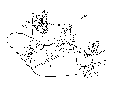
Fig. 1 is a schematic, pictorial illustration of a
catheter-based cardiac diagnostic system 20 comprising a
diagnostic balloon 40, in accordance with an embodiment of
the present invention. System 20 comprises a catheter 21,
wherein, as seen in an inset 25, a distal end of shaft 22
of the catheter is inserted through a sheath 23 into a
heart 26 of a patient 28 lying on a table 29. The proximal
end of catheter 21 is connected to a control console 24.
In the embodiment described herein, diagnostic balloon 40
carries diagnostic electrodes 50 for electrophysiological
diagnostic purposes, such as sensing arrhythmia activity
in tissue inside heart 26.
Physician 30 navigates the distal end of shaft 22 to
a target location in heart 26 by manipulating shaft 22
using a manipulator 32 near the proximal end of the catheter
and/or deflection from the sheath 23. During the insertion
of shaft 22, balloon 40 is maintained in a collapsed
configuration by sheath 23. By containing balloon 40 in a
collapsed configuration, sheath 23 also serves to minimize
vascular trauma along the way to target location.
To track positions of diagnostic electrodes 50, a
plurality of external electrodes 27 is coupled to the body
of patient 28; for example, three external electrodes 27
may be coupled to the patient's chest, and another three
external electrodes may be coupled to the patient's back.
(For ease of illustration, only one external electrode is
shown in Fig. 1.) In some embodiments, diagnostic
11
CA 3055656 2019-09-17
electrodes 50 sense potentials induced in heart 26 by
applying voltages between pairs of external electrodes 27.
Similar techniques used for tracking the locations of
diagnostic electrodes 50 inside heart 26, as described
above, is described in U.S. Patent Application 15/966,514,
filed April 30, 2018, entitled "Improved Active Voltage
Location (AVL) Resolution," which is assigned to the
assignee of the present patent application and whose
disclosure is incorporated herein by reference.
Based on the potentials sensed by electrodes 50 and
given the known positions of external electrodes 27 on the
patient's body, processor 41 calculates an estimated
location of at least a portion of electrodes 50 within the
patient's heart. Processor 41 may thus associate any given
signal received from diagnostic electrodes 50, such as an
electrophysiological signal, with the location at which the
signal was acquired.
Control console 24 comprises a processor 41, typically
a general-purpose computer, with suitable front end and
interface circuits 38 for receiving signals from catheter
21, as well as for applying treatment via catheter 21 in
heart 26 and for controlling the other components of system
20. Processor 41 typically comprises a general-purpose
computer with software programmed to carry out the
functions described herein. The software may be downloaded
to the computer in electronic form, over a network, for
example, or it may, alternatively or additionally, be
provided and/or stored on non-transitory tangible media,
such as magnetic, optical, or electronic memory.
In particular, processor 41 runs a dedicated algorithm
that enables processor 41 to perform the disclosed steps,
comprising calculations of the locations and respective
proximities.
12
CA 3055656 2019-09-17
The example configuration shown in Fig. 1 is chosen
purely for the sake of conceptual clarity. The disclosed
techniques may similarly be applied using other system
components and settings. For example, system 20 may
comprise other components and perform non-cardiac
diagnostics.
EXPANDABLE FRAME CARRYING DIAGNOSTIC AND FAR-FIELD
SENSING ELECTRODES
Figs. 2A and 2B are schematic pictorial illustrations
of an expandable frame 39 carrying diagnostic electrodes
50 and far-field sensing electrodes 55, in accordance with
embodiments of the present invention,.
As seen, an expandable frame 39 is coupled to a distal
end 65 of shaft 22, with expandable frame 39 extending
along a longitudinal axis 62 and comprising a plurality of
expandable spines 45 disposed about longitudinal axis 62
to define an internal lumen, such as one defined by a
surface of revolution about longitudinal axis 62, yet, in
general the internal lumen is not required to have
rotational symmetry. Distal end 65 of shaft 22 can slide
on a guidewire 60, as described below.
In some embodiments, at least an expandable spine from
among expandable spines 45 is made of flexible PCB. In an
embodiment, expandable spines 45 are all comprising
flexible PCB spines. Fig. 2A shows a plurality of
diagnostic electrodes 50 that is disposed over PCB spines
45 exterior. When catheter 40 is applied to acquire
diagnostic EP signals from tissue, electrodes 50 contact
both tissue and blood, and acquire both diagnostic near-
field signals and interfering far-field signals. A
respective plurality of far-field detecting directly
opposing electrodes 55 can be distinguished as facing an
13
CA 3055656 2019-09-17
internal volume defined by the surface of revolution about
longitudinal axis 62. Each reference electrodes 55 opposing
a respective diagnostic electrode 50 comes in contact only
with blood, and acquire only the respective interfering
far-field signals conducted by blood.
Inset 58 of Fig. 2A shows an example of a bio-
electrical signal 66 that an electrode 500 acquires when in
physical contact with cardiac tissue. Bio-electrical signal
66 comprises a diagnostic signal and an interfering signal,
as electrode 500 acquires at a same time both a near-field
diagnostic signal, and a far-field signal that is unrelated
to the EP activity at the contacted tissue. Reference
electrode 550, which is located opposite to diagnostic
electrode 500, at a very close proximity to electrode 500,
is electrically isolated from tissue and acquires only an
interfering far-field signal 68. Thus, simple subtraction
of signal 68 from signal 66 leaves just the tissue EP
signal.
In an embodiment, one or more leads to diagnostic
electrodes 50 include vias in the PCB stripes if spines 45,
for example, in order to minimize extra footprint and/or
electrical noises associated with the leads.
As noted above, the catheter shown in Fig. 2A further
comprises a hollow distal end 65 for frame 39 (e.g., a
movable edge of the catheter inside hollow shaft 22) to
slide on a guidewire 60 to access tissue in confined cardiac
regions such as that of an ostium of a pulmonary vein.
Distal end 65 can be retracted or pushed from a handle of
the catheter through hollow shaft 22 so as to expand or
collapse frame 39, respectively.
In an alternative embodiment, the far-field signal
acquiring electrode on the inside of each PCB 45 spine is
14
CA 3055656 2019-09-17
a single large electrode 155, as seen in Fig. 2B. As seen,
single reference electrode 155 is disposed over an entire
surface of the expandable spine. Such an alternative
embodiment may be desired if, for example, the far field
signal collected by small electrodes 55 is too noisy to be
useful. In an
embodiment, electrode 155 is formed by
electrically connecting the plurality of reference
electrodes 55 disposed on the spine with each other.
The illustration shown in Fig. 2B is chosen purely for
the sake of conceptual clarity. For example, in an
alternative embodiment, the inner side of each PCB
comprises several far-field detecting electrodes that are
each larger than an electrode 55 and smaller than an
electrode 155.
BALLOON CATHETER WITH DIAGNOSTIC ELECTRODES, FAR-FIELD
DETECTION ELECTRODES, AND GUIDEWIRE
Fig. 3 is a schematic pictorial illustration of
diagnostic balloon catheter 40 of Fig. 1, in accordance
with an embodiment of the present invention. As seen, in
the embodiments described by Fig. 3, balloon catheter 40
comprises a membrane 44 underlying expandable frame, such
as expandable frame 39 described above, that comprises
spines 45. Balloon 40 is fitted at the distal end of shaft
22. Inflatable balloon 40 has an exterior wall 43 of a bio-
compatible material, for example, formed from a plastic
such as polyethylene terephthalate (PET), polyurethane, or
PEBAe. Diagnostic electrodes 50 are disposed over an
exterior face of PCB strips 45 in circumference over
balloon 40.
At inset 51, the diagnostic electrodes 50 shown can
come in contact with both tissue and surrounding blood, and
hence, senses both near-field and far-field signals. The
CA 3055656 2019-09-17
shown reference electrode 55 is located on a surface of the
expandable frame directly opposite diagnostic electrode 50.
Reference electrode 55 is electrically isolated from
tissue, as described above. In an embodiment, the isolation
is done by partially encapsulating electrode 55 in an
insulating material, such as an epoxy resin or with another
polymer-based sealant. Insulation may also be provided, or
assisted, by using a water-resistant seal. Still, electrode
55 can only be in physical contact with surrounding blood
(and thus in electrical contact with blood), through gaps
57, and acquires far-field bio-electric signals than
propagate through blood from remote cardiac regions. As
noted above, such far-field interfering bio-electric
signals can therefore be subtracted from respective signals
acquired by diagnostic electrode 50 to achieve a quality
diagnostic signal.
As seen in Fig. 3, balloon 40 is fitted with a smooth,
round, and hollow distal end 65 for membrane 44 of balloon
40 to slide on a guidewire 60. The balloon is also
configured to have no protruding distal "knob," so that the
whole structure is smooth, so as to minimally perturb
tissue and blood flow. Thus, there is less chance of blood
clot formation. Even with the thin guidewire 60, there are
very few protuberances which may cause blood clots.
A balloon catheter having an internal distal end is
described in U.S. Provisional Patent Application 15/857101,
filed December 28, 2017, entitled "Balloon Catheter with
Internal Distal End," which is assigned to the assignee of
the present patent application and whose disclosure is
incorporated herein by reference.
Fig. 4 is a pictorial volume rendering of diagnostic
balloon 40 of Fig. 3, in accordance with an embodiment of
the present invention. As seen in Fig. 4, the balloon is
16
CA 3055656 2019-09-17
configured to be held distally by an internal flexible
structure comprising distal end 65, so there is no need for
a protruding distal end to fix the balloon to shaft 22,
thereby keeping the whole structure smooth, and therefore
minimally perturb tissue and blood flow. The balloon has a
soft round distal end and can slide on guidewire 60. To
allow for the sliding of balloon 40, hollow distal end 65
is designed to be moved on guidewire 60 either when the
balloon is in a deflated form or when the balloon is in an
inflated form.
In some embodiments, electrodes 50 are interconnected
to create an intracardiac bi-polar electrode configuration.
In another embodiment the electrodes sense signals relative
to an external reference electrode, such as one of
electrodes 27 attached to the skin.
As further seen in Fig. 4, opposing electrodes 55 can
be distinguished as facing the balloon wall (the balloon
wall and any sealant or adhesive are illustrated as
transparent only to show electrodes 55).
The illustration shown in Fig. 4 is chosen purely for
the sake of conceptual clarity. Fig. 4 shows only portions
relevant to embodiments of the present invention. Other
system elements, such as electrical wiring for the PCB,
temperature sensors, and sealing elements, if required, are
omitted.
Fig. 5 is a flow chart that schematically illustrates
a method for canceling interference per electrode pairs
disposed over the diagnostic balloon of Fig. 3, in
accordance with an embodiment of the present invention. The
process begins with a diagnostic electrode, such as
electrode 50, sensing diagnostic signals, at a diagnostic
signals sensing step 70. In parallel, reference electrode
55 disposed opposing diagnostic electrode 50, senses
17
CA 3055656 2019-09-17
interfering signals, at an interference sensing step 72.
Next, processor 41 receives the diagnostic signals sensed
by diagnostic electrode 50, and the interfering signals
sensed by reference electrode 55, at a signal receiving
step 74. Finally, processor 41 calculates, using the
dedicated algorithm, corrected diagnostic signals by
subtracting the interfering signals from the diagnostic
signals, at a signal calculation step 76.
The example flow chart shown in Fig. 5 is chosen purely
for the sake of conceptual clarity. Additional steps may
be included, which are omitted for simplicity of
presentation. For example, in an additional embodiment, the
sensed signals are filtered prior to being received by
processor 41.
It will be appreciated that the embodiments described
above are cited by way of example, and that the present
invention is not limited to what has been particularly
shown and described hereinabove. Rather, the scope of the
present invention includes both combinations and sub-
combinations of the various features described hereinabove,
as well as variations and modifications thereof which would
occur to persons skilled in the art upon reading the
foregoing description and which are not disclosed in the
prior art. Documents incorporated by reference in the
present patent application are to be considered an integral
part of the application except that to the extent any terms
are defined in these incorporated documents in a manner
that conflicts with the definitions made explicitly or
implicitly in the present specification, only the
definitions in the present specification should be
considered.
18
CA 3055656 2019-09-17