Note : Les descriptions sont présentées dans la langue officielle dans laquelle elles ont été soumises.
CA 03057267 2019-09-19
WO 2018/203247
PCT/IB2018/053035
Improved dental implant system
Field of the Invention
The present invention relates in general to a dental implant with an improved
coupling for
an insertion tool and/or for a secondary part and/or any other superimposed
element, such
as, for instance, an abutment, superimposed on the dental implant. The present
invention
also relates to a secondary part, such as, for instance, an abutment, with an
improved
coupling to a dental implant. Moreover, the present invention also relates to
an insertion
tool with an improved coupling to a dental implant. In addition, the present
invention also
relates to a dental implant system, in particular a multi-part dental implant
system with an
improved coupling between a dental implant and a secondary part, such as, for
instance, an
abutment, wherein the coupling is also suitable for cooperating with an
insertion tool
intended to place the dental implant in a receiving bone.
Background of the Invention
Generally, multi-part dental implant systems are used in dental surgery to
reconstruct dental
parts of a human being. Usually, a multi-part implant system is comprised of a
dental
implant, preferably a dental screw, which is inserted by screwing or pressing
into a receiving
bore which has been prepared e.g. in the bone tissue, and of an abutment or a
secondary
part which can be attached to an internal blind bore of the dental implant.
The abutment or
secondary part is adapted, inter alia, to support a dental prosthesis or a
dental bridge. The
attachment of the abutment or of the secondary part to the dental implant is
achieved by
means of a connection screw which is threadingly fixed to an internal thread
of the internal
blind bore of the dental implant.
A dental implant system including a dental implant, in particular a dental
implant screw, a
secondary part (namely an abutment) and a connection screw are known from US
2005/0287497 Al. The internal blind bore of the known dental implant includes
a stabilizing
section which extends from a coronal end of the dental implant, a drive and
indexing section
which extends apically from the apical end of the stabilizing section and an
internal threaded
section extending apically from the apical end of the drive and indexing
section. The known
drive and indexing section is formed of a plurality of alternating equally
dimensioned lobes
with concave sections interposed between convex sections, such that a flower-
like
configuration is implemented. The abutment of the known dental implant system
of US
1
CA 03057267 2019-09-19
WO 2018/203247
PCT/IB2018/053035
2005/0287497 Al is shaped at its apical end in a manner which is complementary
to the
stabilizing section and to the drive and indexing section of the dental
implant and further has
a through bore allowing the connection screw to pass therethrough for engaging
the internal
threaded section of the blind bore of the dental implant and holding the
abutment fixed in a
.. determined angular position on the dental implant.
A frequent problem arising with the above-described multi-part dental implant
systems is
the difficulty of correct angular positioning and stability of the abutment or
of the secondary
part within the dental implant which has already been placed in the bone
tissue. Further, as
the same coupling means are used to position the secondary part on the dental
implant and
to couple the same to an insertion instrument which is used to place the
dental implant in
the bone tissue, the problem of sufficient torque resistance of the coupling
means arises. Yet
another problem arising in multi-part dental implant systems is the sealing
between the
dental implant and the secondary part, as for the sake of sterility, the
penetration of fluid
into the internal blind bore of the dental implant via the coupling means
should be
minimized.
In US 2005/0287497 Al the problem of correct angular positioning of the
secondary part on
the dental implant was addressed by devising an internal connection of the
dental implant
and the secondary part (namely an abutment) in which the dental implant
includes the
above-mentioned lobed configuration for installing the secondary part and a
beveled surface
positioned on the proximal side of the lobed configuration for providing
stability between
the dental implant and the corresponding secondary part.
Nevertheless, there is still the necessity in the art of dentistry to provide
for a dental
implant, a secondary part, an insertion tool and a dental implant system
including a dental
implant and a secondary part, wherein the above-mentioned positioning and
stability
problems along with the torsional strength and sealing problems are solved in
a satisfactory
manner.
Summary of the Invention
The aim of the present invention is to provide an improved dental implant, an
improved
secondary part, an improved insertion tool and an improved dental implant
system including
a dental implant and a secondary part which avoids the drawbacks of the prior
art devices,
and thus allows a stable and sterile coupling between the dental implant and
the secondary
2
CA 03057267 2019-09-19
WO 2018/203247
PCT/IB2018/053035
part in a plurality of angular positions, while at the same time the
mechanical strength and
the torsional resistance of the coupling between the dental implant and the
secondary part
and/or the insertion tool are increased as compared to the conventional prior
art solutions.
Within the scope of this aim, an object of the present invention is to provide
an improved
dental implant, an improved secondary part, an improved insertion tool and an
improved
dental implant system including a dental implant which can be used in a
plurality of dental
applications for supporting various superstructures.
Further, within the scope of the above aims, another object of the present
invention is to
provide an improved dental implant, an improved secondary part, an improved
insertion
tool and an improved dental implant system including a dental implant which
can be
manufactured easily, thus reducing the overall costs for the production of the
dental implant
system as a whole and of its individual components.
Yet another object of the present invention is to provide an improved coupling
for a multi-
part dental implant system, wherein the number of parts is minimized.
This aim, these objects and others which will become more apparent from the
description
given hereinafter are achieved by a dental implant as defined in claim 1, a
secondary part for
a dental implant as defined in claim 24, an insertion tool as defined in claim
35 and a dental
implant system as defined in claims 45 and 46.
Further advantageous aspects of the present invention are defined in the
appended
dependent claims.
The present invention provides in certain embodiments thereof for a dental
implant for use
in a dental implant system including a secondary part, wherein the dental
implant has a
substantially cylindrical shape with a longitudinal axis defining a
longitudinal direction, the
dental implant including: a coronal section including a coronal end of the
dental implant; a
threaded region extending apically from the coronal section to an apical tip
of the dental
implant; and an internal blind bore for connection to the secondary part, the
internal blind
bore including: a stabilizing section which extends apically from the coronal
end of the
dental implant; and a drive and indexing section which extends apically from
an apical end of
the stabilizing section, wherein the drive and indexing section is provided
with a plurality of
3
CA 03057267 2019-09-19
WO 2018/203247
PCT/IB2018/053035
connecting lobes having a concave shape and extending in the longitudinal
direction, the
connecting lobes being interconnected by respective lobe linking areas also
extending in the
longitudinal direction, each of the lobe linking areas including: two convex
sections
extending in the longitudinal direction and adjacent to a respective
connecting lobe; and a
concave section extending in the longitudinal direction between the two convex
sections.
Preferably, the internal blind bore of the dental implant further includes an
apical internally
threaded section extending apically from an apical end of the drive and
indexing section
thereof.
Further preferably, in the dental implant according to the present invention,
both the
connecting lobes and the lobe linking area extend substantially along the
entire axial
extension of the drive and indexing section.
Alternatively, each lobe linking area may include an apical portion which has
a step-like
configuration.
Further preferably, the apical portion of lobe linking area has a lateral
surface which is part
of a lateral cylinder surface having an axis that is coincident with the axis
of the dental
.. implant, wherein the lateral surface is provided with a ledge which extends
in a radial
direction towards the axis of the dental implant. In a further alternative,
the apical portion
may have a lateral surface which is part of a truncated cone surface flaring
out coronally and
having an axis that is coincident with the axis of the dental implant, wherein
the lateral
surface is provided with a ledge which extends in a radial direction towards
the axis of the
dental implant. The radial extension of the ledge may be substantially
perpendicular to the
axis of the dental implant or may be apically inclined with respect to the
axis of the dental
implant.
According to yet another preferred embodiment of the dental implant of the
present
invention the connecting lobes are parts of respective cylinders with a
lateral area that is
parallel to the axis of the dental implant, and wherein preferably the
cylinder parts are half-
cylinders. Further, the convex and concave sections of the lobe linking areas
may also be
parts of respective cylinders with a lateral area that is parallel to the axis
of the dental
implant.
4
CA 03057267 2019-09-19
WO 2018/203247
PCT/IB2018/053035
Furthermore, advantageously, the dental implant includes a substantially
circular platform at
the coronal end of the drive and indexing section which is adjacent to the
apical end of the
stabilizing section. The substantially circular platform may be formed by the
radially
protruding coronal parts of the lobe linking areas.
According to an additional advantageous aspect of the dental implant according
to the
present invention, the drive and indexing region thereof is formed by six
connecting lobes
and an equal number of the lobe linking areas which are interposed between the
connecting
lobes.
In the above dental implant, it is particularly advantageous if the
stabilizing section is shaped
as a truncated cone flaring out in a coronal direction and with a coronal
opening having an
angle of 5 degrees to 7.9 degrees, more preferably of 5 degrees to 7.7
degrees, even more
preferably of 5 degrees to 7 degrees and most preferably 7 degrees with
respect to the axis
of the dental implant. All foregoing ranges are understood as including the
boundary values
and furthermore all foregoing values are understood to include deviations from
the exact
value within the engineering tolerances known to the person skilled in the
art. Same applies
for all values, ranges of values and ratios indicated in the following
description and claims in
respect to any feature of the present application.
In the above dental implant the coronal section may preferably include a
smooth section
extending in the apical direction from the coronal end of the dental implant
and a threaded
section extending in the apical direction from the apical end of the smooth
section up to the
coronal end of the threaded region, the threaded section being adapted for
securing a
secondary part to an external part of the dental implant and/or the threaded
section
including a reverse thread and/or the threaded section being adapted to
facilitate
osseointegration of the dental implant in a bone tissue.
The smooth section of the coronal section of the dental implant may preferably
comprise a
beveled part in the vicinity of the coronal end of the coronal section of the
dental implant,
wherein the beveled part is apically inclined at its periphery. It is
particularly advantageous if
the beveled part forms an angle of 17 to 27 degrees, more preferably an angle
of 20 to 24
degrees and most preferably an angle of 22.5 degrees with respect to a plane
that is
perpendicular to the axis of the dental implant.
5
CA 03057267 2019-09-19
WO 2018/203247
PCT/IB2018/053035
The coronal end of the dental implant may be defined by an optional flat
shoulder which is
adjacent to the beveled part, wherein the flat shoulder lies preferably on the
plane which is
perpendicular to the axis of the dental implant, wherein further preferably
along a radius
extending from the axis of the dental implant the ratios of the radial width
of the flat
shoulder to the radial width of the projection of the beveled part on the
radius are from 1/5
to 1/3. Otherwise if the flat shoulder is omitted, the beveled part defines
the coronal end of
the dental implant.
According to a further preferred advantageous aspect of the invention an
undercut is
provided at the apical end of the drive and indexing section and more
preferably between
the apical end of the drive and indexing section and a coronal platform of the
apical
internally threaded section. Preferably the undercut extends apically below
the ledges of the
apical portion of the lobe linking areas up to a coronal platform of the
apical internally
threaded section of the internal blind bore of the dental implant. The coronal
platform may
extend on a plane that is perpendicular to the axis of the dental implant.
Furthermore,
preferably, the undercut has a reduced extension at the connecting lobes of
the drive and
indexing section of the dental implant or it can also be omitted at the
connecting lobes, such
that the undercut will have roughly a petal-like configuration.
In the above dental implant the threaded region may advantageously include at
least one
flute, each flute being preferably configured to mill bone, collect bone,
condense bone and
disperse bone when the dental implant is rotated both in the clockwise and in
the
counterclockwise direction. Further preferably, the thread of the threaded
region (14) of the
dental implant may have a helical shape.
In other embodiments the present invention provides for a secondary part for
use in a
dental implant or a dental implant system including a dental implant, the
secondary part
having a central bore extending along a longitudinal axis thereof, the
longitudinal axis
defining a longitudinal direction, the secondary part including: a coronal
section including a
coronal end of the secondary part; a stabilizing section extending apically
from an apical end
of the coronal section, where preferably at least at an apical part thereof is
generally shaped
as a truncated cone flaring out in a coronal direction of the secondary part;
and an indexing
section extending apically from an apical end of the stabilizing section,
wherein the indexing
section is provided with a plurality of connecting lobes extending in the
longitudinal
direction and having a convex shape, the connecting lobes being interconnected
by
respective lobe linking areas also extending in the longitudinal direction,
each of the lobe
linking areas including two concave sections extending in the longitudinal
direction and
6
CA 03057267 2019-09-19
WO 2018/203247
PCT/IB2018/053035
adjacent to a respective connecting lobe; and a convex section extending in
the longitudinal
direction between the two convex sections.
Preferably, the secondary part is embodied as an abutment for supporting a
single tooth or a
.. dental bridge.
Preferably, in the above-mentioned secondary part both the connecting lobes
and the lobe
linking areas of the indexing section extend substantially along the entire
axial extension of
the indexing section.
Further, preferably, in the secondary part the connecting lobes are parts of
respective
cylinders with a lateral area that is parallel to the axis of the secondary
part, and the cylinder
parts are further preferably half-cylinders.
Also preferably the concave and convex sections of the lobe linking areas are
parts of
respective cylinders with a lateral area that is parallel to the axis of the
secondary part.
Advantageously, the number of connecting lobes and the number of lobe linking
areas of the
indexing section of the secondary part are equal to six.
According to an advantageous aspect of the above-described secondary part the
apical part
of the stabilizing section is shaped as a truncated cone flaring out in a
coronal direction and
with a coronal opening having an angle of 5 degrees to 7.9 degrees, more
preferably of 5
degrees to 7.7 degrees, even more preferably of 5 degrees to 7 degrees and
most preferably
7 degrees with respect to the axis of the secondary part.
The stabilizing section may further advantageously include a coronal part
which has a larger
outward flaring region in comparison to the outward flaring region of the
apical part of the
stabilizing section, such as to allow the formation of the supporting ledge at
the apical end of
the coronal section of the secondary part.
7
CA 03057267 2019-09-19
WO 2018/203247
PCT/IB2018/053035
Furthermore, according to an optional aspect, the coronal section of the above-
mentioned
secondary part further includes means for rotationally positioning a dental
prosthesis
thereon, wherein the prosthesis may include a single tooth or a dental bridge.
According to a further advantageous aspect of the above-mentioned secondary
part the
interface between the coronal part of the stabilizing section and the apical
part of the
stabilizing section is formed as a beveled surface, wherein the beveled
surface is apically
inclined towards its periphery. The beveled surface may form an angle of 17 to
27 degrees,
more preferably an angle of 20 to 24 degrees and most preferably an angle of
22.5 degrees
with respect to a plane that is perpendicular to the axis A of the secondary
part.
In further embodiments the present invention provides for an insertion tool
for use in a
dental implant or a dental implant system including a dental implant, wherein
the insertion
tool has a longitudinal axis defining a longitudinal direction, the insertion
tool including a
coronal section having a shank portion for connection to a rotary device; and
an apical
section for engagement with an internal bore of the dental implant, wherein
the apical
section includes from coronal to apical a first stabilizing section and a
drive section, and
wherein the drive section is provided with a plurality of connecting lobes
having a convex
shape and extending in the longitudinal direction, the connecting lobes being
interconnected
by respective lobe linking areas also extending in the longitudinal direction,
each of the lobe
linking areas being substantially of concave shape.
Preferably, the lobe linking areas of the drive section of the insertion tool
include two
concave sections extending in the longitudinal direction and adjacent to a
respective
connecting lobe thereof; and a convex section extending in the longitudinal
direction
between the two convex sections.
Also preferably, in the above-mentioned insertion tool both the connecting
lobes and the
lobe linking area of the drive section extend substantially along the entire
axial extension of
the drive section.
The connecting lobes of the drive section of the foregoing insertion tool are
parts of
respective cylinders with a lateral area that is parallel to the axis of the
insertion tool, and
wherein preferably the cylinder parts are half-cylinders.
8
CA 03057267 2019-09-19
WO 2018/203247
PCT/IB2018/053035
Furthermore, preferably the lobe linking areas of the drive section of the
foregoing insertion
tool are parts of respective cylinders with a lateral area that is parallel to
the axis of the
insertion tool, wherein further preferably the cylinder parts are half-
cylinders.
Alternatively, when the lobe linking areas of the drive section of the
insertion tool include
two concave sections extending in the longitudinal direction and adjacent to a
respective
connecting lobe thereof; and a convex section extending in the longitudinal
direction
between the two convex sections, the concave and convex sections of the lobe
linking areas
are parts of respective cylinders with a lateral area that is parallel to the
axis of the insertion
tool.
The number of connecting lobes and the number of lobe linking areas of the
drive section of
the above-mentioned insertion tool are preferably equal to six.
In the above-mentioned insertion tool the first stabilizing section may be
shaped generally as
a truncated cone flaring out coronally, and further preferably a coronal
opening of the first
stabilizing section has an angle of 5 degrees to 7.9 degrees, more preferably
of 5 degrees to
7.7 degrees, even more preferably of 5 degrees to 7 degrees and most
preferably 7 degrees
with respect to the axis of the insertion tool.
The insertion tool may further include a circular recess which is formed
peripherally around
the axis of the insertion tool, the circular recess dividing the drive section
into a coronal part
and an apical part, the circular recess being adapted to house a resilient 0-
ring or a split C-
ring.
In a preferred embodiment the above-described insertion tool includes a second
stabilizing
section arranged at an apical end of the drive section and defining the apical
end of the
insertion tool, wherein the second stabilizing section has preferably a
cylindrical shape
dimensioned to match an internal threaded section of the blind bore of the
dental implant.
Furthermore, the coronal section of the above-described dental implant may
include in a
coronal region thereof an engagement element configured to engage a rotary
machine
and/or the coronal section of the insertion tool may include in an apical
region thereof a
manual tool engagement section configured to engage a manual torque applying
tool,
wherein preferably the manual tool engagement section is hexagonal along an
axial cross
9
CA 03057267 2019-09-19
WO 2018/203247
PCT/IB2018/053035
section of the insertion tool with each side of the hexagon including a
plurality of recesses,
preferably of a substantially conical configuration.
In yet other embodiments a dental implant system is provided, wherein the
dental implant
system includes a dental implant and a secondary part as set forth
hereinabove. Preferably,
the dental implant system further includes an attachment tool as described
hereinabove.
The dental system may also further include a healing cap, an impression cap
and a
threadable secondary part which can be threaded externally to the dental
implant without
the need for a fixation screw extending through the internal blind bore of the
dental
implant.
Preferably, the threadable secondary part includes an internal thread in a
section thereof of
an axially symmetric shape, such that the threadable secondary part is
threadable to the
externally threaded section of the coronal section of the dental implant. The
threadable
secondary part may further include an internal beveled surface having an
inclination angle of
17 to 27 degrees, more preferably an angle of 20 to 24 degrees and most
preferably an angle
of 22.5 degrees with respect to a plane that is perpendicular to a
longitudinal axis of the
threadable secondary part. Further the threadable secondary part may have the
overall
shape of an axially symmetric rotation body including a coronal cylindrical
section, a beveled
truncated cone-shaped section and an apical cylindrical section, wherein
preferably the
coronal cylindrical section of the threadable secondary part is smaller in
diameter than the
apical cylindrical section of the threadable secondary part and the beveled
truncated cone-
shaped section forms therebetween an apposition surface for a superstructure,
wherein
further preferably the beveled truncated cone-shaped section forms an angle of
17 to 27
degrees, more preferably an angle of 20 to 24 degrees and most preferably an
angle of 22.5
degrees with respect to a plane that is perpendicular to the axis of the
secondary part.
Preferably, the healing cap is shaped as a rotationally symmetrical rotation
body along a
longitudinal axis thereof, the healing cap having an enlarged head arranged at
the coronal
end thereof, wherein the enlarged head is provided with wrench engaging means,
the
enlarged head of the healing cap being followed further apically by a
stabilizing section
which matches exactly the stabilizing section of the dental implant.
The healing cap may optionally further include apically from the stabilizing
section an
intermediate section and a threaded section which is adapted to threadingly
engage the
CA 03057267 2019-09-19
WO 2018/203247
PCT/IB2018/053035
internal thread of the apical internally threaded section of the internal
blind bore of the
dental implant.
According to a further preferred alternative the healing cap includes further
apically from
the stabilizing section an additional section that follows the outline of the
drive and indexing
section of the dental implant.
Further in all embodiments the healing cap may advantageously include an
internal beveled
surface which exactly follows the shape of the beveled part of the smooth
section of the
coronal section of the dental implant, such that the internal beveled surface
of the healing
cap has an angle of 17 to 27 degrees, more preferably an angle of 20 to 24
degrees and most
preferably an angle of 22.5 degrees with respect to a plane that is
perpendicular to the
longitudinal axis of the healing cap.
Brief Description of the Drawings
Further characteristics and advantages of the present invention will become
more apparent
from the following description of a preferred but not exclusive embodiment of
the implant
system according to the invention, illustrated by way of non-limitative
example in the
accompanying drawings, wherein:
Fig. 1 is a side view of a dental implant incorporating a coupling for a
secondary part,
wherein the coupling is devised according to the present invention;
Fig. 2 is a broken cross-sectional perspective view of the dental implant of
Fig. 1;
Fig. 2A is an enlarged presentation of a section of the broken cross-sectional
perspective view of the dental implant of Fig. 2;
Fig. 3 is a top view of the dental implant of Fig. 1;
Fig. 3A is an enlarged detail of the top view of the dental implant according
to Fig. 3;
Fig. 3B is a variation of the enlarged detail of Fig. 3A;
Fig. 4 is a partially sectional
view of the dental implant of Fig. 1;
Fig. 5A is a side view of the dental implant of Figs. 1 through 4 with the
secondary
part mounted thereon;
Fig. 5B is a cross-sectional view of the dental implant of Figs. 1 through 4
with a
secondary part mounted thereon;
11
CA 03057267 2019-09-19
WO 2018/203247
PCT/IB2018/053035
Fig. 5C is an enlarged detail view of Fig. 5B;
Fig. 5D is a perspective view of the dental implant with the secondary part of
Fig. 5A
fixed thereon by means of a connection screw;
Fig. 5E is a broken cross-sectional perspective view of the dental implant of
Fig. 5A
with the secondary part mounted thereon by means of a connection screw;
Fig. 6A is a perspective view of the secondary part according to the present
invention
adapted to be received in the dental implant shown in Figs. 1 through 5E;
Fig. 6B is a bottom view of the secondary part according to the present
invention
adapted to be received in the dental implant shown in Figs. 1 through 5E;
Fig. 7A is a side view of a dental implant which is variated as compared to
the dental
implant of Figs. 1 through 4 with a secondary part mounted thereon which is
also different
from the secondary part of Figs. 5A through 5E;
Fig. 7B is a cross-sectional view of the dental implant of Fig. 7A with the
secondary
part mounted thereon;
Fig. 7C is a perspective view of the dental implant of Fig.7A with the
secondary part
threadingly fixed thereon by means of a connection screw;
Fig. 7D is a broken cross-sectional perspective view of the dental implant of
Fig. 7A
with the secondary part mounted thereon by means of a connection screw;
Fig. 7E is a perspective view of the secondary part of Figs. 7A through 7D;
Fig. 8A is a side view of the dental implant of Figs. 1 through 4 with an
insertion tool
mounted thereon;
Fig. 8B is a cross-sectional view of the dental implant of Fig. 8A with an
insertion tool
mounted thereon;
Fig. 8C is a broken cross-sectional perspective view of the dental implant of
Fig. 8A
with the insertion tool mounted thereon;
Fig. 8D is a perspective view of the dental implant of Fig. 8A with the
insertion tool
mounted thereon;
Fig. 9 is a perspective view of an insertion tool according to the present
invention
adapted to be received in the dental implant according to the present
invention as described
in the above figures;
Fig. 10A is a side view of the dental implant of Figs. 1 through 4 with a
further
different secondary part mounted thereon;
12
CA 03057267 2019-09-19
WO 2018/203247
PCT/IB2018/053035
Fig. 10B is a partially sectional view of the dental implant of Fig. 10A with
the further
different secondary part mounted thereon;
Fig. 10C is a broken cross-sectional perspective view of the dental implant of
Fig. 10A
with the further different secondary part mounted thereon;
Fig. 11A is a side view of the dental implant of Figs. 1 through 4 with a
healing cap
mounted thereon;
Fig. 11B is a cross-sectional view of the dental implant of Fig. 11A with the
healing
cap mounted thereon; and
Fig. 11C is a broken cross-sectional perspective view of the dental implant of
Fig. 11A
with the healing cap mounted thereon.
Detailed Description of the Invention
Whenever reference is made in the present specification to connecting lobes or
to linking
areas as having a concave or a convex shape, such concavity or convexity is
understood as
referring to a transverse cross section of a dental implant, a secondary part,
an insertion
tool, a healing cap along a plane that is perpendicular to a longitudinal axis
of the listed
dental items.
With reference to the enclosed Fig. 1 reference numeral 1 designates a dental
implant, in
particular a dental implant screw, having a coronal section 11 and a threaded
region 14
extending apically from the coronal section 11 to an apical tip 15 of the
dental implant 1. The
corona! section 11 includes at an external part thereof a smooth section 12
extending in the
apical direction from the coronal end of the dental implant land a threaded
section 13
extending in the apical direction from the apical end of the smooth section 12
up to a
coronal end of the threaded region 14. The dental implant 1 has a
substantially cylindrical
shape with a longitudinal axis A as indicated, for instance, in Fig. 1.
The threaded section 13 of the coronal section 11 of the dental implant 1,
which is an
optional feature of the dental implant 1, may be provided to improve bone
retention and
osseointegration, for example in the form of micro-threads. Optionally the
threaded section
13 of the corona! section 11 may be configured to have a double lead, with
preferably a
pitch of 0.5 mm and a thread angle of 25 degrees to 45 degrees and more
preferably from
25 degrees to 35 and most preferably 25 degrees. Optionally the threaded
section 13 of the
corona! section 11 may be configured according to the configuration of the
threaded section
13
CA 03057267 2019-09-19
WO 2018/203247
PCT/IB2018/053035
14 of the dental implant 1 and/or it may be configured to facilitate
osseointegration of the
dental implant 1 within the bone. Optionally the threaded section 13 of the
corona! section
11 of the dental implant 1 may be configured according to at least one or more
threading
parameters as known in the art, for example including, but not limited to
lead, pitch, thread
angle, thickness, major diameter, minor diameter, taper angle, thread
orientation, end
position, starting position, porosity, number of stops, number of starts,
number of leads,
number of cuts, lead-in angle or the like or any combination thereof of
threading variables
and/or parameters.
Yet according to another preferred alternative, the threaded section 13 of the
corona!
section 11 of the dental implant 1 may be embodied as a reverse thread on the
external part
of the dental implant 1 for facilitating removal of the dental implant 1 from
the bone into
which it has been inserted. Such removal of the dental implant can be
performed by means
of an instrument that is well-known to the person skilled in the art.
Furthermore, the threaded section 13 of the corona! section 11 of the dental
implant 1 along
with the flutes describes hereinbelow may be of the self-drilling, self-
tapping, self-collection
bone and bone condensing type as disclosed in detail in the International
Patent Application
WO 2015/118543 Al in the name of Fromovich, the respective content thereof
being
herewith incorporated by reference. Thus, the threaded section and the flutes
of this
invention provide for a dynamic action during the bone insertion. The implant
according to
latter embodiments may be utilized at a heal site following bone growth or it
may be utilized
at an extraction site.
Yet according to another preferred alternative, the threaded section 13 of the
corona!
section 11 of the dental implant 1 may be embodied as a thread for securing a
secondary
part which is fixed to the external part of the dental implant 1. In the
context of the present
invention a secondary part is intended to designate any superstructure which
can be placed
on a dental implant such as, for instance, a dental abutment adapted for
supporting a single
tooth including a dental crown or for supporting a dental bridge. For better
comprehension
in this description the generic term "secondary part" will be used, unless the
"secondary
part" is intended to designate a specific element such as, for instance, an
abutment adapted
for supporting a single tooth including a dental crown or for supporting a
dental bridge or for
holding a healing cap or an impression cap.
The smooth section 12 of the coronal section 11 of the dental implant 1 may
further
optionally comprise a beveled part 121 in the vicinity of the coronal end
thereof. In this way
the smooth section 12 of the coronal section 11 of the dental implant 1 will
have generally
from coronal to apical a truncated cone outline followed by a cylindrical
outline. The beveled
14
CA 03057267 2019-09-19
WO 2018/203247
PCT/IB2018/053035
part 121 advantageously provides for a more stable connection to a
superimposed
secondary part. Further, the beveled part 121 may also advantageously provide
for a better
sealing with the superimposed secondary part, as will be explained
hereinbelow.
.. Preferably, the beveled part 121 forms an angle of 17 to 27 degrees, more
preferably an
angle of 20 to 24 degrees and most preferably an angle of 22.5 degrees with
respect to a
plane that is perpendicular to the axis A of the dental implant 1. The latter
most preferred
inclination angle of the beveled part 121 is particularly advantageous in
terms of mechanical
stability and sealing when the dental implant is connected to a superimposed
secondary part
which may be embodied, for instance, as an abutment adapted for supporting a
single tooth
or for supporting a dental bridge.
The coronal end of the dental implant 1 is preferably defined by a flat
shoulder 122 which is
adjacent to the beveled part 121. The flat shoulder 122 lies preferably on the
plane which is
perpendicular to the axis A of the dental implant 1. Further, the flat
shoulder 122 is
preferably relatively narrow as compared to the beveled part 121. Along a
radius extending
from the axis A of the dental implant 1 preferred ratios of the radial width
of the flat
shoulder 122 to the radial width of the projection of the beveled part 121 on
the radius are
from 1/5 to 1/3.
The flat shoulder 122 also provides advantageously, in conjunction with the
beveled part
121, for a centering platform for a secondary part that is superimposed on the
dental
implant. Such superimposed secondary part may comprise, as mentioned above, an
abutment adapted for supporting a single tooth including a dental crown or for
supporting a
dental bridge.
According to a further preferred option, the smooth section 12 extending below
the beveled
part 121 may be optionally machined and acid etched and/or provided with micro
grooves
so as to improve the osseointegration of the dental implant 1.
The threaded region 14 of the dental implant 1 is preferably fitted with at
least two flutes
141 disposed along its full length. As disclosed in detail in the
International Patent
Application WO 2015/118543 Al in the name of Fromovich, who is also the
inventor of the
present invention, the flutes 141 are preferably configured to mill bone,
collect bone,
condense bone and disperse bone when the dental implant 1 is rotated with a
dental
implant maneuvering tool, for example in the form of a dental hand-piece, both
in the
CA 03057267 2019-09-19
WO 2018/203247
PCT/IB2018/053035
clockwise and in the counterclockwise direction. The thread of the threaded
region 14 of the
dental implant 1 is designated with reference numeral 142 and preferably has a
helical
shape.
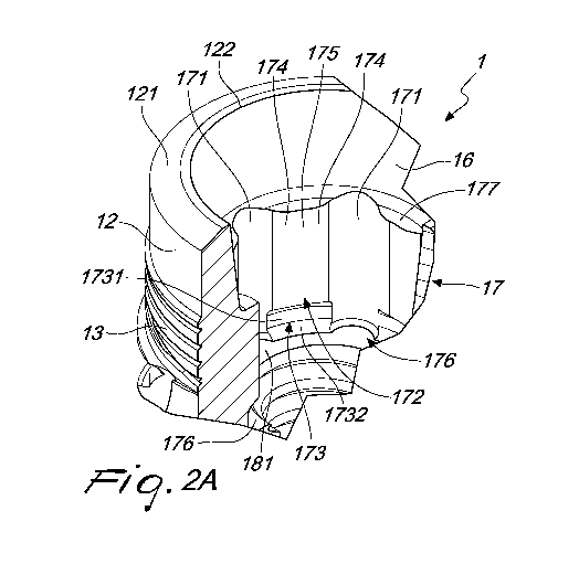
Figures 2 and 2A show an internal blind bore of the dental implant 1 including
a stabilizing
section 16 which extends apically from the coronal end of the dental implant
1, said coronal
end being defined by the shoulder 122, if present, or by the beveled part 121,
a drive and
indexing section 17 which extends apically from the apical end of the
stabilizing section 16
and an apical internally threaded section 18 extending apically from the
apical end of the
drive and indexing section 17.
The stabilizing section 16 extends from the shoulder 122 defining the coronal
end of the
dental implant 1 in an apical direction or from the beveled part 121 if the
shoulder 122 is
omitted. The shoulder 122 is, as explained, preferably substantially flat and
lies on a plane
which is perpendicular to the axis A of the dental implant 1. Nevertheless,
according to a
variation of the embodiment shown in Figs. 2 and 2A the shoulder 122 may have
an
inclination with respect to the plane which is perpendicular to the axis A of
the dental
implant 1 so as to match the shape of the secondary part (for instance an
abutment) placed
over the dental implant 1. The shoulder 122 further extends preferably around
the whole
blind bore of the dental implant 1 and has a constant width around the same.
The stabilizing section 16 of the present invention is intended to provide for
a highly stable
connection between the dental implant and the secondary part. At the same the
stabilizing
section 16 is intended to provide for good sealing with a complementarily
shaped section of
the secondary part which is received in the internal blind bore of the dental
implant 1. In
addition, the stabilizing section 16 provides for a self-locking function with
the
complementarily shaped section of the secondary part when the secondary part
is inserted
into the internal blind bore of the dental implant 1.
With reference to Fig. 4 the stabilizing section 16 is shaped as a truncated
cone flaring out in
a coronal direction and having a coronal opening with an angle of 5 degrees to
7.9 degrees,
more preferably of 5 degrees to 7.7 degrees, even more preferably of 5 degrees
to 7 degrees
and most preferably 7 degrees with respect to the axis A of the dental implant
1. The
inventor of the present application has found that the above opening range of
the stabilizing
section 16 in general and the preferred value of 7 degrees in particular
provide for a highly
stable connection between the dental implant and the secondary part combined
with an
16
CA 03057267 2019-09-19
WO 2018/203247
PCT/IB2018/053035
optimal sealing between the dental implant and the secondary part as well as
an optimal
self-locking effect of the secondary part in the internal blind bore of the
dental implant.
With further reference to Figs. 2, 2A, 3, 3A, 3B and 4 the drive and indexing
section 17 of the
dental implant 1 will be described in more detail.
In particular, according to the present invention, the drive and indexing
section 17 of the
dental implant 1 is provided with a plurality of connecting lobes 171 having a
concave shape
extending substantially along the entire axial extension of the drive and
indexing section 17.
Preferably, the connecting lobes 171 are parts of respective cylinders with a
lateral area that
is parallel to the axis A of the dental implant 1. Further, preferably, the
cylinder parts
defining the connecting lobes 171 may be embodied as half-cylinders.
In the particular embodiment shown in Figs. 2, 2A, 3, 3A, 3B and 4 the number
of connecting
lobes 171 is equal to six, but the person skilled in the art will appreciate
that the number of
connecting lobes 171 can be varied according to the number of indexing
positions of the
secondary part on the dental implant and also for providing a sufficient
torque coupling to
rotate and thus install the dental implant in a jaw bone of a patient and
further to also
remove the dental implant, if needed. In fact, as will be appreciated by the
person skilled in
the art a higher number of connecting lobes 171 will allow a more accurate
indexing or
rotational positioning of a secondary part on the dental implant;
nevertheless, the larger the
number of connecting lobes 171 the lower the mechanical stability and thus the
ability to
withstand a higher torque for installing or removing the dental implant.
Furthermore, the
provision of a larger number of connecting lobes 171 also puts a higher burden
on the
manufacturing process of the dental implant and inherently on the
manufacturing process of
the secondary part and/ or of the insertion tool which must be provided with
an indexing
section that is complementary to the drive and indexing section 17 of the
dental implant 1.
Clearly, as mentioned hereinabove, also the stabilizing section 16 of the
dental implant 1
must be shaped to be complementary to the corresponding section of the
secondary part
and/or the insertion tool which will be discussed more in detail hereinbelow.
The inventor of the present application has found that a number of six
connecting lobes 171,
as illustrated in Figs. 2, 2A, 3, 3A, 3B and 4, is preferred since it balances
best the constraints
pertaining to indexing, mechanical stability, torque resistance and
manufacturing
complexity. In particular, torque resistance and mechanical stability are a
problem that is
relevant during the insertion or removal process of the dental implant with
respect to the
underlying bone by means of an appropriate tool. Such appropriate tool and its
interaction
17
CA 03057267 2019-09-19
WO 2018/203247
PCT/IB2018/053035
with the dental implant will be discussed hereinbelow. Nevertheless, as will
be appreciated
by the person skilled in the art, the mechanical stability is also an issue
during the entire use
of the dental implant after its insertion into the bone.
With particular reference to Figs. 2A, 3, 3A and 3B it can be seen that the
connecting lobes
171 are interconnected by respective lobe linking areas which are generally
designated by
reference numeral 172. Each of the lobe linking areas 172 has the same axial
extension as
the connecting lobes 171. Nevertheless, according to a preferred variation as
shown in Figs.
2A, 3, 3A and 3B, an apical portion 173 of the lobe linking areas 172 has a
step-like
configuration.
In the embodiment wherein the number of connecting lobes 171 is equal to six,
the number
of apical portions 173 of the lobe linking areas 172 (and obviously the number
of the lobe
linking areas 172) is also equal to six. Clearly, as the lobe linking areas
172 are interposed
between the connection lobes 171, their respective numbers will be equal.
In the embodiment with the step-like configuration the respective lateral
surfaces of the
apical portions 173 of the lobe linking areas 172, which are designated by
reference numeral
1731, are part of a lateral cylinder surface which has an axis coincident with
the axis A of the
.. dental implant 1. Nevertheless, according to a variation of the foregoing,
the respective
lateral surfaces 1731 of the apical portions 173 of the lobe linking areas 172
can be part of a
truncated cone having an axis that is coincident with the axis A of the dental
implant 1. Each
of the lateral surfaces 1731 of the apical portions 173 of the lobe linking
areas 172 may be
provided with a respective ledge designated by reference numeral 1732 which
extends in a
radial direction towards the axis A of the dental implant 1. The ledges 1732
may extend in a
radial direction that is substantially perpendicular to the axis A of the
dental implant 1 or
may have an inclination to the same, so as to provide for a further centering
function for the
secondary part or the insertion tool once the same is inserted into the
internal blind bore of
the dental implant, as discussed hereinbelow.
All apical portions 173 of the lobe linking areas 172 have equal axial
extensions and the step-
like configuration defined by a lateral surface 1731 in conjunction with the
respective ledge
1732 advantageously provides the function of guiding a secondary part or an
insertion tool
when the secondary part or the insertion tool are connected to the dental
implant 1. The
guiding function is particularly advantageous if the secondary part or the
insertion tool is
connected to the dental implant 1 by means of a click-in connection. It is
also particularly
advantageous in this context if the ledges 1732 are inclined in the apical
direction, as
18
CA 03057267 2019-09-19
WO 2018/203247
PCT/IB2018/053035
compared to a plane perpendicular to the axis A of the dental implant 1, such
that a sliding
surface is provided for the click-in connection or the connection in general
if the click-in
feature is missing. For instance, advantageously, the inclination with respect
to the plane
perpendicular to the axis A of the dental implant 1 may be less than 30
degrees, more
preferably less than 20 degrees and most preferably less than 10 degrees.
However, it should be borne in mind that the main objective of the present
invention is to
keep the axial extension of the lobe linking areas 172 as large as possible
for the purpose of
high mechanical stability, high torque resistance and for the other reasons
discussed
hereinbelow, and to this end the respective apical portion 173 with the step-
like
configuration thereof, if present, should be kept as short as possible.
Accordingly, it is
preferred that the ratio of the axial extension of the apical portion 173 to
the overall axial
extension of the lobe linking area 172 is from 1/20 to 1/4 and more preferably
from 1/10 to
1/5 and most preferred from 1/8 to 1/5.
Each of the lobe linking areas 172 is shaped, according to the invention,
generally with a
convex shape further including a central section that has a concave shape.
Thus, as is
apparent for instance in the upper view of Fig. 3, the general outline defined
by the
connecting lobes 171 and the lobe linking areas 172 is similar to that of a
torx screw,
.. however modified due to the particular outline at the lobe linking areas
172. The overall
outline of the lobe linking areas 172 and of the connecting lobes 171 will
also be designated
in the following description as a "modified torx".
In Figs. 2A, 3A and 3B the concave section of a lobe linking area 172 is
designated with
reference numeral 175 while the adjacent two convex sections of a lobe linking
area are
designated with reference numeral 174. Generally, the lateral areas of the
sections of the
lobe linking areas 172 are parts of respective cylinders and extend in
parallel to the axis A of
the dental implant 1, in a manner similar to that of the lateral areas of the
connecting lobes
171.
By means of the shape of the lobe linking area 172 of the dental implant
according to the
present invention, whereby a larger contact surface with a secondary part or
an insertion
tool is provided, the lobe linking area 172 can achieve a particularly stable
mechanical
connection with a secondary part (for instance an abutment) and/or an
insertion tool, while
at the same time the drive and indexing section 17 can withstand a high torque
without
being damaged during the insertion of the dental implant into the bone of a
patient and
during the use of the dental implant. Furthermore, the shape of the lobe
linking area 172 of
19
CA 03057267 2019-09-19
WO 2018/203247
PCT/IB2018/053035
the dental implant according to the present invention improves the rotational
stability of the
connection of the dental implant with the secondary part. In addition, a
better sealing
between the dental implant and the secondary part is achieved, such sealing
avoiding the
penetration of non-desirable material or liquid into the cavity defined by the
internal blind
bore of the dental implant. The mechanical strength and the tightness of the
connection
between the dental implant and the secondary part are further improved by the
combination of the lobe linking area 172 according to the present invention
and the
connecting lobes 171. The same applies to the torque resistance and the
rotational stability
of the drive and indexing section 17 according to the present invention.
Advantageously, the combined axial extensions of the connecting lobes 171 and
the lobe
linking areas 172 which form the drive and indexing section 17 are larger than
the axial
extension of the stabilizing section 16 of the dental implant 1. In practice
the inventor of the
present application has found that preferably the ratio of the axial length of
the indexing
section 17 to the axial extension of the stabilizing section 16 is from 2/1.8
to 2/1 and more
preferably from 2/1.6 to 2/1.2 and most preferably from 2/1.5 to 2/1.3.
A shorter axial extension of the stabilizing section 16 reduces the absolute
narrowing of the
same at the coronal end of the dental implant which is due, as has been
explained, to the
taper resulting from the truncated cone shape of the stabilizing section 16.
Therefore, the
coronal end of the stabilizing section 16 has sufficient material strength.
Such material
strength facilitates manufacturing of the dental implant 1 and also provides
for a better
mechanical stability thereof, when the secondary part is inserted in the
coronal opening of
the stabilizing section 16.
On the other hand, a larger axial extension of the drive and indexing section
17 (combined
with a matching axial extension of the corresponding section of the secondary
part) provides
for a more stable retention of the secondary part (the "tube-in-tube" effect).
The "tube-in-
tube" effect is further improved by the additional concave surfaces provided
in the lobe
linking areas 172. Also by means of the sequence of contact surfaces in one
section defined
by one connecting lobe 171 and one lobe linking area 172, which is concave (at
171), convex
(at 174), concave (at 175) and again convex (at 174), the "tube in tube"
effect is amplified.
This is true for the connection to a secondary part or an insertion tool and
indeed to any
other type of superimposed element which has a connection outline
complementary to the
above concave / convex sequence.
CA 03057267 2019-09-19
WO 2018/203247
PCT/IB2018/053035
Furthermore, along the lines explained in conjunction with the particular
shape or outline of
the lobe linking areas 172 of the drive and indexing region 17 of the dental
implant 1,
whereby a larger contact surface with a secondary part or with an insertion
tool becomes
available, such contact surface is further increased by the axial extension of
the drive and
indexing section 17.
In a variation of Fig. 3A, which is shown in Fig. 3B, the concave section 175
of the lobe linking
area 172 may have a lager extension, as seen in a radial direction from the
axis A of the
dental implant 1, as compared to Fig. 3A and the adjacent convex sections 174
of the lobe
linking area 172 are shortened accordingly.
Advantageously, in all embodiments of the present invention, the concave
sections 175 of
the lobe linking areas 172 extend along the lateral face of a straight
cylinder with its center
on the axis A of the dental implant 1, the cylinder being indicated with the
dotted line C Fig.
3B.
Alternatively, according to the invention, the concave sections 175 of the
lobe linking areas
172 may have a more accentuated concavity, so that they extend outwardly
beyond the
lateral face of the straight cylinder with its center on the axis A of the
dental implant 1.
While in the illustrated embodiments the concave sections 175 of the lobe
linking areas 172
have the same concavity it is also conceivable that the concave sections 175
of the lobe
linking areas 172 have different concavities and extend to a different degree
into the dental
implant. Same is true for the connecting lobes 171.
Nevertheless, in all embodiments the convex sections 174 of the lobe linking
areas 172 are
still present even if shortened.
As shown in Fig. 2A an undercut 176 is provided at the apical end of the drive
and indexing
section 17. More precisely, the undercut 176 extends apically below the ledges
1732 of the
apical portion of the lobe linking areas 172 up to a corona! platform 181 of
the apical
internally threaded section 18 of the internal blind bore of the dental
implant 1. The coronal
platform 181 extends preferably on a plane that is perpendicular to the axis A
of the dental
implant 1. At the connecting lobes 171 of the drive and indexing section 17
the undercut 176
has a reduced extension in view of the concave shape, preferably the half-
cylinder shape of
the connecting lobes 171. The undercut 176 is intended, as explained above,
for the
21
CA 03057267 2019-09-19
WO 2018/203247
PCT/IB2018/053035
connection of a secondary part or an insertion tool by means of a click-in
connection, as will
be described hereinafter.
According to a further advantageous aspect of the present invention, at the
coronal end of
the drive and indexing section 17 which is adjacent to the apical end of the
stabilizing section
16, a substantially circular platform 177, as shown in Figs. 2A, 3A and 3B, is
formed by the
non-removed material of the lobe linking areas 172 which form the modified
torx outline.
This substantially circular platform 177 may be advantageously used to retain
and/or
support an 0-ring, the function of which will be discussed hereinafter.
With renewed reference to Fig. 2, the apical internally threaded section 18
further includes
an internal thread 182 extending in an apical direction from the corona!
platform 181 and
further apically an apical end 183 which is not threaded and which has
preferably a conical
shape. The internal thread 182 is intended, as is well-known in the art, for
the threading
engagement with a connection or securing screw for retaining in place the
secondary part on
the dental implant 1. Both the internal thread 182 and the apical end 183 of
the apical
internally threaded section 18 are of conventional design (and thus well-known
to the
person skilled in the art) and accordingly a detailed description thereof will
be omitted.
With reference to Figs. 5A, 5B, 5D and 5E a dental implant 1 with a secondary
part 2
mounted thereon is shown. As far as the dental implant 1 is concerned, its
construction is
the same as that of the dental implant of Figs. 1 through 4, and accordingly a
further
detailed description thereof will be omitted.
The secondary part 2 shown, which is embodied as an abutment, in particular as
an
abutment for supporting a single replacement tooth or a dental bridge,
includes a corona!
section 21, followed further apically by a stabilizing section 22 and by an
indexing section 23.
The secondary part 2 includes a central through bore 211 that extends along
the entire axial
extension of the secondary part 2, preferably, as shown in Figs. 5B and 5E, in
a circular
symmetrical manner (namely in the shape of a straight cylinder) around the
axis A of the
secondary part 2 of the axis A of the dental implant 1 when the secondary part
2 is
assembled with the dental implant 1. Nevertheless, as is well-known in the
art, the central
through bore 211 of the secondary part 2 may have other configurations like
being inclined
with respect to the axis A and/or it may have other shapes, for instance
elliptical in cross-
section along a plane perpendicular to the axis A.
22
CA 03057267 2019-09-19
WO 2018/203247
PCT/IB2018/053035
The corona! section 21 of the secondary part 2 further optionally includes
means 212 for
rotationally positioning a dental prosthesis like a dental crown or a dental
bridge which are
not shown in the drawings of this application. As is known in the art, such
means 212 may
also be adapted to facilitate the cementing of a dental prosthesis like a
dental crown or a
dental bridge on the corona! section 21 of the secondary part 2.
Furthermore, the corona! section 21 of the secondary part 2 also includes a
supporting ledge
designated by reference numeral 213 for the placement of a dental prosthesis
thereon, such
as a dental crown or a dental bridge. The supporting ledge 213 may have a
circular extension
along the axis A of the secondary part which is coincident with the axis A of
the dental
implant 1 in the inserted state of the secondary part 2, as shown in Figs. 5A
and 5B, and has
preferably a constant radial width. Nevertheless, the person skilled in the
art will appreciate
that the width and shape of the supporting ledge 213 may be varied to suit the
shape and
extension of a dental prosthesis such as a dental crown which is placed on the
coronal
section 21 of the secondary part 2 and thus supported by the ledge 213. Also
the width and
shape of the supporting ledge 213 are adapted to ensure a good sealing with
the dental
prosthesis or the dental bridge, which is essential for avoiding the
penetration of liquids into
the gaps between the secondary element and the dental prosthesis or the dental
bridge.
With further reference to Fig. 5B the stabilizing section 22 of the secondary
part 2 is shaped,
in an apical part thereof, which is designated by reference numeral 222, such
that is exactly
complementary to the stabilizing section 16 of the dental implant 1.
Accordingly, at least the
apical part 222 of the stabilizing section 22 of the secondary part 2 is
shaped as a truncated
cone flaring out in a coronal direction of the secondary part 2 and has a
flaring angle of 5
degrees to 7.9 degrees, more preferably of 5 degrees to 7.7 degrees, even more
preferably
of 5 degrees to 7 degrees and most preferably 7 degrees with respect to the
axis A of the
secondary part 2 (or of the dental implant 1 when the secondary part 2 is
inserted therein).
Obviously the exact complementarity of the shape of the apical part 222 of the
stabilizing
section 22 of the secondary part 2 to the stabilizing section 16 of the dental
implant 1 needs
to be maintained at least along an axial extension corresponding to the fully
inserted state of
the secondary part 2 into the dental implant 1. Accordingly, the present
invention provides
for a highly stable connection between the dental implant 1 and the secondary
part 2
combined with an optimal sealing between the dental implant 1 and the
secondary part 2 as
well as an optimal self-locking effect of the secondary part 2 on the dental
implant 1.
The corona! part 221 of the stabilizing section 22 may be extended outwardly
as compared
to a truncated cone of the apical part 222, such as to allow the formation of
the supporting
23
CA 03057267 2019-09-19
WO 2018/203247
PCT/IB2018/053035
ledge 213 with a larger radial extension, which is beneficial to the
supporting function and
stability of a dental prosthesis. Furthermore, the sealing with the dental
prosthesis may be
improved, as has been mentioned, by the larger radial extension of the
supporting ledge
213.
At the apical end of the stabilizing section 22 an 0-ring designated by
reference numeral 224
may be advantageously provided. The 0-ring 224 may be disposed on the platform
177 at
the coronal end of the drive and indexing section 17, as shown in Figs. 5B and
5C, and has
the function of further improving the sealing between the stabilizing section
22 of the
secondary part 2 and the dental implant 1. Alternatively or in addition to the
shown position,
to the shown position, an 0-ring can also be disposed further coronally in the
stabilizing
section 16 of the dental implant 1 or in the stabilizing section 22 of the
secondary part 2. The
alternative with an 0-ring placed in the stabilizing section 22 of the
secondary part 2 is
shown in Fig. 5B at reference numeral 225.
The 0-ring 224 has a conventional design and is manufactured preferably from
titanium, a
titanium alloy, an elastomeric material or other different materials known to
the person
skilled in the art.
The advantageous function of the 0-ring 224 is that of stopping any fluids,
which may
contain bacteria or the like, from penetrating into the internal blind bore of
the dental
implant 1. Accordingly, by providing for a barrier against the penetration of
bacteria and the
like, the 0-ring 224 minimizes the risk of an infection or an inflammation.
Alternatively, in an
embodiment which is not shown in Fig. 6A, the 0-ring 224 could be placed
between apical
part of the stabilizing section 22 and the stabilizing section 16.
The indexing section 23 of the secondary part 2 has an axial profile with
lobes exactly
matching the lobes of the drive and indexing section 17 of the internal blind
bore of the
dental implant 1. In particular, as shown in Figs. 6A and 6B, the indexing
section 23 of the
secondary part 2 is provided with a plurality of connecting lobes 271 having a
convex shape
(which is complementary to the concave shape of the connecting lobes 171 of
the drive and
indexing section 17 of the dental implant 1) and extending substantially along
the entire
axial extension of the indexing section 23 of the secondary part 2. This
extension
corresponds to the extension of the connecting lobes 171 of the drive and
indexing section
17 of the internal blind bore of the dental implant 1. Preferably, the
connecting lobes 271
are also parts of respective cylinders with a lateral area that is parallel to
the axis A of the
secondary part 2 (or the axis A of the dental implant 1 when the secondary
part 2 is inserted
24
CA 03057267 2019-09-19
WO 2018/203247
PCT/IB2018/053035
into the dental implant 1). Further, also preferably, the cylinder parts
defining the
connecting lobes 271 may be embodied as half-cylinders.
In the particular embodiment shown in Figs. 6A and 6B the number of connecting
lobes 271
.. is equal to six, but the person skilled in the art will appreciate that the
number of connecting
lobes 271 can be varied according to the number of indexing positions of the
secondary part
2 on the dental implant 1. In fact, as will be appreciated by the person
skilled in the art, a
higher number of connecting lobes 271 will allow a more accurate indexing or
rotational
positioning of the secondary part 2 on the dental implant 1. Nevertheless, the
provision of a
.. larger number of connecting lobes 271 puts a higher burden on the
manufacturing process
of the secondary part 2. The inventor of the present application has found, as
has been
explained in connection with the drive and indexing section 17 of the internal
blind bore of
the dental implant 1, that a number of six connecting lobes 271, as
illustrated for instance in
Fig. 6B, is preferred since it balances best the constraints pertaining to the
indexing, the
.. mechanical stability, the torque resistance and the manufacturing
complexity of the indexing
section 23 of the secondary part 2 (and also obviously pertaining to the
complementarily
devised drive and indexing section 17 of the dental implant 1).
With particular reference to Figs. 6A and 6B it can be seen that the
connecting lobes 271 of
.. the indexing section 23 of the secondary part 2 are interconnected by
respective lobe linking
areas which are generally designated by reference numeral 272. Each of the
lobe linking
areas 272 has the same axial extension as the connecting lobes 271.
In the embodiment of the indexing section 23 of the secondary part 2 wherein
the number
.. of connecting lobes 271 is equal to six, the number of interposed lobe
linking areas 272 is
also equal to six.
In a preferred variation which is not shown in Figs. 6A and 6B, an apical
portion of each the
lobe linking areas 272 may include respective cutouts conforming to the step-
like
.. configuration of the respective apical portion 173 of the lobe linking
areas 172 of the drive
and indexing section 17 of the dental implant 1. Accordingly, the shape of
each cutout is
preferably inverse-step like. In the latter preferred variation the number of
apical portions of
the lobe linking areas 272 is also equal to six so as to match the number of
lobe linking areas
272 (and the number of connecting lobes 271) in the indexing section 23.
25
CA 03057267 2019-09-19
WO 2018/203247
PCT/IB2018/053035
In the embodiments with the cutouts in the lobe linking areas 272 of the
indexing section 23,
the respective lateral surfaces of the apical portions are parts of a lateral
cylinder surface
which has an axis coincident with the axis A of the secondary part 2 or the
axis A of the
dental implant 1 when the secondary part 2 is inserted in the dental implant
1. Nevertheless,
according to a variation of the foregoing, the respective lateral surfaces of
the apical
portions can also be parts of a truncated cone having an axis coincident with
the axis A of
the secondary part 2 (or the axis A of the dental implant 1 when the secondary
part 2 is
inserted in the dental implant 1). Each of the cutouts in the apical portion
of the lobe linking
areas 272 of the indexing section 23 of the secondary part 2 extends in a
radial direction
towards the axis A of the secondary part 2 for receiving a respective ledge
1732 of the drive
and indexing section 17 of the dental implant 1. The cutouts may extend in a
radial direction
that is substantially perpendicular to the axis A of the secondary part 2 (or
the axis A of the
dental implant 1 when the secondary part 2 is inserted in the dental implant
1) or has an
inclination with respect to the same, in order to match the conformation of
the respective
ledges 1732 of the drive and indexing section 17 of the dental implant 1.
Generally, as shown in Figs. 6A and 6B, the axial extensions of the connecting
lobes 271 and
of the lobe linking areas 272 of the secondary part 2 are equal. This means
that in the
embodiments of the dental implant 1 with the step-like apical portion 173, the
axial
extensions of the connecting lobes 271 and of the lobe linking areas 272 of
the secondary
part 2 are shortened so as to match the axial extension of the lobe linking
areas 172 of the
dental implant 1 up to the step-like apical portion 173 of the dental implant
1. Otherwise, if
the step-like apical portion 173 is missing in the dental implant 1, the axial
extensions of the
connecting lobes 271 and of the lobe linking areas 272 of the secondary part 2
may be equal
to the axial extensions of the connecting lobes 171 and of the lobe linking
areas 172 of the
dental implant 1. Nevertheless, even in the cases where the step-like apical
portion 173 in
the dental implant 1 is missing, the axial extensions of the connecting lobes
271 and of the
lobe linking areas 272 of the secondary part 2 may be shorter than the axial
extensions of
the connecting lobes 171 and of the lobe linking areas 172 of the dental
implant 1 to a
degree that still ensures the stability of the connection between the dental
implant 1 and
the secondary part 2.
In the embodiments of the secondary part 2 that include the cutouts in the
apical portion of
the lobe linking areas 272 of the indexing section 23 of the secondary part 2,
the axial
extension of the connecting lobes 171 of the drive and indexing section 17 of
the dental
implant 1 and the axial extension of the connecting lobes 271 of the indexing
section 23 of
the secondary part 2 may be equal. In other words, in this case, the axial
extension of the
drive and indexing section 17 of the dental implant 1 may be equal to the
axial extension of
the indexing section 23 of the secondary part 2.
26
CA 03057267 2019-09-19
WO 2018/203247
PCT/IB2018/053035
Nevertheless, in all above embodiments, irrespectively of the respective axial
extensions, a
tight seal between the stabilizing section 16 of the dental implant 1 and the
stabilizing
section 22 of the secondary part 2 must be maintained.
The embodiments including the cutouts in the lobe linking areas 272 of the
indexing section
23 of the secondary part 2 which cooperate with step-like apical portions 173
of the dental
implant 1 advantageously provide the function of guiding the secondary part 2
when the
same is connected to the dental implant 1. This guiding function is
particularly advantageous
in the case of a click-in connection. It is also particularly advantageous in
this context if the
cutouts are inclined in the apical direction, as compared to a plane
perpendicular to the axis
A of the secondary part 2 (or the dental implant 1 in the inserted state of
the secondary part
2), such that a sliding surface is provided for the click-in connection or the
connection in
general if the click-in feature is missing. For instance, advantageously, the
inclination with
respect to the plane perpendicular to the axis A of the secondary part 2 (or
the dental
implant 1 in the inserted state of the secondary part 2) may be less than 30
degrees, more
preferably less than 20 degrees and most preferably less than 10 degrees.
As shown in Figs. 6A and 6B each of the lobe linking areas 272 of the indexing
section 23 of
the secondary part 2 is formed, according to the invention, generally with a
concave shape
further including a central section that has a convex shape. Thus, as is
apparent, the general
outline defined by the connecting lobes 271 and the lobe linking areas 272 of
the indexing
section 23 of the secondary part 2 has the "modified torx" described in
connection with the
dental implant 1 of Figs. 1 through 4.
In Figs. 6A and 6B the convex section of a lobe linking area 272 of the
indexing section 23 of
the secondary part 2 is designated by reference numeral 275 while the adjacent
two concave
sections of a lobe linking area 272 of the indexing section 23 of the
secondary part 2 are
designated by reference numeral 274. The outline and extension of the convex
and concave
sections of the lobe linking area 272 of the indexing section 23 of the
secondary part 2
exactly follow the outline and extension of the corresponding sections of the
lobe linking
area 172 of the dental implant 1.
Generally, the lateral areas of the sections of the lobe linking areas 272 of
the indexing
section 23 of the secondary part 2 are also parts of respective cylinders and
extend, similarly
to the lateral areas of the connecting lobes 271 of the indexing section 23 of
the secondary
27
CA 03057267 2019-09-19
WO 2018/203247
PCT/IB2018/053035
part 2, in parallel to the axis A of the secondary part 2 or of the dental
implant 1 when the
secondary part 2 is inserted into the dental implant 1.
Otherwise, as regards the connecting lobes 271 and lobe linking areas 272 of
the indexing
.. section 23 of the secondary part 2, the same advantages and constructive
details are
applicable as set out in connection with the connecting lobes 171 and lobe
linking areas 172
of the drive and indexing section 17 of the dental implant 1, with the
exception of the
advantages set out in connection with the interaction with an insertion tool.
With renewed reference to Figs. 5B, 5C and 5E it can be seen that the
secondary part 2 is
secured to the dental implant 1 by means of a connection or securing screw
designated by
reference numeral 3. The connection screw 3 interacts in a known manner with
the internal
thread 182 of the apical internally threaded section 18 of the dental implant
1 and has an
enlarged head 31 which is dimensioned to engage in its screwed state a
truncated cone-
shaped internal section 24 of the secondary part 2. The enlarged head 31 of
the connection
screw 3 is provided with wrench engaging means 32 (which are embodied for
instance as an
internal hex, an internal square or another driving surface) such that the
wrench engaging
means 32 can interact with an insertion tool or a wrench (which are not shown)
for screwing
and securing the connection screw 3 to the dental implant 1 with the secondary
part 2 being
firmly held in the internal blind bore of the dental implant 1. The wrench
engaging means 32
are designed in such a manner that an insertion tool or a wrench (which is not
shown) can
engage the connection screw 3 either along a longitudinal axis thereof or in
an angled
manner with an angle as compared to the longitudinal axis of the connection
screw 3 from 0
degrees up to 25 degrees. In this secured state the indexing section 23 of the
secondary part
2 is fully inserted in the corresponding drive and indexing section 17 of the
dental implant 1.
At the same time, in the secured state, the stabilizing section 22 of the
secondary part 2
closely fits the stabilizing section 16 of the dental implant 1 to seal the
connection between
the secondary part 2 and the dental implant 1. Additionally, a supplementary 0-
ring (not
shown on Fig 5B) may be attached to connection screw 3 to seal against the
secondary part
2. In this way, by providing for a barrier against the penetration of bacteria
and the like, the
supplementary 0-ring minimizes the risk of an infection and/or an inflammation
With reference to Figs. 7A through 7D a dental implant 1' with a secondary
part 2' mounted
thereon is shown, wherein both the dental implant 'and the secondary part 2'
are different
.. from the implant and the secondary part of Figs. 1 through 6B, as will be
discussed more in
detail hereinafter. This secondary part 2' is also advantageously embodied as
an abutment,
in particular as an abutment for supporting a single replacement tooth or a
dental bridge.
28
CA 03057267 2019-09-19
WO 2018/203247
PCT/IB2018/053035
As far as the dental implant 1' is concerned, its construction is the same as
that of the dental
implant of Figs. 1 through 5E, except for the flutes 141', the number of which
equals three.
Accordingly any further detailed description of the dental implant 1' will be
omitted and the
same reference numerals are used as in Figs. 1 through 5E for identical
overlapping features.
The increased number of flutes facilitates the insertion of the dental implant
1' into the bone
of a patient, as the additional flute provides for additional pathways to
expel the bone
material cut during the insertion of the dental implant into the bone tissue.
Turning now to the secondary part 2' of Figs. 7A through 7D, such modified
secondary part
2' which may be used for molar single crown restorations includes, in a manner
similar to
the secondary part of Figs. 5A through 5E and 6A to 6B, a corona! section 21,
followed
further apically by the stabilizing section 22 and by the indexing section 23.
Otherwise, the secondary part 2' of Figs. 7A through 7E is identical to the
secondary part of
Figs. 5A through 5E and 6A to 6B, except for the difference discussed
hereinafter.
Accordingly any further detailed description of the features of the secondary
part 2' of Figs.
7A through 7D which are identical to the features of the secondary part 2 of
Figs. 5A through
5E and 6A to 6B will be omitted and the same reference numerals are used for
indicating
said identical features.
The supporting ledge 213' of the secondary part 2' of the embodiment of Figs.
7A through
7D is wider than the supporting ledge 213 of the secondary part 2 of the
embodiment of
Figs. 5A through 5E and 6. Also in the embodiment of Figs. 7A through 7D the
ledge 213' is
intended for the placement of a dental prosthesis thereon, such as a dental
implant or a
dental crown. The supporting ledge 213' may have a circular extension along
the axis A of
the secondary part 2' (or the dental implant if the secondary part is inserted
into the same),
as shown in Figs. 7A through 7D, and has preferably a constant radial width.
Nevertheless,
the person skilled in the art will appreciate that the width and shape of the
supporting ledge
213' may be varied to suit the shape and extension of a dental prosthesis such
as a dental
crown which is placed on the coronal section 21 of the secondary part 2' in
line with the
criteria set out in connection with the embodiment of Figs. 1 through 5E.
With further reference to Fig. 7B the stabilizing section 22 of the secondary
part 2' includes
the apical part 222 which has the same shape as the apical part 222 described
in connection
with Figs. 5A through 5E and 6A to 6B. However, the coronal part 221' of the
stabilizing
section 22 of the secondary part 2' has a widened configuration as compared to
the corona!
29
CA 03057267 2019-09-19
WO 2018/203247
PCT/IB2018/053035
part 221 of the stabilizing section 22 of the secondary part 2 of Figs. 5A
through 5E and 6A
through 6B in order to define the wider supporting ledge 213'.
Furthermore, as shown in Fig. 7B, at the interface between the coronal part
221' of the
stabilizing section 22 of the secondary part 2' and the apical part 222 of the
stabilizing
section 22 of the secondary part 2', a beveled surface 223 is defined which
has a generally
truncated cone outline that follows the outline of the beveled part 121 of the
smooth
section 12 of the corona! section 11 of the dental implant 1. The beveled
surface 223 of the
stabilizing section 22 of the secondary part 2' advantageously provides for a
more stable
connection between the dental implant (having a matching configuration) and
the
superimposed secondary part. Further, the beveled surface 223 also provides
for a better
sealing between the dental implant and the superimposed secondary part.
As has been described with respect to the beveled part 121 of the dental
implant 1, the
beveled surface 223 of the secondary part 2' has an angle of 17 to 27 degrees,
more
preferably an angle of 20 to 24 degrees and most preferably an angle of 22.5
degrees with
respect to a plane that is perpendicular to the axis A of the secondary part
2' (or the axis A of
the dental implant 1' when the secondary part 2' is inserted into the dental
implant 1'). The
latter most preferred inclination angle of the beveled surface 223 of the
secondary part 2' in
conjunction with the matching inclination angle of the beveled part 121 of the
dental
implant 1 is particularly advantageous in terms of mechanical stability and
sealing when the
dental implant is connected to the superimposed secondary part which may be
embodied,
for instance, as an abutment.
An additional 0-ring (which is not shown in the figures) may be provided
between the
beveled part 121 of the smooth section 12 of the coronal section 11 of the
dental implant 1
and the beveled surface 223 of the stabilizing section 22 of the secondary
part 2'. The added
0-ring additionally improves the sealing between the dental implant and the
superimposed
secondary part. Advantageously, the additional 0-ring is placed at the flat
shoulder 122 of
the dental implant 1 which is adjacent to the beveled part 121 of the dental
implant 1. In a
further alternative, the additional 0-ring may be placed at the beveled part
121 of the
smooth section 12 of the coronal section 11 of the dental implant 1, such that
it provides for
additional sealing between the beveled part 121 and the beveled surface 223 of
the
stabilizing section 22 of the secondary part 2'. In a further variation, the
additional 0-ring
can be placed in the secondary part (abutment) 2' at or close to the interface
between the
corona! part 221' of the stabilizing section 22 and the apical part 222 of the
stabilizing
section 22 of the secondary part 2'. The latter alternative is shown in Fig.
7B with reference
numeral 225'. In certain embodiments, any combinations of the additional 0-
rings can be
CA 03057267 2019-09-19
WO 2018/203247
PCT/IB2018/053035
included. The additional 0-ring has a conventional design, is manufactured
preferably from
titanium, a titanium alloy, an elastomeric material or other different
materials known to the
person skilled in the art and has a function similar to that of the previously
described 0-ring
224. Furthermore, in the embodiment of Figs. 7A through 78 the 0-ring 224 can
also be
included alone or in combination with the additional 0-ring.
Finally, with reference to the embodiment of Figs. 7A through 7D, the
connection screw 3 is
the same as the connection screw depicted in Figs. 5A through 5E, and
therefore its detailed
description will be omitted.
A perspective view of the secondary part 2' of Figs. 7A through 7D is shown in
Fig. 7E. The
secondary part 2' of Fig. 7E is the same as the secondary part 2 of Figs. 6A
and 68 except for
the supporting ledge 213' and the corona! part 221' of the stabilizing section
22 which is
embodied as shown in Figs. 7A through 7D. Therefore, the detailed description
of the
secondary part 2' of Fig. 7E will be omitted.
Figures 8A through 8D show a dental implant with an insertion tool inserted
therein. The
insertion tool can be used, as is well-known in the art, to drive the dental
implant into the
bone of a patient.
As far as the dental implant 1 is concerned, its construction is the same as
that of the dental
implant of Figs. 1 through 4, and accordingly a further detailed description
thereof will be
omitted.
The insertion tool, which is designated by reference numeral 4, includes a
coronal section 41
having a shank portion 411, which can be connected to a rotary machine (not
shown) by
means of an appropriate engagement element 414. The engagement element 414 may
have
any appropriate shape for engaging a rotary machine or a manual drive for the
tool including
a polygonal, for instance hexagonal, configuration. The corona! section 41 of
the insertion
tool 4 also includes a manual tool engagement section 412 configured to engage
a manual
torque applying tool (e.g., a wrench) which is also not shown. Preferably the
manual tool
engagement section 412 is hexagonal with each side of the hexagon including a
plurality of
recesses 413, preferably of a substantial conical configuration, for the
engagement with the
manual tool. The recesses 413 may additionally serve to recognize the angular
position of
the dental implant 1 during its insertion into the bone tissue. Further,
additional means
which are well-known to the person skilled in the art may be provided on the
insertion tool 4
31
CA 03057267 2019-09-19
WO 2018/203247
PCT/IB2018/053035
to enable the recognition of the angular position of the dental implant 1 in
the bone tissue
during its insertion.
The insertion tool 4 further includes an apical section 42 for the engagement
with the
internal bore of the dental implant 1. The apical section 42 of the insertion
tool 4 includes
from its coronal to its apical end a first stabilizing section 421, a drive
section 422 and a
second stabilizing section 423.
With further reference to Figs. 88 and 8D as well as Fig. 9 the first
stabilizing section 421 of
the apical section 42 of the insertion tool 4 has a shape exactly
complementary to that of the
stabilizing section 16 of the dental implant 1. Accordingly, the first
stabilizing section 421 of
the apical section 42 of the insertion tool 4 is shaped as a truncated cone
flared outwardly in
a coronal direction of the insertion tool 4 and having a flaring angle of 5
degrees to 7.9
degrees, more preferably of 5 degrees to 7.7 degrees, even more preferably of
5 degrees to
7 degrees and most preferably 7 degrees, with respect to the axis A of the
insertion tool 4
(or of the dental implant 1 when the insertion tool 4 is inserted therein).
Accordingly, the
present invention provides for a highly stable connection between the dental
implant 1 and
the insertion tool 4 as well as an optimal self-locking effect of the
insertion tool 4 on the
dental implant 1.
The drive section 422 of the apical part 42 of the insertion tool 4 has an
axial profile with
lobes exactly matching the outline of the lobes of the drive and indexing
section 17 of the
internal blind bore of the dental implant 1. In particular, as shown in Fig.
9, the drive section
422 of the apical part 42 of the insertion tool 4 is provided with a plurality
of connecting
lobes 471 having a convex shape (which is complementary to the concave shape
of the
connecting lobes 171 of the drive and indexing section 17 of the dental
implant 1) and
extending substantially along the entire axial extension of the drive section
422 of the apical
part 42 of the insertion tool 4. This extension corresponds substantially to
the extension of
the connecting lobes 171 of the drive and indexing section 17 of the internal
blind bore of
the dental implant 1. Preferably, the connecting lobes 471 of the drive
section 422 of the
insertion tool 4 are also parts of respective cylinders with a lateral area
that is parallel to the
axis A of the insertion tool 4 (or the axis A of the dental implant 1 when the
insertion tool 4
is inserted into the dental implant 1). Further, also preferably, the cylinder
parts defining the
connecting lobes 471 of the drive section 422 of the insertion tool 4 may be
embodied as
half-cylinders.
32
CA 03057267 2019-09-19
WO 2018/203247
PCT/IB2018/053035
In the particular embodiment shown in Fig. 9 the number of connecting lobes
471 of the
drive section 422 of the insertion tool 4 is equal to six, but the person
skilled in the art will
appreciate that the number of connecting lobes 471 can be varied according to
the number
of indexing positions of the insertion tool 4 on the dental implant 1.
However, the provision
of a larger number of connecting lobes 471 on the insertion tool 4 puts a
higher burden on
the manufacturing process of the insertion tool 4. The inventor of the present
application
has found, as has been explained in connection with the drive and indexing
section 17 of the
internal blind bore of the dental implant 1, that a number of six connecting
lobes 471, as
illustrated for instance with respect to the insertion tool of Fig. 9, is
preferred since it
balances best the constraints pertaining to the mechanical stability, the
torque resistance
and the manufacturing complexity of the drive section 422 of the insertion
tool 4 (and also
obviously pertaining to the complementarily devised drive and indexing section
17 of the
dental implant 1).
With further particular reference to Fig. 9 in addition to Figs. 8A to 8D it
can be seen that the
connecting lobes 471 of the drive section 422 of the insertion tool 4 are
interconnected by
respective lobe linking areas which are generally designated by reference
numeral 472. As in
the case of the drive and indexing section 17, each of the lobe linking areas
472 of the drive
section 422 of the insertion tool 4 has the same axial extension as the
connecting lobes 471.
In the embodiment shown in Fig. 9, preferably, a circular recess 488 is formed
in the
connecting lobes 471 and the lobe linking area 472. The circular recess 488 is
formed
peripherally around the axis A of the insertion tool 4 and divides the drive
section 422 of the
insertion tool 4 into a corona! part 4221 and an apical part 4222. The
circular recess 488 is
adapted to house a resilient 0-ring or a split C-ring 489 (shown in Fig. 8B)
for engaging the
dental implant 1 with less force, such that the insertion tool 4 can be
disengaged from the
dental implant 1 easily after insertion into the bone. On the other hand the
resilient 0-ring
or the split C-ring 489, by wedging into the corresponding section of the
dental implant,
provides for a sufficient engagement force that the dental implant 1 is held
in the insertion
tool 4 and does not fall off during transport to the patient's mouth. The
resilient 0-ring or
the split C-ring 489 has a conventional design and is manufactured preferably
from titanium,
a titanium alloy, an elastomeric material or other different materials known
to the person
skilled in the art.
In a variation which is not shown in the drawings, the apical part 4222 of the
drive section
422 of the insertion tool 4 may be devised with a cylindrical shape. The
cylindrical shape may
also be replaced by any alternative geometrical form appropriate to hold the
resilient 0-ring
or the split C-ring 489 in place on the insertion tool 4. Nevertheless, the
outline shown in Fig.
9 with the connecting lobes 471 and the lobe linking areas 472 in the apical
part 4222 of the
drive section 422 of the insertion tool 4 is advantageous, inasmuch as it
allows the
arrangement of the circular recess 488 at a higher coronal location in the
drive section 422
33
CA 03057267 2019-09-19
WO 2018/203247
PCT/IB2018/053035
of the insertion tool 4 while retaining a sufficient engagement surface of the
drive section
422 of the insertion tool 4 with the drive and indexing section 17 of the
dental implant 1.
According to a further alternative embodiment of the insertion tool 4, which
is also not
shown in Fig. 9, the resilient 0-ring or the split C-ring is omitted and in
this case the
connecting lobes 471 and the lobe linking areas 472 may extend uninterruptedly
throughout
the whole longitudinal extension of the drive section 422 of the insertion
tool 4.
According to the latter preferred alternative which is also not shown in Fig.
9, when the
resilient 0-ring or the split C-ring is omitted, the apical portion of the
lobe linking areas 472
of the insertion tool 4 may have a cutout conforming to the step-like
configuration of the
apical portion 173 of the lobe linking areas 172 of the drive and indexing
section 17 of the
dental implant 1. Accordingly, the shape of each cutout is preferably inverse-
step-like. As in
the case of the secondary part 2 including cutouts the respective lateral
surfaces of the
apical portions of the lobe linking areas 472 of the insertion tool 4 in the
latter preferred
embodiment may be part of a lateral cylinder surface which has an axis
coincident with the
axis A of the insertion tool 4 or the axis A of the dental implant 1 when the
insertion tool 4 is
inserted in the dental implant 1. Nevertheless, according to a variation of
the foregoing, the
respective lateral surfaces of the apical portions of the lobe linking areas
472 can be part of a
truncated cone having an axis that is coincident with the axis A of the
insertion tool 4 (or the
axis A of the dental implant 1 when the insertion tool 4 is inserted in the
dental implant 1).
In any case the cutouts extend in a radial direction towards the axis A of the
insertion tool 4
(or the axis A of the dental implant 1 when the insertion tool 4 is inserted
in the dental
implant 1). The cutouts may extend in a radial direction that is substantially
perpendicular to
the axis A of the insertion tool 4 (or the axis A of the dental implant 1 when
the insertion
tool 4 is inserted in the dental implant 1) or with an inclination to the
same, in order to
match the conformation of the respective ledges 1732 of the drive and indexing
section 17
of the dental implant 1. Clearly otherwise, in all embodiments described
above, the apical
portion of the lobe linking areas of the drive section of the insertion tool 4
may have a shape
that is complementary to the shape of the apical portion 173 of the lobe
linking areas 172 of
the drive and indexing section 17 of the dental implant 1.
Further, according to the latter preferred alternative, when the cutouts are
provided, each
of the apical portions of the lobe linking areas 472 of the drive section 422
of the insertion
tool 4 having the respective inverse-step-shaped cutout advantageously
provides for the
function of guiding an insertion tool 4 when the same is inserted in the
dental implant 1. This
guiding function is particularly advantageous in the case of a click-in
connection. It is also
particularly advantageous in this context if the cutouts are inclined in the
apical direction, as
34
CA 03057267 2019-09-19
WO 2018/203247
PCT/IB2018/053035
compared to a plane perpendicular to the axis A of the insertion tool 4 (or
the dental implant
1 in the inserted state of the insertion tool), such that a sliding surface is
provided for the
click-in connection or the connection in general if the click-in feature is
missing. For instance,
advantageously, the inclination with respect to the plane perpendicular to the
axis A of the
insertion tool 4 (or the dental implant 1 in the inserted state of the
insertion tool) may be
less than 30 degrees, more preferably less than 20 degrees and most preferably
less than 10
degrees.
The click-in connection of the dental implant 1 with the insertion tool 4 may
be implemented
by means of a radially flaring section provided at the apical end of the drive
section 422 of
the insertion tool 4, in particular at the apical part 4222, which can be
engaged in the
undercut 176 of the drive and indexing section 17 of the dental implant 1. The
click-in
connection of the secondary part 2 with the dental implant 1 can be
implemented in a
similar manner.
Furthermore, as regards all embodiments of the insertion tool 4 the following
should be
noted:
In the embodiment of the drive section 422 wherein the number of connecting
lobes 471 is
equal to six, the number of apical portions (if any) of the lobe linking areas
471 (and
obviously the number of lobe linking areas 472) is also equal to six. Clearly,
also in the drive
section 422 of the insertion tool 4, as the lobe linking areas 472 are
interposed between the
connection lobes 471, their respective numbers will be equal.
As shown in Fig. 9, each of the lobe linking areas 472 of the drive section
422 of the insertion
tool 4 is formed generally with a concave shape. This shape, in certain
embodiments, will be
sufficient to cooperate with the drive and indexing section 17 of the dental
implant 1.
Nevertheless, in an alternative which is not shown in Fig. 9, the lobe linking
areas 472 of the
drive section 422 of the insertion tool 4 may be shaped similar to the lobe
linking areas 272
of the indexing section 23 of the secondary part 2 to include a central
section that has a
convex shape and two adjacent concave sections, such as to be exactly
complementary to
the shape of the lobe linking areas 172 of the drive and indexing section 17
of the dental
implant 1.
35
CA 03057267 2019-09-19
WO 2018/203247
PCT/IB2018/053035
While the latter detail is not shown in Fig.9, it will be appreciated that the
general outline
defined by the connecting lobes 471 and the lobe linking areas 472 of the
drive section 422
of the insertion tool 4 has the "modified torx" described in connection with
the dental
implant 1 of Figs. 1 through 4. In particular, each lobe linking area 472 of
the drive section
422 of the insertion tool 4 has a central convex section and two adjacent
concave sections.
As has been explained, in the embodiment under consideration, the outline and
extension of
the respective convex and concave sections of the lobe linking areas 472 of
the drive section
422 of the insertion tool 4 exactly follow the outline and extension of the
corresponding
sections of the lobe linking area 172 of the dental implant 1.
Generally, the lateral areas of the sections of the lobe linking areas 472 of
the drive section
422 of the insertion tool 4 are also parts of respective cylinders and extend
in parallel to the
axis A of insertion tool (or of the dental implant 1 when the insertion tool 4
is inserted into
the dental implant 1), similarly to the lateral areas of the connecting lobes
471 of the drive
section 422 of the secondary part 2.
Otherwise, as regards the connecting lobes 471 and lobe linking areas 472 of
the drive
section 422 of the insertion tool 4, the same advantages and constructive
details as set out
in connection with the connecting lobes 171 and lobe linking areas 172 of the
drive and
.. indexing section 17 of the dental implant are applicable, with the
exception of interaction
with a secondary part.
The second stabilizing section 423 of the apical section 42 of the insertion
tool 4, which is a
further preferred feature in all embodiments thereof, is provided apically of
the drive
section 422 of the apical section 42 of the insertion tool 4, as shown in
Figs. 88 to 8C and 9.
The second stabilizing section 423, which closely matches the outline of the
internal thread
182 of the apical internally threaded section 18 of the dental implant 1,
advantageously
provides for further stability of the connection between the dental implant 1
and the
insertion tool 4. The second stabilizing section 423 of the apical section 42
of the insertion
tool 4 has preferably a cylindrical shape (namely the shape of a straight
cylinder), and the
axial extension of the second stabilizing section 423 along the axis A is
preferably equal to at
least 1/3 of the axial extension of the internal thread 182 of the apical
internally threaded
section 18 of the dental implant 1, more preferably equal to at least 1/2 of
the axial
extension of the internal thread 182, and most preferably equal to at least
2/3 of the axial
extension of the internal thread 182.
36
CA 03057267 2019-09-19
WO 2018/203247
PCT/IB2018/053035
Figures 10A to 10C are views of the dental implant 1 of Fig. 1 with a further
different
secondary part mounted thereon. The secondary part of Figs. 10A to 10C is
designated by
reference numeral 5 and is characterized in that it is threadable to the
threaded section 13
of the corona! section 11 of the dental implant 1. Accordingly, the connection
screw 3 is
.. missing in the embodiment of Figs. 10A to 10C and the threadable secondary
part 5 includes
an internal thread 51 which can be threaded to the threaded section 13 of the
corona!
section 11 of the dental implant 1. The threadable secondary part 5 of Figs.
10A to 10C is
generally suitable for large implants which support for instance molar single
crown
restorations or dental bridges. Clearly, the internal thread 51 is provided in
a section of the
threadable secondary part 5 that is axially symmetric.
The dental implant of Figs. 10A to 10C is identical to the dental implant 1 of
Figs. 1 through 4
and therefore will not be further discussed herein.
The internal shape of the threadable secondary part 5 of Figs. 10A to 10C
includes an
internal beveled surface 52 and advantageously exactly follows the shape of
the beveled
part 121 of the smooth section 12 of the corona! section 11 of the dental
implant 1.1n
particular, as described with respect to the beveled part 121 of the dental
implant 1, the
internal beveled surface 52 of the threadable secondary part 5 has an angle of
17 to 27
.. degrees, more preferably an angle of 20 to 24 degrees and most preferably
an angle of 22.5
degrees with respect to a plane that is perpendicular to the axis A of the
threadable
secondary part 5 (or the axis A of the dental implant 1 when the threadable
secondary part 5
is inserted into the dental implant 1). The latter most preferred inclination
angle of the
internal beveled surface 52 of the threadable secondary part 5 in conjunction
with the
matching inclination angle of the beveled part 121 of the dental implant 1 is
particularly
advantageous in terms of mechanical stability and sealing when the dental
implant is
connected to the superimposed threadable secondary part which may be embodied,
for
instance, as an abutment, in particular an abutment for supporting a dental
bridge. The
angular orientation of the latter type of abutment is not necessary.
Otherwise the threadable secondary part 5 has the shape of an axially
symmetric rotation
body (around the axis A) including a coronal cylindrical section 53, a beveled
truncated cone-
shaped section 54 and an apical cylindrical section 55. As becomes apparent
from Figures
10A to 10C, the coronal cylindrical section 53 of the threadable secondary
part 5 is smaller in
.. diameter than the apical cylindrical section 55 of the threadable secondary
part 5 and the
beveled truncated cone-shaped section 54 forms therebetween an apposition
surface for a
superstructure. Preferably, the beveled truncated cone-shaped section 54 also
forms an
angle of 17 to 27 degrees, more preferably an angle of 20 to 24 degrees and
most preferably
37
CA 03057267 2019-09-19
WO 2018/203247
PCT/IB2018/053035
an angle of 22.5 degrees with respect to a plane that is perpendicular to the
axis A of the
secondary part 5 (or the axis A of the dental implant 1 when the secondary
part 5 is in place
on the dental implant 1). Such inclination angles are advantageous in terms of
mechanical
stability and sealing when the secondary part is connected to a superimposed
structure such
as a dental bridge.
With reference to Figs. 11A to 11C a healing cap for use with the dental
implant according to
the present invention is shown. The healing cap is designated with reference
numeral 6 and
is shown on the dental implant 1 in Figs. 1 through 4. Therefore, the dental
implant 1 in Figs.
11A to 11C will not be further discussed herein.
The healing cap 6 is generally shaped as a rotationally symmetrical rotation
body along the
longitudinal axis A thereof.
The healing cap 6 has an enlarged head 62 arranged at the coronal end thereof,
wherein the
enlarged head 62 is provided with wrench engaging means 61 which are embodied
for
instance as an internal hex, an internal square or another driving surface.
Nevertheless,
advantageously, wrench engaging means 61 can also be embodied to interact with
the drive
section 422 of the insertion tool 4 described hereinabove.
The enlarged head 62 of the healing cap 6 is followed further apically by a
stabilizing section
63 which matches exactly the stabilizing section 16 of the dental implant 1.
The stabilizing
section 63 of the healing cap 6 is followed further apically by an
intermediate section 64
which may be shaped in one preferred embodiment as a rotationally symmetrical
rotation
body.
The intermediate section 64 is followed further apically by a threaded section
65 which is
adapted to threadingly engage the internal thread 182 of the apical internally
threaded
section 18 of the dental implant 1.
In an alternative to the above preferred intermediate section 64 and threaded
section 65,
which is not shown in the drawings of the present application, the
intermediate section can
also be formed with the "modified" torx outline which follows the outline of
the drive and
indexing section 17 of the dental implant 1. In the alternative to the
intermediate section 64
of the healing cap 6 having the "modified torx" outline (and thus matching the
outline of the
38
CA 03057267 2019-09-19
WO 2018/203247
PCT/IB2018/053035
drive and indexing section 17 of the dental implant 1), the threaded section
65 is omitted
and replaced by a bulge-shaped element arranged and dimensioned to be seated
in the
undercut 176 of the dental implant.
The internal shape of the healing cap of Figs. 11A to 11C includes an internal
beveled surface
66 which, in a preferred implementation, exactly follows the shape of the
beveled part 121
of the smooth section 12 of the coronal section 11 of the dental implant 1. In
particular, as
described with respect to the beveled part 121 of the dental implant 1, the
internal beveled
surface 66 of the healing cap 6 has an angle of 17 to 27 degrees, more
preferably an angle of
20 to 24 degrees and most preferably an angle of 22.5 degrees with respect to
a plane that is
perpendicular to the longitudinal axis A of the healing cap 6 (or the axis A
of the dental
implant 1 when the healing cap 6 is inserted into the dental implant 1). The
latter most
preferred inclination angle of the internal beveled surface 66 of the healing
cap 6 in
conjunction with the matching inclination angle of the beveled part 121 of the
dental
implant 1 is particularly advantageous in terms of mechanical stability and
sealing. The
sealing efficiency of the healing cap 6 with the dental implant 1 is further
improved by the
particular angular configuration of the stabilizing section 63 of the sealing
cap 6 which, as
explained above, closely matches the shape and outline of the stabilizing
section 16 of the
dental implant 1.
Furthermore, according to the present invention, an impression cap is also
provided which is
devised, in terms of its connection to the internal blind bore of the dental
implant, similarly
to the healing cap described above.
Clearly, several modifications will be apparent to and can be readily made by
the person
skilled in the art without departing from the scope of the present invention.
Therefore, the
scope of the claims shall not be limited by the illustrations or the preferred
embodiments
given in the description in the form of examples, but rather the claims shall
encompass all of
the features of patentable novelty that reside in the present invention,
including all the
features that would be treated as equivalents by the person skilled in the
art. In this regard it
is stressed that the dental implant and the secondary part of the invention
can be
manufactured from ceramics, metal (in particular titanium) and combinations
thereof.
Furthermore, while the present invention has been discussed and shown above in
various
combinations of dental implants and secondary elements, the person skilled in
the art will
readily understand that each of the dental implants can be combined with each
of the
secondary elements disclosed herein. In addition, also further dental implants
and secondary
39
CA 03057267 2019-09-19
WO 2018/203247
PCT/IB2018/053035
elements not shown and/or discussed herein are envisaged as being part of the
present
disclosure to the extent that they have stabilizing sections and/or indexing
sections and/or
drive and indexing sections as discussed herein. Similar considerations apply
to the
combinations of dental implants and insertion tools (which are not shown
and/or discussed)
.. with the specification that the drive section of the insertion tool must be
provided with the
"modified torx" configuration of the present invention.
Where technical features mentioned in any claim are followed by reference
signs, those
reference signs have been included for the sole purpose of increasing
intelligibility of the
.. claims and accordingly, such reference signs do not have any limiting
effect on the scope of
each element identified by way of example by such reference signs.
CA 03057267 2019-09-19
WO 2018/203247
PCT/IB2018/053035
List of reference signs used in the description
A Axis of the dental implant, the secondary part, the insertion
tool, the
threadable secondary part, and the healing cap
1, 1' Dental implant
11 Coronal section of the dental implant
12 Smooth section of the coronal section of the dental implant
121 Beveled part of the smooth section
122 Shoulder defining the coronal end of the dental implant
13 Threaded section of the coronal section of the dental implant
14 Threaded region of the dental implant
141, 141' Flutes of the threaded region of the dental implant
142 Thread of the threaded region of the dental implant
Apical tip of the dental implant
15 16 Stabilizing section of the internal blind bore of the dental
implant
17 Drive and indexing section of the internal blind bore of the
dental implant
171 Connecting lobes of the drive and indexing section of the
dental implant
172 Lobe linking areas interconnecting the lobes of the drive and
indexing section
173 Apical portion of the lobe linking areas
1731 Lateral surface of the apical portion of the lobe linking areas
1732 Ledge of the apical portion
174 Convex section of a lobe linking area
175 Concave section of a lobe linking area
C Extension of the concave section of the lobe linking area into
the implant
176 Undercut
177 Circular platform at the coronal end of the drive and indexing
section
41
CA 03057267 2019-09-19
WO 2018/203247
PCT/IB2018/053035
18 Apical internally threaded section of the internal blind bore
of the dental
implant
181 Coronal platform of the apical internally threaded section
182 Internal thread of the apical internally threaded section
183 Apical end of the apical internally threaded section
2 Secondary part
21 Coronal section of the secondary part
211 Central through bore of the coronal section of the secondary
part
212 Means for rotationally positioning a dental crown or a dental
bridge
213, 213' Supporting ledge of the coronal section of the secondary part
22 Stabilizing section of the secondary part
221, 221' Coronal part of the stabilizing section of the secondary part
222 Apical part of the stabilizing section of the secondary part
223 Beveled surface at the interface between the coronal and
apical parts of
the stabilizing section of the secondary part
224 0-ring at the apical end of the stabilizing section of the
secondary part
225, 225' 0-ring in the stabilizing section of the secondary part
23 Indexing section of the secondary part
271 Connecting lobes of the indexing section of the secondary part
272 Lobe linking areas of the indexing section of the secondary part
274 Concave section of a lobe linking area of the indexing section
of the secondary
part
275 Convex section of a lobe linking area of the indexing section
of the secondary
part
24 Truncated cone-shaped internal section of the secondary part
3 Connection screw
31 Enlarged head of the connection screw
32 Wrench engaging means
42
CA 03057267 2019-09-19
WO 2018/203247
PCT/IB2018/053035
4 Insertion tool
41 Coronal section of the insertion tool
411 Shank portion of the coronal section of the insertion tool
412 Manual tool engagement section 412 of the coronal section of
the insertion
tool
413 Recesses of the manual tool engagement section
414 Engagement element of the shank portion for the connection to
a rotary
machine
42 Apical section of the insertion tool
421 First stabilizing section of the apical section of the insertion tool
422 Drive section of the apical section of the insertion tool
4221 Coronal part of the drive section of the insertion tool
4222 Apical part of the drive section of the insertion tool
423 Second stabilizing section of the apical section of the
insertion tool
471 Connecting lobes of the drive section of the insertion tool
472 Lobe linking areas of the drive section of the insertion tool
488 Circular recess of the drive section of the apical section of
the insertion tool
489 0-ring or C-ring of the drive section of the apical section of
the insertion tool
5 Threadable secondary part
51 Internal thread of the threadable secondary part
52 Internal beveled surface of the threadable secondary part
53 Coronal cylindrical section of the threadable secondary part
54 Beveled truncated cone-shaped section of the threadable
secondary part
55 Apical cylindrical section of the threadable secondary part
6 Healing cap
61 Wrench engaging means of the healing cap
62 Enlarged head of the healing cap
43
CA 03057267 2019-09-19
WO 2018/203247
PCT/IB2018/053035
63 Stabilizing section of the healing cap
64 Intermediate section of the healing cap
65 Threaded section of the healing cap
66 Internal beveled surface of the healing cap
44