Note : Les descriptions sont présentées dans la langue officielle dans laquelle elles ont été soumises.
CA 03059474 2019-10-08
WO 2018/217475 PCT/US2018/032240
1
ELASTIC BAND PACKAGE
BACKGROUND
[0001] Endless elastic loops commonly called rubber bands are well known for
bundling items
together. Such rubber bands are typically provided in a package in which many
rubber bands are
jumbled together. Because of their configuration, the bands often tangle with
each other into a
mass from which it can be difficult to separate a single band for use. When
using rubber bands
in an industrial setting, such as a packaging operation in which the bands are
used for bundling
or closing items in an industrial process, manual handling of rubber bands can
take more time
than desired because of the inherent difficulty described above.
SUMMARY
[0002] In one aspect, an article includes a panel of elastic material
including an elastic strip and
a plurality of elastic bands. The elastic strip has opposed first and second
longitudinal edges.
The plurality of elastic bands are rupturably connected to the first edge of
the elastic strip, each
of the bands configured as a loop surrounding a first aperture.
[0003] In another aspect, a method for obtaining an individual elastic band
from an article is
described. The article includes a panel of elastic material including an
elastic strip and a
plurality of elastic bands. The elastic strip has opposed first and second
longitudinal edges. The
plurality of elastic bands are rupturably connected to the first edge of the
elastic strip, each of the
bands configured as a loop surrounding a first aperture. The method includes
pulling the
individual band from the elastic strip to rupture a connection between the
individual band and the
elastic strip.
[0004] This disclosure, in its various combinations, either in apparatus or
method form, may also
be characterized by the following listing of items:
1. An article including a panel of elastic material including:
an elastic strip having opposed first and second longitudinal edges; and
a plurality of elastic bands rupturably connected to the first edge of the
elastic strip, each
of the bands configured as a loop surrounding a first aperture.
2. The article of item 1 further including a header formed of a sheet
material, the header
being flatly joined to the elastic strip of the panel.
3. The article of item 2 wherein the header and panel form a sheet
assembly, the article
including a plurality of said sheet assemblies attached together.
CA 03059474 2019-10-08
WO 2018/217475 PCT/US2018/032240
2
4. The article of item 3 further including adhesive attaching two adjacent
sheet assemblies
of the plurality of sheet assemblies together.
5. The article of any of items 3-4 further including a mechanical fastener
attaching two
adjacent sheet assemblies of the plurality of sheet assemblies together.
6. The article of any of items 3-5, wherein each of the headers of the
plurality of sheet
assemblies includes a second aperture, and wherein said second apertures are
aligned to permit
passage of a retention mechanism therethrough.
7. The article of any of items 2-6 wherein the header and panel form a
sheet assembly, and
wherein the sheet assembly is folded to form overlapping portions.
8. The article of any of items 2-7 wherein the header is formed of a
substantially
inextensible material.
9. The article of any of items 1-8, wherein each elastic band has a length
between opposed
first and second ends and a width that is perpendicular to the length, and
wherein the first end of
each of the elastic bands is rupturably connected to the elastic strip.
10. The article of item 9, wherein the length is greater than the width.
11. The article of any of items 1-10, wherein each elastic band is
disconnected from each of
the other plurality of elastic bands.
12. The article of any of items 2-11, wherein the header overlaps a first
side of the elastic
strip at an interface, and wherein the elastic strip is bonded to the header
at the interface.
13. The article of item 12, wherein an exposed portion of the first side of
the elastic strip is
provided adjacent the interface.
14. The article of any of items 1-13 including a plurality of overlapping
layers of the elastic
material.
15. The article of any of items 1-14, further including a second aperture
configured to permit
passage of a retention mechanism therethrough.
16. A method for obtaining an individual elastic band from an article, the
article including a
panel of elastic material including:
an elastic strip having opposed first and second longitudinal edges; and
a plurality of elastic bands rupturably connected to the first edge of the
elastic strip, each
of the bands configured as a loop surrounding a first aperture;
CA 03059474 2019-10-08
WO 2018/217475 PCT/US2018/032240
3
the method including pulling the individual band from the elastic strip to
rupture a connection
between the individual band and the elastic strip.
17. The method of item 16 further including mounting the article on a
retention mechanism.
18. The method of item 17 wherein mounting the article on a mechanism
includes passing a
portion of the mechanism through a second aperture of the article.
[0005] This summary is provided to introduce concepts in simplified form that
are further
described below in the Detailed Description. This summary is not intended to
identify key
features or essential features of the disclosed or claimed subject matter and
is not intended to
describe each disclosed embodiment or every implementation of the disclosed or
claimed subject
matter. Specifically, features disclosed herein with respect to one embodiment
may be equally
applicable to another. Further, this summary is not intended to be used as an
aid in determining
the scope of the claimed subject matter. Many other novel advantages,
features, and
relationships will become apparent as this description proceeds. The figures
and the description
that follow more particularly exemplify illustrative embodiments.
BRIEF DESCRIPTION OF THE DRAWINGS
[0006] The disclosed subject matter will be further explained with reference
to the attached
figures, wherein like structure or system elements are referred to by like
reference numerals
throughout the several views. It is contemplated that all descriptions are
applicable to like and
analogous structures throughout the several embodiments.
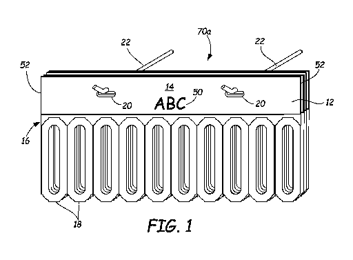
[0007] FIG. 1 is a front view of a first exemplary embodiment of an elastic
band package of the
present disclosure.
[0008] FIG. 2 is a front view of a single sheet assembly of elastic bands.
[0009] FIG. 3 is a partial cross sectional view of the sheet of FIG. 2, taken
along line 3-3 of
FIG. 2;
[0010] FIG. 4 is a front view of a second exemplary embodiment of an elastic
band package of
the present disclosure.
[0011] FIG. 5 is an enlarged partial view of a sheet assembly of elastic
bands.
[0012] FIG. 6 is a front view of a portion of an endless strip of elastic
bands in a second
exemplary embodiment of an elastic band package.
[0013] FIG. 7 is a side view of a spool including a rolled configuration of
the strip of FIG. 6.
CA 03059474 2019-10-08
WO 2018/217475 PCT/US2018/032240
4
[0014] FIG. 8 is a perspective view of another spool configuration of the
strip of FIG. 6, wherein
the spool core is wider than the strip.
[0015] FIG. 9 is a front view of another exemplary embodiment of a portion of
a sheet of elastic
bands useable in a package similar to that of FIG. 1.
[0016] FIG. 9A is an end view of the sheet of FIG. 9, as viewed from the right
side of FIG. 9.
[0017] FIG. 10 is a front view of a third exemplary embodiment of an elastic
band package of
the present disclosure.
[0018] FIG. 11 is a partial cross sectional view of a sheet of the package of
FIG. 10, taken along
line 11-11 of FIG. 10.
[0019] While the above-identified figures set forth one or more embodiments of
the disclosed
subject matter, other embodiments are also contemplated, as noted in the
disclosure. In all cases,
this disclosure presents the disclosed subject matter by way of representation
and not limitation.
It should be understood that numerous other modifications and embodiments can
be devised by
those skilled in the art that fall within the scope of the principles of this
disclosure.
[0020] The figures may not be drawn to scale. In particular, some features may
be enlarged
relative to other features for clarity. Moreover, where terms such as above,
below, over, under,
top, bottom, side, right, left, etc., are used, it is to be understood that
they are used only for ease
of understanding the description. It is contemplated that structures may be
oriented otherwise.
DETAILED DESCRIPTION
[0021] FIG. 1 is a front perspective view of an elastic band package 70a in a
first exemplary
embodiment. In an exemplary embodiment, package 70a is formed of layers of
overlaid band
sheets 12, one of which is shown in FIG. 2. Band sheets 12 of a package 70a
can be identical to
each other. The overlapping sheets 12 forming package 70a can be attached to
each other, such
as by the use of adhesive, mechanical fasteners such as clamps and rivets, or
other attachment
mechanisms. Moreover, as shown in FIGS. 1-5, each sheet assembly 12 includes a
header 14
attached to an elastic panel 16, which includes ruptureably connected elastic
bands 18. Header
14 is provided in some embodiments for ease of handling, and optionally for
carrying indicia 50.
However, in other embodiments, as shown in FIGS. 10 and 11, for example, an
elastic band
package 70c can includes layers of elastic panels 16 without header 14.
[0022] As shown in FIG. 1, one or more headers 14 of package 70a can include
an attachment
feature 20 such as an aperture configured for passage of a retention mechanism
such as retention
CA 03059474 2019-10-08
WO 2018/217475 PCT/US2018/032240
hook 22. In another embodiment, such an attachment feature 20 can be provided
on elastic panel
16 rather than on header 14. Attachment features 20 of the multiple layers of
elastic panel 16 or
headers 14 are aligned to allow such passage of a portion of retention
mechanism 22. Moreover,
while a particular configuration and placement of attachment features 20 is
illustrated, it is
contemplated that many other variations of attachment features can also be
used, including but
not limited to hooks, rivets, clips, other mechanical fasteners such as screws
and nails, brackets,
hook and loop fasteners, and adhesive, for example. Moreover, while the
illustrated attachment
feature 20 is provided in each of the band sheets 12, other attachment
features may be provided
singly for an entire package 70.
[0023] FIG. 2 is a front view of a single band sheet assembly 12. In an
exemplary embodiment,
elastic band package 70a is formed by overlaying many band sheets 12 together,
with headers 14
aligned in a stacked configuration. In an exemplary embodiment, elastic panel
16 is configured
as a layer of flexible elastomer material cut into a plurality of elastic
bands 18 ruptureably
connected to elastic strip 24. Such cutting can be performed by a laser
cutting apparatus, for
example. Any number of band sheets 12 can be provided in a package 70, to form
a package 70
of convenient size, weight, number of individual bands 18, and other
considerations for a
particular application. In an exemplary embodiment, package 70 can
additionally include a
relatively stiff backer card (not shown) to facilitate handling and packaging
of one or more
packages 70.
[0024] FIG. 4 is a front view of a second exemplary embodiment of an elastic
band package 70b
of the present disclosure. In this embodiment, band sheet assembly 12 has a
continuous header
14 and continuous elastic strip 24, to which elastic bands 18 are ruptureably
connected. In
package 70b, header 14 is folded at side edges 52 rather than being cut at
side edges 52. Thus,
package 70b is formed with layers of connected, overlapping portions of header
14 and elastic
panel 16. The layers can be optionally secured together, such as with adhesive
or mechanical
fasteners, for example, to form a coherent package 70b.
[0025] FIG. 5 is an enlarged partial view of a portion of sheet assembly 12 of
elastic bands 18.
In an exemplary embodiment, elastic panel 16 is cut so that each elastic band
18 is attached to
strip 24 at joints 26. Moreover, in the illustrated embodiment, each elastic
band 18 is fully
disconnected from each of the other elastic bands 18 to facilitate removal of
an individual elastic
band 18 from package 70. In an exemplary embodiment, an elastic band 18 is
substantially
CA 03059474 2019-10-08
WO 2018/217475 PCT/US2018/032240
6
configured as a loop surrounding aperture 28 and having loop width dimension
D. In the
illustrated embodiment, joints 26 are located at a top end of each elastic
band 18 (assuming that
package 70 is suspended via attachment features 20 in the depicted
orientation), though other
configurations are also possible.
[0026] In an exemplary method of manufacture, the contour of outer perimeter
cut 30 of each
elastic band 18 results in the formation of substantially triangular-shaped
elastic portions 54 as
part of elastic strip 24. Such elastic portions 54 may lend support to upper
ends of the adjacent
elastic bands 18. Excess elastomer material (i.e., "weed") resulting from the
cutting of aperture
28 is preferably removed. Excess elastomer material near the bottom ends of
elastic bands 18
and between adjacent elastic bands 18 (similar in configuration to elastic
portions 54) can also be
removed. Preferably, such removed weed material is not discarded but rather is
recycled and is
used as additional elastomer material for manufacturing elastic panel 16.
Moreover, aperture 28
may have a very narrow width (e.g., slit-like), so that very little weed is
removed.
[0027] As shown in FIG. 2, in an exemplary embodiment, each elastic band 18 is
formed to have
an overall width W that is less than its length L (wherein W and L are
measured in substantially
perpendicular directions), so that many elastic bands 18 can fit on a given
width of header 14 or
package 70. While a particular configuration is illustrated for elastic bands
18, it is contemplated
that other flat (i.e., sheet-like) band shapes are also suitable, including
for example, oval, oblong,
elliptical, circular, and other closed polygonal and curved shapes, whether
symmetrical or
asymmetrical. Moreover, each elastic band 18 can also include one or more
additional features,
such as a finger-pull gripping tab at a bottom or side of each elastic band
18, for example.
Aperture 28 can be shaped other than oblong. In the illustrated embodiment,
elastic band 18 has
a substantially consistent dimension D between outer perimeter cut 30 and
aperture 28.
However, it is contemplated that in other embodiments, such a dimension need
not be
substantially consistent.
[0028] As shown in FIG. 3, band sheet assembly 12 has header 14 joined along a
flat bond zone
32 with a flexible elastic panel 16, such as at strip 24. Band sheet assembly
12 is sheet-like in
the sense that the elastic panel 16 is formed of a web of elastomeric or other
elastic material that
is flat in character, and the header 14 is formed of a strip of sheet material
that is flat in character,
although they may be drapeable and floppy and thus not always displayed in
flat form. Header
CA 03059474 2019-10-08
WO 2018/217475 PCT/US2018/032240
7
14 and elastic panel 16 are joined so that the sheet character of each is
aligned with the sheet
character of the other, giving a total unitary sheet-like character to a band
sheet assembly 12.
[0029] Bond zone 32 is formed where header 14 overlies and overlaps elastic
panel 16. As
shown in FIGS. 1 and 2, in an exemplary embodiment, header 14 overlies elastic
panel 16 along
an entire lower edge of header 14 and an entire upper edge of strip 24 of
elastic panel 16. In an
exemplary embodiment, bond zone 32 is located at the entire overlapping
interface 33 between
header 14 and elastic panel 16. However, in other embodiments, header 14 and
elastic panel 16
may be bonded together only at portions of the overlapping interface 33. In an
exemplary
embodiment, header 14 does not cover an entirety of elastic strip 24; rather,
an exposed portion
56 (labeled in FIG. 5) of strip 24 is provided between a bottom edge 58 of
header 14 and
perimeter cut 30 of elastic bands 18. Provision of such an exposed portion 56
ensures that the
material and bonding of header 14 does not interfere with separation of
elastic bands 18 from
elastic strip 24 at joints 26 between portions of perimeter cut 30.
[0030] As shown in FIG. 3, in an exemplary embodiment, header 14 includes a
front surface 34
and an opposed rear surface 36. An adhesive layer 38 is optionally disposed on
rear surface 36
to allow attachment of overlaid headers 14 (of separate sheets 12 or a
continuous, folded sheet
12) to each other to form package 70a, 70b. Many adhesives are suitable, such
as known
pressure-sensitive adhesives. Moreover, an exemplary embodiment of band sheet
assembly 12
includes a release liner 40 disposed over the adhesive layer 38 to optionally
protect the adhesive
layer 38 from fouling and contamination prior to use.
[0031] The thickness of header 14 is great enough to give some body effect but
ideally will not
be greater than necessary to have the requisite strength for suspension by
attachment
mechanisms 20 and retention of elastic panel 16 during use without tearing.
Header 14 may also
carry appropriate indicia 50 to describe or identify a manufacturer of elastic
band package 70a,
70b, instructions for use, or other relevant information or images. Indicia 50
may include
informational or decorative matter to be printed, embossed, or otherwise
provided on header 14
or elastic panel 16. While illustrated as substantially rectangular, header 14
can be provided by
creative cutting of its outer perimeter to provide desired shapes and forms.
Moreover, an
enhanced visual presentation of an elastic band 18 can also be provided by
creative cutting of
outer perimeter cut 30 and aperture 28 to provide desired shapes and forms.
CA 03059474 2019-10-08
WO 2018/217475 PCT/US2018/032240
8
[0032] Header 14 in an exemplary embodiment is in the form of a strip of sheet
material,
including sheet material with holes or perforations therethrough (for example,
apertures 20 or
perforations or scoring to facilitate folding at package side edges 52). A
suitable sheet material
for header 14 is preferably relatively thin, generally not over about 15 mils
(0.015 inch or 0.38
mm) or about 20 mils (0.020 inch or 0.51 mm) in thickness. However,
thicknesses up to about
30 mils (0.030 inch or 0.76 mm) or about 40 mils (0.040 inch or 1.02 mm) can
be used. The
material should be flexible and pliable but is most preferably inextensible
(e.g., not stretchable
and not elastic) for most applications. For purposes of this disclosure, an
elastic material is one
that has an initial dimension in a relaxed state; the dimension increases
under tension, such as by
stretching; moreover, upon release of the tension force, the dimension returns
to, or nearly to, the
initial unstretched dimension. In an exemplary embodiment, the material for
header 14 is
sufficiently non-elastic and non-stretchy under hand-applied forces. For
example, the sheet
material for header 14 can have sufficient dimensional stability to carry a
reliably scannable (i.e.,
non-distorted) print of a UPC code as well as other human-readable or machine-
readable
markings.
[0033] In an exemplary embodiment, the sheet material for header 14 is
sufficiently water
resistant to not disintegrate and not significantly pucker, wrinkle, or
otherwise disfigure or
deform when placed in water. Moreover, in an exemplary embodiment, inks or
other printing
media used for indicia 50 are sufficiently water resistant to avoid
disintegration or destruction
when repeatedly subjected to water and washing operations (as is common for
produce displays
in supermarkets). The sheet material for header 14 also should be somewhat
tough in the sense
of being sufficiently tear resistant to deter damage to it during handling.
[0034] Suitable materials for forming the header 14 include paper,
polystyrenic thermoplastics,
polyolefinic thermoplastics, polyesters, and others. Exemplary suitable
thermoplastic materials
include polymers of styrene, ethylene, propylene, as well as a variety of
other monomers and
mixtures of monomers (e.g., to make co-polymers and ter-polymers, etc.). Sheet
thickness for
polyester plastics and some others can be quite thin, even down to the 3 mil
(0.08 mm) or 4 mil
(0.10 mm) range, and still exhibit the toughness and the practical non-
elasticity desired.
[0035] The polymers may be formulated so that printing inks are readily
accepted on the surface
of the sheet material. Polymers can also be treated with special surface
treatments to enhance
acceptance of printing inks. The exact structure and composition of suitable
sheet materials for
CA 03059474 2019-10-08
WO 2018/217475 PCT/US2018/032240
9
header 14 can vary widely. Any of a variety of commercially available inks
compatible with or
accepted on header 14 and retained thereon, and in any desired color, may be
used to print
indicia 50. In a case where it is desirable to use a water-soluble ink, a thin
film of water-
insoluble plastic may be applied over the ink to enhance water resistance of
the printed markings.
[0036] To increase impact resistance of header 14, a styrene-butadiene-styrene
impact modifier
can be useful in amounts up to about 40 percent of the weight of a polystyrene
material. Headers
14 of such material are highly stable against stretching. They have desired
flexibility balanced
by a slight stiffness that contributes to ease of handling during manufacture
and use. Such
headers 14 also can be reliably printed, especially when first subjected to a
surface treatment
such as, for example, a corona treatment such as available from Pillar
Technologies of Hartland,
Wisconsin, a division of Illinois Tool Works. The treatment enhances
wettability and adhesion
characteristics of inks and adhesives on plastic substrates.
[0037] In an exemplary embodiment, elastic panel 16 generally has a layer
thickness that is
greater than the thickness of the header 14 by at least about 20 percent up to
about four or five or
six times the thickness of the header 14 (as for example where a header 14
having a thickness of
only about 6 mils (0.15mm) to about 8 mils (0.20 mm) is employed). In an
exemplary
embodiment, a thickness of elastic panel 16 is greater than about twice the
thickness of header
14, but usually will not exceed about 30 mils (0.76 mm) or about 35 mils (0.89
mm) when the
header 14 thickness lies in what is expected to be the popular range of about
5 mils (0.13 mm) to
about 10 mils (0.25 mm). It is conceivable, of course, to form band sheet
assembly 12 with a
header thickness and elastic panel thickness approximately equal (especially
where one employs
fusion bonding for the bond zone 32 between the header material and the
elastic material). It is
also conceivable to use elastic layer thicknesses up to but not usually
greater than about 100 mils
(2.54 mm).
[0038] Referring to FIG. 5, in an exemplary embodiment, the plurality of
elastic bands 18 are
fully separated from each other and are connected to strip 24 only at joints
26. While the
illustrated embodiment shows two joints 26 connecting each elastic band 18 to
strip 24, it is
contemplated that other configurations of joining mechanisms can also be used,
including for
example, perforations, score lines, cut lines of full or partial depth, and
other mechanisms for
forming a ruptureable line or contour of weakness connecting an elastic band
18 to strip 24.
Moreover, while a particular shape and configuration of the joint 26 between
the elastic band 18
CA 03059474 2019-10-08
WO 2018/217475 PCT/US2018/032240
and strip 24 is illustrated, it is contemplated that other forms and shapes
can be used. As shown
in FIG. 5, an outer perimeter cut 30 is provided around each elastic band 18,
except in the areas
of joints 26.
[0039] In use, package 70 may be mounted by attachment features 20 to
retention mechanism
22, or by other features or fasteners to a convenient location in a packaging
facility, for example.
A user can then use one hand to tug gently at an individual elastic band 18 to
rupture the joints
26 holding that band to the strip 24 and the rest of package 70. Thus, an
individual band 18 is
easily removed for use without requiring a user to untangle a single band from
a mass of tangled
bands. After all the bands 18 of a package 70 have been removed, the headers
14 with attached
elastic strips 24 can be removed from retention mechanism 22 and a new package
70 mounted
thereon for use. While a particular embodiment of a retention mechanism 22 is
illustrated, it is
contemplated that package 70 can be suspended from, or otherwise attached to,
any of a variety
of holders including those located in a packaging facility or even on the
person of a user such as
on a utility belt, for example.
[0040] Upon breaking an individual elastic band 18 from elastic band package
70, elastic band
18 in an exemplary embodiment has sufficient elastic strength to permit
stretching of its loop
having an inner circumference defined by aperture 28 to at least three times
the size of the
relaxed, unstretched inner circumference without fracture of the elastic
material. The relaxed,
unstretched inner circumference will vary depending on the size of the opening
desired for the
loop. The relaxed unstretched inner circumference typically ranges from about
1.5 inches (38.1
mm) up to about 10 inches (254 mm) but is not limited to this typical range.
In this disclosure,
the term "circumference" is loosely used to refer to a perimeter of a closed
shape and thus is
applicable for describing an edge of an oval, elliptical or other closed
polygon or shape (whether
symmetrical or asymmetrical) that may or may not be circular.
[0041] A width dimension D of elastic band 18 between aperture 28 and outer
perimeter cut 30
is adequate to provide requisite strength for the elastic band 18 as it is
placed about a product or
bundle of products, such as produce that is sold in clumps or groups, for
example (not shown).
As shown in FIG. 5, an average loop width dimension D for elastic band 18 in
exemplary
embodiments falls within a range of at least about 0.10 inch (2.54 mm) up to
about 0.5 inch (12.7
mm). These widths are especially suitable for thicknesses of elastic panel 16
between about
0.012 inch (0.30 mm) and 0.030 inch (0.76 mm).
CA 03059474 2019-10-08
WO 2018/217475 PCT/US2018/032240
11
[0042] In an exemplary embodiment, materials for forming the elastic panel 16
are rubber-like in
character. The material desirably recovers from a stretched condition
relatively quickly;
however, instantaneous retraction or recovery to an original relaxed condition
and dimension
after stretching is not always critical for functional elastic performance.
Substantially
instantaneous retraction to a loop inner circumference dimension (defined by
aperture 28) no
greater than 5 percent above the original unstretched loop inner circumference
dimension
suffices for a multitude of uses. A substantially instantaneous loop
retraction is accomplished
when, after having been momentarily stretched to a predetermined extent, it
takes no more than 3
seconds for the loop to retract (i.e., recover) to an inner circumference size
no more than 5
percent greater than the inner circumference of the original unstretched loop.
A momentarily
stretched condition is one in which the stretch is not held for more than 3
seconds, and the
predetermined extent of the stretch is three times (or more) the inner
circumference of the loop in
unstretched relaxed condition. There may be occasions where retraction may
take possibly up to
about 10 seconds and still may constitute sufficiently quick retraction to be
useful as elastic
material for the purposes of this disclosure. Those skilled in the art of
elastic performance
features are capable of selecting materials such as elastomers possessing the
elastic stretch and
retraction characteristics desired for a particular use.
[0043] In selecting materials such as elastomers for elastic panel 16,
substantially instantaneous
retraction is most preferred for rapid bundling of products; slower retraction
may allow some
product to fall out of the bundle before retraction takes place. On the other
hand, a modestly
slower retraction may be quite adequate where elastic band 18 is to be
stretched about a single
product under conditions where speed of retraction (bounce back) is reliable
but not the
dominant consideration.
[0044] Particularly suitable elastomers are those that are thermoplastic in
that they at least soften
in response to heat, or even melt, to a flowable or moldable state. A
multitude of thermoplastic
elastomers are known and more are being created. A suitable family of
thermoplastic elastomers
includes styrenic block co-polymers. This family includes styrene-butadiene
styrene and
styrene-ethylene-butylene styrene. Another family of useful thermoplastic
elastomers include
olefinic elastomers, including those that are ethylene based as well as those
that are
polypropylene based (e.g., where interposed different monomer blocks are not
used but blocks of
different tacticity -- atactic and isotactic -- are created by using
metallocene catalysis
CA 03059474 2019-10-08
WO 2018/217475 PCT/US2018/032240
12
polymerization). Yet another family of thermoplastic elastomers include
polyvinyl chloride-
based elastomers. Still other families of thermoplastic elastomers can be
based on urethanes,
nylon, and silicon, for example.
[0045] Selection of an elastomer material may take into account factors such
as cost and bonding
compatibility with a material of header 14. Generally, similar materials tend
to bond together (as
by polymer bonding) better than dissimilar materials; and materials of like
polarity usually bond
better than materials of unlike polarity. Thus, header material selection can
be made from
polymers in the same family as the elastomer, such as those including at least
some monomers
related to, or the same as those present in, the elastomer chosen for the
elastic panel 16. Surface
treatments such as corona treatments also help to improve bonding. Still
further, compatibilizers
that adjust the polarity of material can be used to improve bonding.
Additional information is
described in U.S. Patent No. 8,635,795 to Ludlow et al., which is hereby
incorporated by
reference. A common practice in handling polymeric materials for header 14 and
elastic panel
16 is to add compatible (i.e., readily blendable) ingredients to achieve
desired properties such as
coloration, opacification, resistance to degradation on exposure to
environmental conditions,
improved impact properties and adhesion properties, for example.
[0046] In an exemplary embodiment, elastic panel 16 is substantially uniform
in composition
throughout its extent. On the other hand, header 14 may be a laminate of
different layers,
including a possible protective coating over a printed layer, especially a
printed layer that is
believed to need further protection against smudging or destruction.
[0047] Heat welding as by applying heat and pressure on overlapping
thermoplastic polymeric
materials forming header 14 and elastic panel 16 can be useful to form the
bond at bond zone 32.
Significant heat at the interface 33 of overlapping thermoplastic polymeric
materials can also
result in complete fusion between the polymer of header 14 and the polymer of
the elastic panel
16. Sonic welding is another way to unify the layers and achieve a cohesive
bond between
compatible parts. Laminating a molten elastomer to a molten (or at least
softened) header
material by co-extrusion is another way of forming bond zone 32. This method
can be
particularly effective where molecules or parts of molecules of the header
polymer and the
molten elastomer substrate material at the bond zone 32 interdiffuse with each
other. Bonds can
also be formed by interposing an intermediate layer at the bond zone 32 (e.g.,
a hot melt bonding
adhesive) to which both the header material and the elastic panel material
will readily bond
CA 03059474 2019-10-08
WO 2018/217475 PCT/US2018/032240
13
because of their compatibility to the intermediate material. Still further,
treatment of the surface
areas where bonding is to be accomplished can be effective. Even mechanical
bonding can be
effective, as where the header material is porous (e.g., paper and the porous
polymer product
called "Teslin"), and the elastomeric layer is applied in molten condition or
at least in a softened
condition and pressed into the voids or interstices of the porous header
layer. Any useful
bonding technique and structure that joins the header 14 with the elastic
panel 16 in a manner
forming a unifying flat bond zone 32 that can withstand delamination in
expected use is suitable.
[0048] In an exemplary embodiment, elastic band sheet assembly 12 has a high-
impact
polystyrene header 14 and an elastic panel 16 formed using a styrene-butadiene-
styrene (SBS)
block co-polymer available from GLS Corporation under the tradename "Kraton D-
2104." This
co-polymer has several beneficial features such as high clarity, good
dimensional stability, food
contact acceptability, relatively high strength, low viscosity, ease of
coloring, and high
elongation. To improve its adhesion to a styrenic header 14, an optional
addition of up to 10
percent by weight of polystyrene (based on the weight of the elastomer in the
composition) may
be blended in the elastomer composition for elastic panel 16. The composition
can easily be
colored, as for example by using polystyrene base color concentrates from
Clariant (of
Minneapolis, Minnesota) or by using polyethylene base color concentrates from
Ampacet (of
Tarrytown, New York) at concentrations of up to about 5 percent or more of the
weight of the
base styrene-butadiene-styrene block co-polymer.
[0049] Those skilled in the art will recognize that any suitable process for
the manufacture of the
new labeling articles of the invention can be employed. Batch processing is
useful for limited
production runs. Conveyor processing with indexing from station to station for
specific
operations can be useful, especially for uniquely designed or shaped headers
or elastic substrates.
An in-line web-based process is especially suitable for manufacturing a web of
multiple elastic
sheets 12 from the standpoint of economy. Moreover, while elastic band package
70a is shown
in FIG. 1 as a stack of separate, overlaid elastic sheet assemblies 12, it is
also contemplated that
an elastic package of the disclosure may have other configurations. For
example, as shown in
FIG. 4, package 70b may be formed of a continuous elastic sheet assembly 12
having a header
14 of indeterminate width (along the horizontal direction) that is folded in
an "accordion" style
along package side edges 52 to yield a package of multiple overlapping layers
or portions that
are all connected to each other at header 14 and elastic strip 24. As shown in
FIG. 10, as elastic
CA 03059474 2019-10-08
WO 2018/217475 PCT/US2018/032240
14
band package 70c may be formed of overlapping layers of elastic panel 16
without a header. The
overlapping layers of elastic panel 16 may be formed by stacking (similar to
the stack of cut
sheets of FIG. 1) or by folding (similar to the accordion folded configuration
of FIG. 4), for
example. An elastic band package (not shown) can also be provided in a spooled
configuration,
formed by rolling a continuous elastic sheet assembly 12 having a header 14 of
indeterminate
width (along the horizontal direction, as shown in FIG. 1) upon a spool core
or upon itself.
While the elastic panel 16 is generally thicker and flimsy, the relatively
stiffer but yet flexible
header 14 allows for reliable rolling, folding, stacking and other handling
procedures. Moreover,
an elastic band package (not shown) can also be provided in a spooled
configuration, formed by
rolling a continuous elastic panel 16 of indeterminate width (along the
horizontal direction) upon
a spool core (not shown) or upon itself.
[0050] FIG. 6 is a top view of a portion of a strip 42 of indefinite length of
ruptureably
connected elastic bands 18. In this case, joints 26 are provided between
adjacent elastic bands
18. FIG. 7 is a perspective view of a spool 44 including a rolled
configuration of strip 42. In
spool 44, strip 42 is wound upon an optional core and upon itself and in a
manner so that a width
of the spool 44 is substantially the same as the width W of a single elastic
band 18. In use, spool
44 can be held on a reel or other holder, to allow a user to pull an
individual end band 18 off
spool 44, and rupture the connections at joints 26, thereby separating the end
band 18 from an
adjacent band 18 on strip 42.
[0051] FIG. 8 is a perspective view of another embodiment of a spool 46,
having a core 48 of
greater width than the width W of strip 42. Such a spool configuration is
especially useful when
a very long strip 42 is desired. By winding strip 42 about a core 48 having a
greater width, the
thickness of the wound strip 42 upon core 48 can be reduced, thereby allowing
for easier
handling of the spool 46.
[0052] FIG. 9 is a front view of another exemplary embodiment of a portion of
a sheet 12' of
elastic bands 18 useable in a package 70. FIG. 9A is an end view of the sheet
12', taken from a
right side of FIG. 9. Sheet 12' of FIG. 9 is substantially similar to sheet 12
of FIGS. 1 and 2
except that a tag 60 is bonded to an end of each elastic band 18 at bond zone
62. Moreover,
elastic panel 16 is shown as overlaying front surface 34 of header 14. Tag 60
can be formed
from the same or similar materials, using the same or similar methods, as
header 14, discussed
above. Bond zone 62 can be the same or similar to bond zone 32, discussed
above. In an
CA 03059474 2019-10-08
WO 2018/217475 PCT/US2018/032240
exemplary embodiment, adjacent tags are disconnected from each other, so that
each band 18 is
connected to elastic strip 24 of sheet 12' only at joints 26. After an elastic
band 18 is detached
from strip 24 of elastic panel 16 by breaking joints 26, the elastic band with
attached tag 60 can
be used in the same manner as the labeling article of U.S. Patent 8,635,795 to
Ludlow et al; this
reference is fully incorporated herein.
[0053] FIG. 10 is a front view of a third exemplary embodiment of an elastic
band package 70c
of the present disclosure. FIG. 11 is a partial cross sectional view of an
elastic panel 16 of the
package 70c of FIG. 10, taken along line 11-11 of FIG. 10. In package 70c, no
header is used.
Rather, package 70c is formed with overlaid layers of elastic panel 16, which
may be stacked,
similar to the stacked configuration of package 70a of FIG. 1, or folded,
similar to the folded
configuration of package 70b of FIG. 4. Because no header is used, elastic
strip 24 may be taller
than shown in other configurations, to optionally provide space for attachment
features 20 or
indicia 50, for example. Elastic strip 24 is more easily viewed in this
embodiment of package
70c than the embodiments of package 70a or 70b including header 14.
Accordingly, this
description discusses some features of elastic panel 16 with reference to this
embodiment, though
it should be understood that these features also apply to all embodiments of
package 70.
[0054] In an exemplary embodiment, panel 16 of elastic material includes
elastic strip 24 having
opposed first and second longitudinal edges. The first longitudinal edge of
elastic strip 24 is
defined by the top portion of outer perimeter cuts 30. The second longitudinal
edge 64 of elastic
strip 24 is positioned at the top of the illustrated embodiments. A plurality
of elastic bands 18 are
rupturably connected to the first edge 26 of the elastic strip 24, each of the
bands 18 configured
as a loop surrounding a first aperture 28.
[0055] Overlapping portions of strip 24 of package 70c can be attached to each
other, such as by
the use of adhesive, mechanical fasteners such as clamps and rivets, or other
attachment
mechanisms. In an exemplary embodiment, an adhesive layer 38 is optionally
disposed on a
portion of a surface of elastic panel 16, such as a rear surface thereof, to
allow attachment of
overlaid portions of strips 24 (of separate elastic panels 16 or a continuous,
folded elastic panel
16) to each other to form package 70c. Many adhesives are suitable, such as
known pressure-
sensitive adhesives. Moreover, an exemplary embodiment of elastic panel 16
includes a release
liner 40 disposed over the adhesive layer 38 to optionally protect the
adhesive layer 38 from
fouling and contamination prior to use.
CA 03059474 2019-10-08
WO 2018/217475 PCT/US2018/032240
16
[0056] Those skilled in the art will readily recognize that the teachings of
this disclosure may be
embodied in specific forms other than those illustrated without departing from
the essential
described characteristics. The illustrated embodiments are therefore to be
considered in all
respects illustrative and not restrictive, the scope of the invention being
indicated by the
appended claims rather than the foregoing description, and all variations that
come within the
meaning and range of equivalency of the claims are therefore intended to be
embraced thereby.
[0057] Although the subject of this disclosure has been described with
reference to several
embodiments, workers skilled in the art will recognize that changes may be
made in form and
detail without departing from the scope of the disclosure. In addition, any
feature disclosed with
respect to one embodiment may be incorporated in another embodiment, and vice-
versa.