Note : Les descriptions sont présentées dans la langue officielle dans laquelle elles ont été soumises.
CATHETER INSERTION DEVICE
CROSS-REFERENCE TO RELATED APPLICATIONS
[0001] Deleted
TECHNICAL FIELD
[0002] This disclosure generally relates to medical devices for use in the
insertion of
catheters or other medical equipment into the vasculature of a patient. More
particularly, this
disclosure relates to a catheter insertion device for at least partial
insertion of a catheter within
the vasculature of the patient.
BACKGROUND
[0003] Different types of medical devices, such as needles, introducers,
trocars,
catheters, stents, angiography balloons, cutting tools, and imaging tools can
be introduced
into the body for various medical procedures. For example, catheters are used
to introduce or
remove fluids from vessels in the body for a variety of medical procedures. In
a typical
procedure, to insert a catheter in a vessel, the vessel access is first
verified by aspiration
using a long hollow needle, such as a syringe needle. A guidewire is then
passed through the
needle into the vessel. The guidewire acts as a track for the catheter to pass
over to reach a
target location within the vessel. A catheter is finally passed over the
guidewire to the target
location in the vasculature of the patient. With the catheter in place, the
needle and the
guidewire are removed, leaving only the catheter in the vessel. Fluids are
then introduced or
removed from the vessel through the catheter by connecting a fluid source or
aspiration
device to the catheter hub.
1
Date Recue/Date Received 2021-03-25
[0004] Various devices are known for placement of a catheter in the
vasculature of a
patient. Maintaining sterility of the various components of the device by, for
example,
preventing the contact of the fingers of the operator with the various parts
of the needle, the
guidewire, and the catheter itself during operation, is important for use of
these devices.
However, conventional catheter placement devices typically require the use of
two hands for
the insertion of the guide wire and advancement of the catheter into the
vasculature, which
increases the risk of contamination and also increases the risk of
inadvertently damaging the
vessel due to unintended needle point movement. Moreover, conventional
catheter
placement devices also prevent the continuous use of ultrasound from the point
of skin
penetration, vessel access, and wire guide insertion, through to having the
first distal portion
of the catheter in the vessel and needle point shielded. This makes such
conventional catheter
placement devices less convenient for use. Additionally, the aforementioned
drawbacks of
conventional catheter placement devices affect the success rate of insertion
into the
vasculature.
[0005] Therefore, a need exists for a novel catheter insertion device that
allows for
single-handed insertion of the catheter within the vasculature of the patient.
Additionally, a
need exists for a catheter insertion device that allows for easy, safe, and
fast catheter
placement into a patients vasculature.
SUMMARY
[0006] The foregoing needs are met, to a great extent, by implementations of a
catheter
insertion device according to the present disclosure. In accordance with one
implementation,
a catheter insertion device comprises a handle having a proximal body portion
and two
cantilever arms each extending distally from said body portion; a needle
cannula having a
proximal end located within the handle proximal body portion, said needle
cannula extending
distally from the handle proximal body portion and defining a distal
2
Date Recue/Date Received 2021-03-25
cantilever portion disposed partially between the two cantilever arms of the
handle; a catheter
assembly removably coupled to the handle and configured to slide on the needle
cannula, the
catheter assembly comprising an elongated catheter, a catheter hub connected
to a proximal
end of the elongated catheter, and a catheter advancer base releasably
connected to the
catheter hub; and a needle support having two parallel walls pivotally
connected to the
handle, said needle support pivoting between a first position and second
position, said needle
support configured to support the needle cannula on the cantilever portion of
said needle
cannula when the needle support is in the first position and said needle
cannula is disposed
between said two parallel walls of the needle support, said needle support
blocking distal
advancement of the catheter assembly when said needle support is in the first
position.
According to another general aspect, there is provided a catheter insertion
device
comprising: a handle having a body portion and an arm extending distally from
the body
portion; a needle cannula partially within the handle, the needle cannula
comprising a sharp
distal tip extending distally from the handle; a catheter assembly removably
coupled to the
handle, the catheter assembly comprising an elongated catheter, a catheter
advancer base
having a seat portion, and a catheter hub connected to the elongated catheter
and matingly
received in the seat portion of the catheter advancer base; and a needle
support connected
to the handle and movable between a first position and a second position, the
needle
support configured to stabilize lateral movement of the needle cannula when in
the first
position, and the needle support configured to block distal advancement of the
catheter
assembly when in the first position.
According to yet another general aspect, there is provided a catheter
insertion device
comprising: a handle having a body portion, a top arm extending distally from
the body
portion, and a bottom arm extending distally from the body portion; a needle
cannula
having a proximal end located within the handle body portion and a sharp
distal tip
extending distally from the top and bottom arms; a catheter assembly removably
coupled to
the handle and configured to slide on the needle cannula, the catheter
assembly having a
3
Date Recue/Date Received 2021-03-25
portion disposed in a space between the top arm and the bottom arm, the
catheter assembly
comprising an elongated catheter, a catheter hub connected to the elongated
catheter, and a
catheter advancer base removably connected to the catheter hub, the catheter
advancer base
having a grip portion for gripping and advancing the catheter assembly from a
first position
to a second position; a guidewire partially disposed within the handle; and a
guidewire
actuator connected to the handle and to the guidewire, the guidewire actuator
configured to
slide along the top arm of the handle for extending or retracting the
guidewire relative to the
handle.
Variants, examples and preferred embodiments of the invention are described
hereinbelow.
[0007] In some implementations, the catheter insertion device may comprise a
guidewire and a guidewire actuator for extending or retracting the guidewire,
wherein the
needle support cannot pivot away from the first position before the guidewire
actuator is
moved to extend the guidewire distally past a tip of the needle cannula.
[0008] In some implementations, the two arms of the handle comprise a top arm
and a
bottom arm, and the catheter advancer base slidably engages the bottom arm of
the handle.
[0009] In some implementations, the catheter advancer base may include a guide
track
configured to receive the bottom arm of the handle for moving the catheter
assembly in a
distal direction relative to the handle and in a proximal direction relative
to the handle, and
wherein the guide track prevents twisting of the catheter assembly during
movement of the
catheter assembly in both the distal and proximal directions.
[0010] In some implementations, the catheter advancer base may include a pair
of grip
arms for supporting a choked-up hand position by a user.
3a
Date Recue/Date Received 2021-03-25
CA 03059619 2019-10-09
WO 2018/191361
PCT/US2018/027078
[0011] In some implementations, the needle support is pivotally connected to a
distal
portion of the top arm of the handle and configured to move relative to the
handle upon
abutment of the catheter advancer base to the needle support.
[0012] In some implementations, the needle support is configured to pivot
relative to
the handle about a pivot axis perpendicular to an axis of the needle cannula.
[0013] In some implementations, the needle support may further comprise a hook
portion configured to releasably mate with the bottom arm of the handle when
said needle
portion is in the first position.
[0014] In some implementations, moving the guidewire actuator in a proximal
direction relative to the handle causes a distal end of the guidewire to move
in a distal
direction away from the handle, and moving the guidewire actuator in a distal
direction
relative to the handle causes the distal end of the guidewire to move in a
proximal direction
towards the handle.
[0015] In some implementations, the catheter insertion device may comprise a
catheter assembly actuator connected to the handle, the catheter assembly
actuator being
movable relative to the handle to push the catheter assembly distally relative
to the handle.
[0016] In some implementations, the catheter advancer base may further
comprise a
seat portion configured to stably secure the catheter and catheter hub.
[0017] In some implementations, the catheter advancer base may further
comprise a
retaining member configured to secure the catheter hub.
[0018] In some implementations, the needle support may further comprise a
textured
surface to aid gripping.
[0019] In some implementations, the needle cannula may further comprise a
sharp
distal tip extending distally from the handle, the distal tip having a back-
grind portion
defining a gradual taper.
4
CA 03059619 2019-10-09
WO 2018/191361
PCT/US2018/027078
[0020] In some implementations, the guidewire further has a variable
stiffness.
[0021] In some implementations, the needle cannula further comprises a swage
having an oval-shaped cross section bulge near a distal tip of the needle
cannula.
[0022] In some implementations, a catheter insertion device comprises: a
handle
having a body portion and an arm extending distally from the body portion; a
needle cannula
partially within the handle, the needle cannula comprising a sharp distal tip
extending distally
from the handle; a catheter assembly removably coupled to the handle, the
catheter assembly
comprising an elongated catheter, a catheter advancer base having a seat
portion, and a
catheter hub connected to the elongated catheter and matingly received in the
seat portion of
the catheter advancer base; and a needle support connected to the handle and
movable
between a first position and a second position, the needle support configured
to stabilize
lateral movement of the needle cannula when in the first position, and the
needle support
configured to block distal advancement of the catheter assembly when in the
first position.
[0023[ In some implementations, the needle support is configured to permit
distal
advancement of the catheter assembly when in the second position.
[0024] In some implementations, the catheter insertion devices further
comprises a
guidewire partially disposed within the handle, and a first actuator connected
to the handle
and the guidewire, the first actuator movable between an extended position
where the first
actuator abuts the needle support when the needle support is in the first
position, and a
retracted position where the first actuator does not abut the needle support
when the needle
support is in the first position, and wherein moving the first actuator
between the extended
and retracted positions causes the guidewire to move relative to the handle.
[0025] In some implementations, the catheter insertion device further
comprises a
second actuator connected to the handle and configured to move the catheter
assembly
CA 03059619 2019-10-09
WO 2018/191361
PCT/US2018/027078
distally relative to the handle and move the needle support from the first
position to the
second position when the first actuator does not abut the needle support.
[0026] Certain implementations of the catheter insertion device have been
outlined so
that the detailed description below may be better understood. There are, of
course, additional
implementations that will be described below and which will form the subject
matter of the
claims. In this respect, it is to be understood that the catheter insertion
device is not limited
in its application to the details of construction and to the arrangements of
the components set
forth in the following disclosure or illustrated in the drawings. Also, it is
to be understood
that the phraseology and terminology employed herein are for the purpose of
description and
should not be regarded as limiting. As such, the conception upon which this
disclosure is
based may readily be utilized as a basis for the designing of other
structures, methods, and
systems for carrying out the several purposes of the catheter insertion
device. It is
understood, therefore, that the claims include such equivalent constructions
insofar as they do
not depart from the spirit and scope of the present disclosure.
BRIEF DESCRIPTION OF THE DRAWINGS
[0027] FIG. lA illustrates a top perspective view of an implementation of a
catheter
insertion device including a catheter group and an insertion group.
[0028] FIG. 1B illustrates a side elevation view of the catheter insertion
device of
FIG. 1A.
[0029] FIG. 2A illustrates an exploded view of the separate components of the
catheter group of the catheter insertion device.
[0030] FIG. 2B illustrates a partially transparent perspective view of the
assembled
catheter group of the catheter insertion device.
[0031] FIG. 3A illustrates a partially exploded view of the catheter insertion
device.
6
CA 03059619 2019-10-09
WO 2018/191361
PCT/US2018/027078
[0032] FIG. 3B illustrates a top perspective view of the catheter insertion
device
having a protective needle guard.
[0033] FIG. 3C illustrates a side elevation view of the catheter insertion
device
having a protective needle guard.
[0034] FIG. 3D illustrates an enlarged bottom perspective view of a portion of
the
catheter insertion device.
[0035] FIG. 3E illustrates an enlarged top perspective view of a portion of
the
catheter insertion device.
[0036] FIG. 3F illustrates an enlarged side elevation view of a portion of the
catheter
insertion device.
[0037] FIG. 3G illustrates the catheter insertion device having a slider in a
retracted
position and a needle support in an upright position.
[0038] FIG. 3H illustrates an enlarged bottom perspective view of a portion of
the
catheter insertion device having a protective needle guard.
[0039] FIG. 4A illustrates a top perspective view of a catheter advancer base
and a
needle support.
[0040] FIG. 4B illustrates a top perspective view of the catheter advancer
base, the
needle support, and the assembled catheter group.
[0041] FIG. 5A illustrates a cross-sectional side view of a right housing of
an
assembled catheter insertion device.
[0042] FIG. 5B illustrates a cross-sectional view of a handle of an assembled
catheter
insertion device.
[0043] FIG. 6 illustrates a side elevation view of a portion of a slider of
the insertion
group of the catheter insertion device.
7
CA 03059619 2019-10-09
WO 2018/191361
PCT/US2018/027078
[0044] FIG. 7A illustrates a release of the insertion group of the catheter
insertion
device and a catheter advancer base, as well as a partial cut-away view of a
handle of the
catheter insertion device.
[0045] FIG. 7B illustrates an enlarged view of the release of the insertion
group of the
catheter insertion device without the catheter advancer base.
[0046] FIG. 7C illustrates a side view of the release in an extended position.
[0047] FIG. 8A illustrates a perspective view of a region of the assembled
catheter
insertion device having the slider in a fully extended position and the
release in a fully
retracted position.
[0048] FIG. 8B illustrates a cross-sectional side view of a region of the
catheter
insertion device along the center longitudinal plane of the handle in a pre-
advanced position
of the catheter group.
[0049] FIG. 8C illustrates a cross-sectional side view of the region of the
catheter
insertion device along the center longitudinal plane of the handle following
actuation of the
slider by the practitioner.
[0050] FIG. 8D illustrates a cross-sectional side view of the region of the
catheter
insertion device along the center longitudinal plane of the handle following
actuation of the
release by the practitioner.
[0051] FIG. 8E illustrates a cross-sectional side view of the region of the
catheter
insertion device along the center longitudinal plane of the handle following
further
advancement of the catheter group along the handle by the practitioner.
[0052] FIG. 8F illustrates a side view of the region of the catheter insertion
device
following advancement of the catheter group from the handle by the
practitioner.
[0053] FIG. 9A illustrates a perspective view of a needle safety clip mounted
to a
catheter hub of the catheter group of the catheter insertion device.
8
CA 03059619 2019-10-09
WO 2018/191361
PCT/US2018/027078
[0054] FIG. 9B illustrates a rear view of the needle safety clip.
[0055] FIG. 9C illustrates a front view of the needle safety clip.
[0056] FIG. 9D illustrates an enlarged perspective view of the needle safety
clip
released from the catheter hub of the catheter group of the catheter insertion
device.
[0057] FIG. 9E illustrates a perspective view of an implementation of a sharp
needle
tip of the needle according to the present disclosure.
[0058] FIG. 9F illustrates the sharp needle tip being withdrawn from the
needle safety
clip.
[0059] FIG. 10A illustrates the insertion group being pulled proximally to the
point
where the sharp needle tip of the needle is between two distal walls of the
needle safety clip.
[0060] FIG. 10B illustrates the insertion group being pulled proximally to the
point
where the sharp needle tip of the needle is proximal of both the two distal
walls of the needle
safety clip and is tilted relative to the needle safety clip.
[0061[ FIG. 11A illustrates a perspective view of an implementation of a seal
having
two parts according to the present disclosure.
[0062] FIG. 11B illustrates a proximal part of the two-part seal of FIG. 11A.
[0063] FIG. 11C illustrates a distal part of the two-part seal of FIG. 11A.
[0064] FIG. 11D illustrates a partial cross-sectional view of seal of FIG. 11A
within
the catheter hub of the catheter group.
[0065] FIG. 12 illustrates a perspective view of a distal region of the needle
showing
a plurality of echogenic features.
[0066] Implementations of the catheter insertion device are described with
reference
to the drawings, in which like reference numerals refer to like parts
throughout.
9
CA 03059619 2019-10-09
WO 2018/191361
PCT/US2018/027078
DETAILED DESCRIPTION
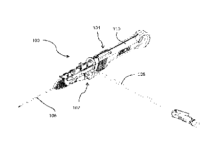
[0067] Referring to FIGS. lA and 1B, an implementation of a catheter insertion
device 100 including a catheter group 102 and an insertion group 104 is
illustrated. The
insertion group 104 may be separated from the catheter group 102 following
partial insertion
of a catheter 106 in the vasculature of a patient. The catheter group 102 also
includes an
extension line assembly 108 in fluid communication with the catheter 106. The
extension
line assembly 108 may be connected to a fluid source or an aspiration device.
The insertion
group 104 includes a handle 110 that is initially connected to the catheter
group 102 and that
facilitates the insertion of the catheter 106 in the vasculature of the
patient.
[0068] FIG. 2A illustrates an exploded view of the separate components of the
catheter group 102 of the catheter insertion device 100. Referring to FIG. 2B,
a partially
transparent perspective view of the assembled catheter group 102 of the
catheter insertion
device 100 is illustrated. At its proximal region, the catheter group 102
includes an extension
line assembly 108 that includes an elongated extension line 112, an extension
line clamp 114,
and an extension line hub 116. A vent plug, as shown in FIG. 1A, may further
be attached to
the extension line hub 116 during insertion of the needle and then removed
prior to use by the
practitioner, i.e. before the practitioner connects a syringe to the extension
line hub 116. The
elongated extension line 112 defines an elongated lumen that is in fluid
communication with
the lumen defined by the catheter 106 through the lumen defined by a rigid hub
120. The
extension line clamp 114 is received around the elongated extension line 112
and may be slid
in a direction perpendicular to the longitudinal axis of the elongated
extension line 112 to
pinch the elongated extension line 112 closed. When the extension line clamp
114 pinches
the elongated extension line 112, fluid is prevented from flowing beyond the
extension line
clamp 114 either distally towards the catheter 106 or proximally towards the
extension line
hub 116. The extension line hub 116 defines a lumen that is in fluid
communication with the
lumen defined by the elongated extension line 112.
[0069] In some implementations, the lumen defined by the extension line hub
116 may be
tapered from its proximal end towards its distal end, white in other
implementations, the lumen
defined by the extension line hub 116 may have a uniform diameter. The
proximal end of the
extension line hub 116 includes a connector, such as a threaded tuer lock, for
connection to a
fluid source or an aspiration device. The fluid source may be a syringe or an
intravenous bag,
among others.
[0070] At its distal end, the catheter group 102 includes the elongated
catheter 106 that
is connected to a catheter hub 118. In particular, the proximal end of the
elongated catheter
106 connects to the distal end of the catheter hub 118. The rigid hub 120 is
partially received
within the proximal end of the catheter hub 118. The rigid hub 120 receives a
seal 218 that
acts as a valve within an internat cavity defined by the rigid hub 120. The
proximal end of the
rigid hub 120 is sealed by a rigid hub cap 124. The proximal end of the rigid
hub cap 124 has
an opening that allows the needle cannula 130 and the guidewire 132 to pass
through the
rigid hub cap 124 to the seal 218. The elongated catheter 106 defines an
elongated lumen that
is at least partially received within the vasculature of the patient. The
catheter hub 118
defines a tapered cavity that is in fluid communication with the lumen defined
by the
elongated catheter 106 and the lumen defined by the rigid hub 120. The rigid
hub 120 also
includes a side port 121 for receiving the elongated extension line 112 of the
extension line
assembly 108. The lumen defined by the side port 121 is in fluid communication
with the
lumen defined by the elongated extension line 112.
[0071] The seal 218 is a multi-piece seal, as described in greater detail
below. In other
implementations, the seal may be one-piece seal, as described in U.S. Patent
Application No.
14/306,698, filed June 17, 2014.
11
Date Recue/Date Received 2021-03-25
When the catheter group 102 is assembled, the seal 218 is enclosed by the
rigid hub 120 and
the rigid hub cap 124. In some implementations, the catheter group 102 may not
include the
extension line assembly 108 and the fluid source or aspiration device can be
connected to a
proximal end of the rigid hub 120.
[0072] Referring to FIG. 3A, an exploded view of the separate components of
the
insertion group 104 of the catheter insertion device 100 is illustrated along
with an assembled
view of the catheter group 102. FIGS. 3B and 3C illustrate a perspective view
and a side
view, respectively, of the assembled catheter group 102 and insertion group
104 of the
catheter insertion device 100. The insertion group 104 includes the handle 110
that is made up
of a right housing 126 and a left housing 128 that are connected together. Top
arm 127 and
bottom arm 129 are formed in the distal region of the handle 110. A needle
cannula 130 is
held within the handle 110 and a guidewire 132, which slides through the lumen
defined by
the needle cannula 130, is also held within the handle 110. The needle cannula
130 may be
anchored within the handle 110 by an interference fit within an inner channel
defined by the
handle 110, by an adhesive, by a threaded connection, or the like. In some
implementations,
the needle cannula 130 may be, for example, a 24-gauge needle.
[0073] A needle safety clip 134 is placed around the outer surface of the
needle cannula
130 to cover the sharp needle tip 131 following separation of the insertion
group 104 from the
catheter group 102. A needle guard 137 covers the portion of the needle
cannula 130
extending from the handle 110 before initial use of the catheter insertion
device 100. A first
actuator, such as a slider 138, is connected to the top of the handle 110 and
to the guidewire
132 and slides the guidewire 132 relative to the handle 110 in both proximal
and distal
directions. In some implementations, the guidewire 132 may be a spring wire
guide, such as a
coiled or a coil-less spring wire guide. The length of the guidewire 132 is
selected
12
Date Recue/Date Received 2021-03-25
CA 03059619 2019-10-09
WO 2018/191361
PCT/US2018/027078
such that, before the slider 138 is actuated, the distal end of the guidewire
does not extend
beyond the sharp needle tip 131 of the needle cannula 130.
[0074] The guidewire 132 may have a variable stiffness, as discussed in
further detail
below. In some implementations, the guidewire 132 may have an outer diameter
that is
substantially uniform and less than or equal to 0.010 inches (0.0254
centimeters). Preferably,
the guidewire 132 has an outer diameter that is less than or equal to 0.010
inches when the
needle cannula 130 is a 24 GA needle and the elongated catheter 106 is a 22 GA
catheter, so
that the guidewire 132 may fit within the lumen defined by the 22 GA catheter.
In other
implementations, the guidewire 132 may have a varying diameter that narrows
distally, such
that the diameter of the guidewire 132 is the smallest at a distal end of the
guidewire 132.
When the guidewire 132 is fully advanced, the larger diameter section is
immediately distal
to the needle 130, which helps to guide the catheter 106 during advancement
and also directs
the catheter's movement during the initial part of the advancement. Further,
the distal tip of
the guidewire 132 has a small outer diameter so that it is sufficiently
flexible to help the
guidewire 132 travel a tortuous path out of the needle 130 and into the lumen
of the vessel.
The guidewire also comprises a large diameter tip, such as a tip shaped like a
ball so that it is
not sharp. Such a large ball-shaped tip helps the clinician determine whether
the entire
guidewire is removed after use, since the clinician can see if the ball is
there, thus indicating
that no piece of the guidewire was left behind. Moreover the ball-shaped tip
at the distal end
of the guidewire 132 is not sharp so as to avoid puncturing a patient's
vasculature during
operation.
[0075] In some implementations, the guidewire 132 may be made of a metal, such
as
a metal alloy. For example, the guidewire 132 may be made of an alloy of
nickel and
titanium. In some implementations, the guidewire 132 may be coated with
polysulfones,
polyfluorocarbons, polyolefins, polyesters, polyurethanes, blends and/or
copolymers.
13
CA 03059619 2019-10-09
WO 2018/191361
PCT/US2018/027078
[0076] A second actuator, such as a release 140, is also connected to the
handle 110
of the insertion group 104 and to the catheter group 102. The release is
configured to slide
the catheter group 102 relative to the handle 110 in a distal direction. The
release 140
includes a proximal arm 174 having an enlarged proximal end 141. A needle
support 142 is
attached to a proximal region of the handle 110 and swings upward and downward
relative to
the handle 110. In particular, the needle support 142 is rotationally coupled
to the top arm
127 by a pivot member 144.
[0077] A catheter advancer base 318 is removably connected to the catheter hub
118
and configured to slidably engage the bottom arm 129 of the handle 110, as
illustrated in FIG.
3D. The needle support 142 may comprise a rigid plastic material to support
the needle
cannula 130 from bending during insertion into a patient's vasculature. The
needle support
142 includes two parallel walls 143 separated by a distance slightly greater
than the outer
diameter of the elongated catheter 106 in which the needle cannula 130 passes
in order to
stabilize lateral movement of the needle cannula 130 during insertion of the
needle in the
vasculature of the patient. This stabilization is especially important for
insertion of the
needle relatively deep in the tissue of the patient, such as within an organ
of the patient.
Additionally, the needle support may further include a textured outer surface
to aid gripping
by a practitioner during insertion of the catheter into the vasculature of a
patient. Examples
of such a textured outer surface include various patterns of protrusions,
divots, grooves,
channels and bumps, among others. In other implementations, the textured
surface may be
formed of a different material, such as rubber, or may be formed as a
roughened surface
directly on the needle support 142. In some implementations, such examples of
a textured
surface may also be added to regions of the catheter advancer base 318, such
as to a grip arm
321 or grip recess 322, among other areas, in order to aid with gripping.
14
CA 03059619 2019-10-09
WO 2018/191361
PCT/US2018/027078
[0078] As illustrated in FIGS. 3E and 3F, the needle support 142 also includes
atop
portion 147 that abuts the bottom surface of the slider 138 before the slider
is slid proximally
in order to prevent swinging of the needle support 142 while the catheter
insertion device 100
is being inserted in the vasculature of the patient. A lip 149 may be provided
on the needle
support 142 that defines a seat region configured to hook around a distal end
of the bottom
arm 129 of the housing in order to prevent the needle 130 and/or the catheter
106 from
popping out of the needle support 142 prematurely. Further, the needle support
142 may
comprise a trapezoidal or other geometric shape, and may have an extended
longitudinal
length, for example 2 cm, configured to provide additional support to the
catheter.
[0079] As shown in FIG. 3G, the needle support 142 is free to swing about a
pivot
member 144 when the slider 138 is retracted to the extent in which it no
longer abuts the top
portion 147 of the needle support. The catheter advancer base 318 is
configured to receive
the catheter hub 118 of the catheter group 102, as will be discussed in
greater detail below. A
retaining member, such as a protruding clip 323, is provided on the catheter
advancer base
318 and is configured to further secure the wings of the catheter hub 118 to
help retain the
catheter hub 118 to the catheter advancer base 318 during deployment.
[0080] Referring to FIG. 3H, the needle guard 137 includes an open channel 260
defined by two parallel side walls 262. A bottom longitudinal feature and a
top longitudinal
feature between the parallel side walls 262 secure around the needle cannula
130. As such,
the bottom and top longitudinal features are spaced apart by a distance
slightly greater than
the outer diameter of the catheter 106. A tab 268 may be provided at the
proximal end of the
needle guard 137 to allow the practitioner to initially lift the needle guard
137 out of contact
with the slider 138, and then push the needle guard 137 distally until the
proximal ends of the
bottom and top longitudinal features are distal of the sharp needle tip 131.
At this point, the
CA 03059619 2019-10-09
WO 2018/191361
PCT/US2018/027078
needle guard 137 disengages from the insertion group 104 and may be removed to
expose the
sharp needle tip 131.
[0081] Referring to FIG. 4A, the catheter advancer base 318 and the needle
support
142 are shown isolated from the rest of the catheter insertion device 100.
FIG. 4B shows the
catheter group 102 engaged with the catheter advancer base 318 and the needle
support. An
upper surface of the catheter advancer base 318 includes a catheter seat 319
configured to
matingly receive the catheter hub 118. In one implementation, the retaining
member 323
may be configured to allow the catheter hub 118 to securely snap into the
catheter seat 319.
A pair of spaced apart fasteners, such as pins 320, are provided within the
catheter seat 319
for connecting to respective connector holes on each wing section, which
extend outwardly
on opposing sides of the catheter hub 118. The catheter hub 118 stays
connected to and
moves with the catheter advancer base 318 when the catheter advancer base is
advanced
distally during the catheter insertion procedure, as will be discussed in
detail below.
[0082] The catheter advancer base 318 may be disconnected and removed from the
catheter hub 118 during dressing of the catheter 106 to a patient. The
catheter advancer base
318 is also configured to stay with the catheter 106 during advancement and
may
disconnected therefrom during dressing. A longitudinal slide groove 324
provided on the
bottom surface of the catheter advancer base 318 defines a guide track that is
configured to
slidingly engage the bottom arm 129 of the housing. This guide track is
configured to create
a sliding motion of the catheter advancer base 318 along the bottom arm 129
and also prevent
twisting of the catheter advancer base 318 and catheter hub 118 about their
longitudinal axis
during such sliding motion when they are advanced forward during catheter
insertion.
Accordingly, the guide track is configured prevent torsion of the catheter
advancer base 318,
and thus also prevent torsion of the catheter group 102 and its associated
components, when
16
CA 03059619 2019-10-09
WO 2018/191361
PCT/US2018/027078
the catheter advancer base rides on the bottom arm 129 of the handle during
catheter
insertion.
[0083] A grip arm 321 is provided on each side of the catheter advancer base
318, and
a grip recess 322 is also provided on each side of the catheter advancer base
318. The grip
arms 321 and grip recesses 322 allow for alternate grip positions of the
catheter advancer
base 318 by a practitioner, including a choked up hand grip position. For
instance, in such a
choked up hand position, the user may grip the catheter insertion device 100
using one hand
by placing a thumb in the grip recess 322 located on a first side of the
catheter advancer base
318, and a middle finger in the grip recess 322 located on an opposite second
side of the
catheter advancer base 318. The user's index finger may then be curled up so
that it can
manipulate the slider 138. In this choked up hand position, the closer a
user's hand is located
toward the distal end of the handle allows for improved control of gripping
and advancing the
catheter advancer base 318 during operation. The catheter advancer base 318
may be
symmetric about its longitudinal axis to allow for both right-handed and left-
handed
placement by a user.
[0084] Referring to FIG. 5A, a cross-sectional side view of the right housing
126
including the slider 138 and the guidewire 132 is illustrated. The handle 110
includes a
looped proximal end 151 through which the guidewire 132 passes. In particular,
the
guidewire 132 passes through the channel 153 defined by the handle 110. The
diameter of
the channel 153 is slightly greater than the diameter of the guidewire 132 so
that the
guidewire 132 stably passes through the channel 153. The slider 138 can be
slid by a finger,
such as the index finger in overhand operation or the thumb in underhand
operation, of a
practitioner proximally and distally within a chamber 157 defined by the
handle 110. The
chamber 157 is sized to be slightly larger than the slider 138 to stabilize
the movement of the
slider 138 within the chamber 157.
17
CA 03059619 2019-10-09
WO 2018/191361
PCT/US2018/027078
[0085] Due to the looping of the guidewire 132 within the looped proximal end
151,
proximal movement of the slider 138 translates into distal movement of the
distal tip of the
guidewire 132 and vice versa. The looping of the guidewire 132, as opposed to
a linear
geometry, also enables one-handed operation of the catheter insertion device
100 while
maintaining continuous grip of the gripping features 148 of the handle 110. In
addition, the
looping of the guidewire 132 reduces the likelihood of piercing the
vasculature of the patient
during advancement of the guidewire 132 due to the force of the practitioner
being indirectly
applied to the guidewire 132.
[0086] Referring to FIG. 5B, a cross-section view of the assembled handle 110
with
the guidewire 132 and the slider 138 is illustrated. The handle 110 includes
gripping features
148 that help the practitioner grip the handle 110 of the catheter insertion
device 100. A
right-handed practitioner can, for example, grip the gripping feature 148 on
the left housing
128 using his thumb and grip the gripping feature 148 on the right housing
using his middle
finger. Alternatively, a left-handed practitioner can, for example, grip the
gripping feature
148 on the left housing 128 using his middle finger and grip the gripping
feature 148 on the
right housing using his thumb. The handle 110 can be gripped by the
practitioner overhand
or underhand using the same fingers. The gripping feature 148 may comprise a
plurality of
depressed lines, grooves, corrugations, projections, or a roughened surface,
among others,
formed on the outer surface of the handle 110. For example, raised lines may
be formed in
place of the depressed lines, a textured surface may be formed, a plurality of
bumps may be
formed, or a different material, such as rubber, may be provided over the
region of the handle
110 corresponding to the gripping features 148.
[0087] Three openings are defined by the front face 150 of the handle 110. The
bottom opening 152 is sized to receive the rigid hub cap 124 of the catheter
group 102. In
particular, the diameter of the bottom opening 152 is slightly greater than
the diameter of the
18
CA 03059619 2019-10-09
WO 2018/191361
PCT/US2018/027078
rigid hub cap 124. The middle opening 154 is sized to receive the guidewire
132 and the
needle cannula 130, and the top opening 156 is sized to receive the slider 138
and the
proximal arm 174 of the release 140. The top opening 156 includes a wider
bottom region
that receives the slider 138 and a narrower top region that receives the
proximal arm 174 of
the release 140. The bottom opening 152 and the middle opening 154 are
separated by a
portion of the handle 110, whereas the middle opening 154 and the top opening
156 are not
separated to allow a bottom arm 158 of the slider 138 to slide within middle
opening 154, as
explained in greater detail below.
[0088] In particular, referring to FIG. 6, a transparent side view of a
portion of the
slider 138 is illustrated. The slider 138 includes a bottom arm 158 extending
from the bottom
of the slider 138 in a direction perpendicular to the longitudinal axis of the
slider 138. The
bottom arm 158 includes a through hole 160 that receives the proximal end 133
of the
guidewire 132. The proximal end 133 may include a ball 162 to anchor the tip
of the
proximal end of the guidewire 132 in place. The through hole 160 has an
internal diameter
that is slightly larger than the outer diameter of the guidewire 132 but
slightly smaller than
the diameter of the ball 162 formed at the tip end of the guidewire 132. The
guidewire 132 is
therefore secured within the through hole 160 by an interference fit. The
through hole 160
does not extend along the entirety of the length of the bottom arm 158, such
that the distal
end of the through hole 160 is closed. Although the ball 162 is secured within
the through
hole 160 by an interference fit, in some implementations, the ball 162 may be
secured by an
adhesive, by a threaded connection, or the like.
[0089] Due to the interference fit between the through hole 160 and the
guidewire
132, as the slider 138 is moved in a longitudinal direction for a given
distance, the guidewire
will also move in the opposite direction for the same distance and vice versa.
Stated another
way, the portion of the guidewire 132 that is between the slider 138 and the
loop portion in
19
CA 03059619 2019-10-09
WO 2018/191361
PCT/US2018/027078
the handle will move in the same direction as the slider itself. Conversely,
the portion of the
guidewire 132 that is between the loop portion of the handle and the distal
tip will move in
the opposite direction of the slider 138. The slider 138 includes one or more
grips 164 that
allow a finger, such as the index finger in an overhand operation or the thumb
in an
underhand operation, of the practitioner to predictably actuate the slider 138
in either a distal
or proximal direction. In some implementations, the grips 164 may be shaped
like arrows
that point in the proximal direction. Adjacent to each grip 164 may be an
indicator 166, such
as a number, that indicates a relative extension of the guidewire 132 distally
from the sharp
needle tip 131.
100901 The guidewire 132 may further comprise a variable stiffness that
facilitates
insertion of the catheter 106 into the vasculature of a patient. In one
implementation, the
guidewire 132 may comprise various segments, such as a first segment defining
a thin section
of increased flexibility, a second segment defining a tapered transitioned
section, and a third
segment defining a thick and rigid section that assists the catheter 106 in
following bends in
the guidewire 132. The third segment, which is nearest to the catheter 106
when the variable
stiffness guidewire is fully extended, has the most stiffness which helps the
catheter more
easily follow any bends of the guidewire during insertion into a patient's
vasculature. The
stiffness gradually decreases towards the distal tip of the guidewire, such
that the first
segment is the most flexible region since it has the smallest diameter, which
may be, for
example, between .005 in and .006 in. The increased flexibility of the first
segment allows it
to easily bend upon entry into the vasculature in order to minimize piercing
through the
vasculature wall. As previously noted above, the ball-shaped distal tip of the
guidewire 132
also helps minimize such piercing through the vasculature wall. The length of
the segment of
the guidewire may vary. In one implementation, for example, the length of the
first and third
CA 03059619 2019-10-09
WO 2018/191361
PCT/US2018/027078
segments may be approximately 1.5 cm, and the length of the second segment may
be
approximately 1.0 cm.
[0091] FIG. 7A shows a portion of the catheter insertion device depicting the
release
140 and the catheter advancer base 318, and FIG. 7B shows a portion of the
catheter insertion
device depicting the release 140 without the catheter advancer base 318. The
distal side of
the release 140 includes a notch 168 configured to receive the side port 121
of the rigid hub
120. The release 140 is sized to be received from around the bottom arm 129 to
the slider
138. The notch 168 is sized to be slightly larger than the diameter of the
side port 121 to
stably secure the side port 121. When the practitioner actuates the release
140 in a distal
direction using, for example, his index finger, the catheter group 102 is also
actuated in the
distal direction by the same distance through the interface between the notch
168 and the side
port 121.
[0092] As shown in FIG. 7C, the release 140 includes a continuous side wall
170. If
the practitioner's finger were to push down onto the slider 138 or top arm 127
of the handle
110 while the needle cannula 130 is still in the vasculature of the patient,
the resulting
downward movement of the needle cannula 130 may cause damage to the
vasculature of the
patient. As such, the release 140 includes a distal lip 172 that extends
radially outward from
the release 140 in order to help prevent the practitioner's finger from
slipping past the distal
end of the release 140.
[0093] The release 140 also includes a proximal arm 174 having an enlarged
proximal
end 141. The proximal arm 174 slides within the top opening 156 of the handle
110. The
enlarged proximal end of the release 140 is dimensioned to be larger than the
top opening 156
so that distal movement of the release 140 is limited to the length of the
proximal arm 174,
and so that the release 140 does not separate from the handle 110. The release
140 may also
include a grip 176 that allows a finger, such as the index finger in an
overhand operation or
21
CA 03059619 2019-10-09
WO 2018/191361
PCT/US2018/027078
the thumb in an underhand operation, of the practitioner to predictably
actuate the release 140
in either a distal or proximal direction.
[0094] Referring to FIG. 8A, a partially transparent perspective view of a
region of
the assembled catheter insertion device 100 is illustrated. The bottom arms
129 of the right
housing 126 and the left housing 128 abut against one another to support the
weight of the
catheter hub 118. The top arms 127 of the right housing 126 and the left
housing 128 are
spaced apart by a distance slightly greater than the width of the needle
support 142 to allow
the needle support 142 to swing upwards during removal of the catheter group
102. The
outer surface of each opposite spaced apart parallel wall 143 of the needle
support 142
includes a pivot member 144, such as a hinge, pivotally connected to the
corresponding inner
surface of each spaced apart top arm 127 of the handle.
[0095] The needle support 142 includes two parallel walls 143 that are
perpendicular
to the plane of the top surface of the bottom arms 129. As explained above,
the parallel walls
143 are spaced apart by a distance slightly greater than the outer diameter of
the elongated
catheter 106 to stabilize the needle cannula 130 during insertion into the
yasculature of the
patient. In various implementations, the parallel walls 143 of the needle
support 142 may be
sized to mate with the catheter or needle gauge size, such as 18 ga, 20 ga, or
22 ga, among
others. Both top arms 127 also include a groove 178 configured to receive a
corresponding
tongue of the needle guard 137. Such a tongue and groove connection stably
secures the
needle guard 137 to the handle 110 to protect the catheter before use of the
catheter insertion
device 100.
[0096] FIGS. 8A-8F illustrate various operating positions of the catheter
insertion
device 100 during advancement of the catheter group 102 from the insertion
group 104.
When the slider 138 is in the fully extended position, as shown in FIG. 8B,
the top portion
147 of the needle support 142 abuts the bottom surface of the slider 138 to
block the needle
22
CA 03059619 2019-10-09
WO 2018/191361
PCT/US2018/027078
support 142 from swinging upward which in turn blocks the catheter advancer
base 318 from
moving, thus locking the release 140 from being actuated in order to retain
the catheter group
102 in place between the needle support 142 and the release 140. Upon sliding
the slider 138
proximally toward the handle 110, as will be discussed below, the top surface
147 of the
needle support 142 becomes free since it no longer abuts the bottom surface of
the slider.
Further, the release 140 becomes unlocked such that pushing it distally toward
the needle
support 142 urges the catheter advancer base 318 distally into contact with
the needle support
142. The catheter advancer base 318 accordingly urges the needle support 142
to swing
upward about the pivot member 144, thus creating a clearance for the entire
catheter group
102 to be disconnected from the insertion group 104, as shown in FIG. 8F, so
that the catheter
106 can be advanced forward into the patient's vasculature.
[0097] Before the practitioner slides the slider 138 proximally, the distal
end 139 of
the slider 138 extends beyond the distal end of the top arm 127 and, as such,
extends distally
along a portion of the needle support 142 without extending beyond the needle
support. As
shown in FIG. 8B, which illustrates a cross-sectional view of the region of
the assembled
catheter insertion device 100 along the center longitudinal plane of the
handle 110, the needle
support is oriented in a support position such that the bottom surface of the
slider 138 abuts
against the top portion 147 of the needle support 142 before the slider 138 is
slid proximally
in order to prevent the needle support 142 from swinging out of engagement
with the catheter
prior to being inserted in the vasculature of the patient.
[0098] In this support position, or pre-advancement position, the needle
support 142
blocks the catheter advancer base 318 and the catheter group 102 from moving
forward. A
portion of the catheter 106 proximate to the distal end of the needle support
142 is supported
to resist force from three directions such as from the bottom, the left side,
and the right side.
A portion of the catheter 106 proximate to the proximal end of the needle
support 142 is
23
CA 03059619 2019-10-09
WO 2018/191361
PCT/US2018/027078
supported by the rigid catheter advancer base 318 to resist force from a
fourth direction, such
as from the top. The needle support 142 thus provides sufficient support to
the catheter 106
in order to improve its rigidity in order to avoid excessive bending during
insertion into the
vasculature of a patient. A lip 149 is provided on the bottom of the needle
support 142 and is
configured to hood around a distal end of the bottoms arms 129 of the handle
in order to
prevent the catheter group 102 from popping out accidentally during use.
Further, when the
needle support 142 is oriented in the support position, the catheter advancer
base 318 and the
catheter hub 118 remain nested between the top and bottom arms 127, 129 of the
housing
110, and between the release 140 and the needle support 142 to retain the
catheter group 102
during use.
[0099] FIG. 8C illustrates a cross-sectional view of the region of the
assembled
catheter insertion device 100 along the center longitudinal plane of the
handle 110 following
actuation of the slider 138 by the practitioner. The distal end 139 of the
slider 138 is slid
proximal of the needle support 142 so that the top portion 147 no longer abuts
the bottom
surface of the slider 138 and is free to swing upwards as the catheter group
102 is separated
from the insertion group 104.
[0100] FIG. 8D illustrates a cross-sectional view of the region of the
assembled
catheter insertion device 100 along the center longitudinal plane of the
handle 110 following
actuation of the release 140 by the practitioner. According to another aspect,
the practitioner
may advance the catheter without using the release 140. As shown in FIG. 8D,
the release
140 is pushed forward toward the distal end of the handle such that it
correspondingly pushes
the rigid hub 120 distally so that the catheter advancer base 318 contacts the
needle support
142 and urges the needle support 142 to swing upward about the pivot members
144.
[0101] The release 140 may be pushed forward until it reaches a stop position,
after
which the practitioner may continue advancing the catheter group 102 by
gripping the
24
CA 03059619 2019-10-09
WO 2018/191361
PCT/US2018/027078
catheter advancer base 318 and moving it forward. According to another aspect,
the
practitioner may grip the extension line 108, or more particularly an arm of
the rigid hub that
contains the extension line inside of it, to advance the catheter group 102
forward. As
previously discussed, a practitioner may grip each grip recess 322 of the
catheter advancer
base 318 in a choked up hand position in order to facilitate advancement of
the catheter
advancer base 318. As shown in FIG. 8E, the needle support 142 continues to
swing out of
the way of the catheter advancer base 318 and catheter hub 118 during
advancement thereof
The needle support 142 is therefore moved out of the path of the catheter
advancer base 318
and the catheter hub 118 in order to allow the distal end of the catheter
advancer base 318 and
the catheter hub 118 to extend distally beyond the needle support 142. The
catheter advancer
base 318 and the catheter hub 118 thus initially abut the needle support 142,
and distally
move past the needle support 142 once the needle support 142 is urged by the
catheter
advancer base 318 to swing upward to provide clearance for full deployment of
the catheter
group 102, as shown in FIG. 8F. Thus, the catheter group is advanced distally
such that the
catheter group 102 is distal of the distal end of the handle 110. At this
point, the needle
safety clip 134 is still mounted to the rigid hub cap 124, as explained below.
[0102] Referring to FIG. 9A, a perspective view of the needle safety clip 134
mounted to the rigid hub 120 is illustrated. Referring to FIG. 9B, a rear view
of the needle
safety clip 134 is illustrated. Referring to FIG. 9C, a front view of the
needle safety clip 134
is illustrated. The needle safety clip 134 includes a proximal wall 180 that
includes a round
aperture 182 having a diameter slightly greater than the outer diameter of the
needle cannula
130. In some implementations, the round aperture 182 may have a sharp inner
surface to grip
the outer surface of the needle cannula 130 when the needle cannula 130 is at
an angle with
respect to the central axis of the round aperture 182. In other words, the
sharp inner surface
of the round aperture 182 digs into the outer surface of the needle cannula
130 when the
CA 03059619 2019-10-09
WO 2018/191361
PCT/US2018/027078
needle cannula 130 is tilted with respect to the needle safety clip 134, as
shown in FIG. 9D,
to prevent movement of the needle cannula 130 with respect to the needle
safety clip 134.
[0103] Referring back to FIG. 9A, a top wall 184 extends distally of the
proximal
wall 180 and defines a top opening 186. The top opening 186 allows the spring
arm 188 to
extend partially above the top wall 184 in its compressed state, as shown in
FIG. 9A. The
spring arm 188 is illustrated having a C-shape. However, the spring arm 188
may be
designed to have other shapes that are resilient and may be shaped to be, for
example,
stepped, blocked, jagged, or amorphous. The top distal portion of the spring
arm 188 is
connected to the distal bottom surface of the top wall 184 to secure the
spring arm 188 to the
rest of the needle safety clip 134. The spring arm 188 may be made of any
flexible material,
such as, for example, plastic, stainless steel, aluminum or titanium. The
spring arm 188 may
be made of the same material as the rest of the needle safety clip 134 or made
of a different
material having the desired characteristics.
[0104] A first distal wall 190 extends downward from the distal end of the top
wall
184 and defines a first distal channel. A second distal wall 194 curves upward
from the first
distal wall 190 and defines a second distal channel. A narrow tab 198 extends
distally from
the distal end of the second distal wall 194 and a broad tab 200 extends
distally from the
narrow tab 198. The narrow tab 198 is received within a narrow recess 202 at
the top of the
rigid hub cap 124 and the broad tab 200 is received within a broad recess 204
at the top of the
rigid hub cap 124 to mount the needle safety clip 134 to the rigid hub cap
124. When the
needle safety clip 134 is mounted to the rigid hub cap 124, the narrow tab 198
prevents lateral
movement of the needle safety clip 134 while broad tab 200 prevents
longitudinal movement
of the needle safety clip 134.
[0105] Turning back to FIG. 9C, the first distal wall 190 defines a channel
having a
round top region 191 and a rectangular bottom region 192. The diameter of the
round top
26
CA 03059619 2019-10-09
WO 2018/191361
PCT/US2018/027078
region 191 is slightly larger than the outer diameter of the needle cannula
130 to allow the
needle cannula 130 to slide through the round top region 191 with low friction
and to prevent
lateral movement of the needle cannula 130. The rectangular bottom region 192
has a width
that is less than the outer diameter of the needle cannula 130 to both keep
the safety from
springing upward until the needle tip is between the first distal wall and the
second distal wall
and block the needle cannula 130 from being able to extend distally past the
second distal
wall 194, as explained in greater detail below. The second distal wall 194
also includes a
round top region 195 that has a diameter that is greater than the outer
diameter of the needle
cannula 130 and a rectangular bottom region 196. The width of the rectangular
bottom
region 196 may be equal to the diameter of the round top region 195 to allow
the needle
cannula 130 to move downward relative to the needle safety clip 134 under
force of the
spring arm 188.
[01061 Referring to FIG. 9D, a perspective view of the needle safety clip 134
released
from the rigid hub 120 is illustrated. After the needle cannula 130 is
withdrawn from the
rigid hub 120, it passes proximally through the round top region 195 of the
second distal wall
194 and then through the round top region 191 of the first distal wall 190.
Once the round
top region 191 does not stabilize the needle cannula 130 (that is, once the
width of the sharp
needle tip. Wn, becomes smaller than the width of the rectangular bottom
region 192), the
needle safety clip 134 is free to tilt relative to the needle cannula 130. The
spring arm 188
then decompresses, as shown in FIG. 9D, to push the needle safety clip 134
upward. Because
the needle cannula 130 is still within the round aperture 182, it is gripped
by the sharp inner
edges of the round aperture 182, which prevents longitudinal movement of the
needle cannula
130 with respect to the needle safety clip 134. As such, the first distal wall
190 and the
second distal wall 194 cover the sharp needle tip 131 and protect the
practitioner from
potential needle pricks.
27
CA 03059619 2019-10-09
WO 2018/191361
PCT/US2018/027078
[0107] Referring to FIG. 9E, a perspective view of the sharp needle tip 131 of
the
needle cannula 130 is illustrated. The sharp needle tip 131 may be formed by
back grinding
as illustrated, or in other implementations, the sharp needle tip 131 may have
a lancet tip.
The sharp needle tip 131 tapers in the distal direction such that the width Wn
of the sharp
needle tip 131 at a plane along the sharp needle tip 131 is equal to the width
of the
rectangular bottom region 192. As such, the needle cannula 130 cannot extend
distally past
the first distal wall 190 beyond that plane where the sharp needle tip 131 has
the width Wn
when the needle safety clip 134 is released from the rigid hub 120 because the
needle cannula
130 is wider than the rectangular bottom region 192 proximal of that plane.
However, the
length Ln may still extend distally beyond the first distal wall 190 because
the needle cannula
130 is thinner than the rectangular bottom region 192 distal of that plane.
Therefore, as
shown in FIG. 9F, to prevent exposure of the sharp needle tip 131 beyond the
second distal
wall 194, the needle safety clip 134 is designed so that the distance Dc
between the first distal
wall 190 and the second distal wall 194 in the axis aligned with the
longitudinal axis of the
needle cannula 130 is greater than the length Ln.
[0108] As shown throughout the FIGS. 9A-9F, the needle cannula 130 may further
comprise a swage 270 having a pressed area of the metal tube near the distal
tip of the needle.
The swage may have a substantially oval-shaped, or ellipse-shaped, cross
sectional bulge that
differs from the round cross section of the rest of the needle. The major
diameter of the oval-
shaped swage 270 is smaller than the cut out portions of the first and second
distal walls 190,
194 of the safety latch 134, but is larger than the hole 182 in the proximal
wall 180. This
arrangement further ensures the safety clip 134 cannot be pulled distally off
the tip of the
needle.
[0109] Additionally, the minor diameter of the oval-shaped swage is larger
than the
width of the rectangular bottom region cut out 192 in the first distal wall of
the safety latch.
28
CA 03059619 2019-10-09
WO 2018/191361
PCT/US2018/027078
This ensures that the safety would not spring upward when the swage passes by
the first distal
wall 190 even if the rectangular bottom region 192 slot of the safety is
parallel to the swage
instead of being perpendicular, as it normally is. Moreover, the inner
diameter of the swage
270 is greater than the outer diameter of the guidewire 132 so that the
guidewire 132 can pass
therethrough.
[0110] Referring to FIGS. 10A-B, partially transparent side views of the
catheter
insertion device 100 during separation of the catheter group 102 are
illustrated. As explained
above in connection with FIG. 8D, the slider 138 is initially slid proximally
to provide
clearance to allow the needle support 142 to swing upwards, and then the
release 140 is slid
distally to push the catheter advancer base 318 forward. The practitioner can
then fully
advance the catheter into the patient, i.e. until the distal end of the
catheter hub 118 almost
touches the skin. The practitioner then uses the hand that is not grasping the
handle 110 to
stabilize the catheter group 102. For example, the practitioner can use his
non-dominant hand
to grasp the catheter hub 118 and/or the rigid hub 120 to stabilize the rigid
hub 120 at a
constant position within the vasculature of the patient. The practitioner can
then pull the
insertion group 104 proximally to remove the needle cannula 130 from the
catheter group
102.
[0111] As shown in FIG. 10A, the insertion group 104 is pulled proximally to
the
point where the sharp needle tip 131 of the needle cannula 130 is proximal of
the second
distal wall 194, but still distal of the first distal wall 190. As such, the
plane where the sharp
needle tip 131 has the width Wn is still distal of the first distal wall 190
and the needle
cannula 130 is stabilized within the round top region 191. As shown in FIG.
10B, the width,
Wn, of the sharp needle tip 131 is less than the width of the rectangular
bottom region 192
and, therefore, the needle safety clip is free to tilt relative to the needle
cannula. The spring
29
CA 03059619 2019-10-09
WO 2018/191361
PCT/US2018/027078
arm 188 then decompresses to tilt the needle safety clip upward, so that the
second distal wall
194 and/or the first distal wall 190 cover the sharp needle tip 131.
[0112] Referring to FIG. 11A, a perspective view of an implementation of the
seal
218 is illustrated. The seal 218 is a two-part seal that includes a proximal
part 220 and a
distal part 222. Referring to FIG. 11B, the proximal part 220 has a flat
proximal face 224 and
a proximal region 228 having a reduced diameter. The proximal part 220 defines
an inner
cavity 230 that extends along a majority of the longitudinal axis of the
proximal part 220.
Relative to the seal 211, the inner cavity 230 reduces the surface area of the
seal 218 that the
needle cannula 130 contacts, thereby reducing the frictional forces applied
during
advancement of the catheter group and removal of the needle cannula 130.
According to
further aspects, lubricant may be added the cavity 230 to further reduce these
frictional
forces. Additionally, the cavity 230 also provides empty space for the
displaced seal material
volume to move into when the cannula is inserted into the seal during the
shelf life of the
device, i.e. prior to removal of the cannula. This prevents a small portion of
the seal material
from being displaced out the back of the rigid cap of the catheter or distally
into the catheter,
i.e. inside the rigid catheter hub.
[0113] Referring to FIG. 11C, the distal part 222 is solid and includes a
proximal
region 232 of reduced diameter. The diameter of the proximal region 232 is
slightly smaller
than the diameter of the inner cavity at the distal end of the proximal part
220 to prevent
lateral movement of the distal part 222 relative to the proximal part 220 when
the seal 218 is
assembled within the rigid hub 120 and the rigid hub cap 124. The distal part
222 also has a
tapered distal region with a diameter that reduces distally. The seal 218 may
be made of a
resilient material, such as, for example, silicon, rubber, polyisoprene, or
the like.
[0114] Referring to FIG. 11D, a partial cross-sectional view of the assembled
rigid
hub 120, two-part seal 218, and rigid hub cap 124 taken along the plane
defined by the
CA 03059619 2019-10-09
WO 2018/191361
PCT/US2018/027078
diameter of the rigid hub 120 and the longitudinal axis of the side port 121
is illustrated. The
proximal region 228 having the reduced diameter is compressed within the rigid
hub cap 124
to force the seal material radially inward in response to pressure applied to
the flat distal face
226. The flat distal face 226 is flush with the distal end of the rigid hub
cap 124 to allow for
complete evacuation of the inner volume of the rigid hub 120 when flushing the
catheter
insertion device 100.
[0115] As shown in FIG. 11D, the distal seal diameter is larger than the
diameter of
the mating cavity in the rigid hub. This helps to generate a compression force
to prevent air
or fluid leakage after the needle/cannula is removed during routine use of the
catheter by the
practitioner, such as for drawing blood or injecting fluid. Further, the
radiused portion on the
distal seal (in the middle of the assembly) mates with the corresponding
radius on the inside
of the rigid cap to facilitate placement and location of the distal seal, as
well as resist pressure
from the distal end inside the catheter body and extension line in order to
keep the seal in
place. Additional compression forces on the proximal side of the seal further
close off the
previous hole from the cannula. Also, the proximal side of the seal may be
flush, or just
beyond flush, with the outside of the rigid cap to allow cleaning of the hub.
[0116] Referring to FIG. 12, a perspective view of a distal region of the
needle
cannula 130 is illustrated. The distal region of the needle cannula 130
includes one or more
and, preferably, eight echogenic features. The echogenic features may be, for
example,
through holes 258 drilled within opposite sides of the needle cannula 130.
Although the
sharp needle tip 131 is echogenic when observed under ultrasound, the through
holes 258
improve the echogenicity of the needle cannula 130. In particular, the through
holes 258 are
visible through the wall thickness of the elongated catheter 106 under
ultrasound. In
addition, through holes 258 allow for blood flow from within the lumen of the
needle cannula
31
CA 03059619 2019-10-09
WO 2018/191361
PCT/US2018/027078
130 to the outer surface of the needle cannula 130. The blood then flows to
the inner surface
of the catheter 106 to allow for visual observation of the blood.
[0117] The through holes 258 are angled relative to one another. For example,
the
through holes 258 are drilled 90 degrees apart from one another, as shown in
FIG. 12. The
different angles of the through holes 258 and the number of through holes 258
results in at
least two echogenic features being visible under ultrasound at all times ¨ one
echogenic
feature being the sharp needle tip 131 and the other being at least one of the
through holes
258. The two visible echogenic features enable the practitioner to know the
angle of insertion
of the needle cannula 130.
[0118] The many features and advantages of the catheter insertion device 100
are
apparent from the detailed specification, and thus, the claims cover all such
features and
advantages within the scope of this application. Further, numerous
modifications and
variations are possible. As such, it is not desired to limit the catheter
insertion device 100 to
the exact construction and operation described and illustrated. Accordingly,
all suitable
modifications and equivalents may fall within the scope of the appended
claims.
32