Note : Les descriptions sont présentées dans la langue officielle dans laquelle elles ont été soumises.
CA 03060440 2019-10-21
WO 2018/195375
PCT/US2018/028480
SYSTEM, APPARATUS AND METHOD FOR PATIENT POSITIONING PRIOR
TO, DURING AND/OR AFTER MEDICAL PROCEDURES
CROSS-REFERENCE TO RELATED APPLICATION
[0001] The present application claims benefit of U.S. Non-Provisional
Patent Application
No. 15/912,530, filed March 5, 2018, and U.S. Patent Application No.
15/493,700 filed April 21,
2017, the subject matter of both of which are incorporated by reference in
their entirety. U.S.
Non-Provisional Patent Application No. 15/912,530, is a continuation in part
of U.S. Patent
Application No. 15/493,700.
BACKGROUND
[0002] Properly positioning or repositioning a patient prior to and
during medical
procedures can be important. For example, in cervical surgery, precise,
convenient and
repeatable positioning of the patient's head and neck is helpful to enable
access to the surgical
site. It is desirable if the surgeon or other healthcare professional is able
to fix the precise
.. position of the patient, and also, when appropriate, change the position to
a different fixed
position. Prior art surgical tables or equipment often place patients in
positions that are not
physiologically or ergonomically optimal. Position-related complications can
be severe if the
head and neck position are not proper.
[0003] During a medical procedure, the surgeon would generally prefer
to avoid moving
.. through positions that strain the patient, such as placing undue tension or
compression on the
spine, or that could otherwise cause complications. It can be beneficial to
quickly and
conveniently reposition the patient to limit the time under anesthesia and
other complications
associated with a prolonged procedure. Such quick and convenient reposition of
the patient can
also be beneficial to the medical team, thereby reducing fatigue and avoiding
unnecessary
distractions. It is desirable if all repositioning can be done without
compromising the sterile
nature of the procedure. If the surgeon or other personnel are forced to
access areas behind the
surgical drape (e.g., to reposition the patient), resterilization is required.
This prolongs the
procedure and introduces risks of compromising the sterile nature of the
procedure.
[0004] The prior art includes various mechanical mechanisms for
supporting a patient's
head and neck during a cervical procedure. Certain pre-existing positioning
devices have
multiple adjustments or knobs that require several members of the surgical
team to position or
reposition the patient. In use, one individual is required to hold or
otherwise support the
- 1 -
CA 03060440 2019-10-21
WO 2018/195375
PCT/US2018/028480
patient's head, while at least a second individual is required to manually
loosen and tighten the
knobs. This can be a time-consuming and tedious way to achieve satisfactory
positioning.
[0005] During position or repositioning of the patient, the
relatively long time period
required for the surgeon or medical staff to support the weight of the patient
is not ideal. When
initially attaching existing prior art system or arms to the patient's head in
a skull clamp, certain
systems require four separate knobs that must be turned and fully seated. This
can take
anywhere from fifteen to forty-five seconds, and the surgeon or medical team
member is often
leaning or moving in non-ergonomic or uncomfortable positions during this
process. Adjusting
the patient's head orientation with prior art system or arms usually entails
releasing two or three
.. of the axes, repositioning, then retightening. This process can take
approximately thirty seconds,
all this time while the physician must hold the patient's head fixed. Given
the relatively long
time period to complete the above-described steps, these portion of the
surgery or pre-surgery
can be challenging for the medical team.
[0006] One specific example of a prior art device is the MAYFIELD
Ultra 360TM
Patient Positioning System (the "Mayfield"). The Mayfield has independent,
rotating and self-
locking handles, and two double-cam action locking handles for easier opening
and closing for
secure, quick fixation. Another specific example of a prior art system for
supporting and
positioning a part of a patient's body is the Allen Medical Systems, Inc. C-
Flex design
described in U.S. Patent 8,413,660 ("the '660 patent"), the disclosure of
which is hereby
incorporated by reference in its entirety. The device of the '660 patent
includes at least two
joints, each of which has a locked state and an unlocked state, and a release
system for allowing
an operator, such as a surgeon, to select between the locked state and the
unlocked state. The
release system of the '660 patent has an operator control interface remote
from the joints and at a
location that enables the operator to support the weight of the body part
while at least one of the
joints is in the unlocked state.
[0007] The above-described conventional devices have several
limitations. For example,
fully mechanical devices require or result in relatively abrupt movements of
the patient prior to
or during surgery. The prior art devices often require the surgeon or other
medical personnel to
"break scrubs" by entering or accessing an area behind or beneath the surgical
drape. Some of
these devices allow adjustability in only discrete increments, rather than
offering a continuous
spectrum of adjustability. The discrete adjustability can result in suboptimal
positioning.
- 2 -
CA 03060440 2019-10-21
WO 2018/195375
PCT/US2018/028480
[0008] In the case of the '660 patent, the ball pivot 166 is located
proximate to the
device's joint linkages, near the mounting to the surgical table, which is a
relatively far distance
from the patient's head, thereby causing delicate or relatively minor
movements of the patient's
head to be more challenging. Other movements of the system of the '660 patent
require
unlocking of thumbscrews that are remote from the corresponding joint.
Therefore, patent
positioning and repositioning of the '660 patent often requires multiple
people and potential
compromise of the sterile nature of the procedure. In addition, in an unlocked
state, movement
of the arm of the '660 patent is not particularly smooth. The system of the
'660 patent has a
relatively high stiction to start each motion, which causes movement of the
patient to be jerky.
SUMMARY
[0009] In one embodiment, the presently disclosed technology is
directed to a system for
positioning a patient before, during or after a medical procedure. The system
can include an arm
assembly having a proximal end, an opposing distal end, and at least one joint
therebetween.
The joint can be configured to permit the distal end of the arm assembly to
move with respect to
the proximal end of the arm assembly. The proximal end of the arm assembly can
be configured
to be fixed with respect to a surgical table. The system can also include a
ball joint mechanism
attached to (i) the distal end of the arm assembly and (ii) a head support
configured to support a
patient's head. The ball joint mechanism can include a ball joint and a motor.
Activation of the
motor can permit or prevent rotation of the ball joint
[0010] In another embodiment, the presently disclosed technology is
directed to a system
for positioning a patient before, during or after a medical procedure. The
system can include a
surgical table, a base removably attachable to the surgical table, and a head
support configured to
contact the patient's head. At least a portion of the head support can include
at least one exposed
electrical contact. The system can also include an arm assembly having a
proximal end, an
opposing distal end, at least three spaced-apart joints therebetween, and at
least two arm links
that attach the joints. Each joint can be configured to permit the distal end
of the arm assembly
to move with respect to the proximal end of the arm assembly. The proximal end
of the arm
assembly can be configured to be fixed with respect to the base attached to
the surgical table. At
least one of the two arm links can include at least one battery. The system
can also include a ball
joint mechanism attached to (i) the distal end of the arm assembly and (ii)
the head support. The
- 3 -
CA 03060440 2019-10-21
WO 2018/195375
PCT/US2018/028480
ball joint mechanism can include a ball joint and a motor. Activation of the
motor can permit or
prevent movement of the ball joint.
[0011] In yet another embodiment, the presently disclosed technology
is directed to a
system for positioning a patient before, during or after a medical procedure.
The system can
include a base having a first body and a second body. The first body can be
attachable to a
surgical table and movable with respect to the surgical table along a first
axis. The second body
can be movable with respect to the first body in a direction perpendicular to
the first axis. The
system can also include an arm assembly having a proximal end, an opposing
distal end, and at
least one joint therebetween. The joint can be configured to permit the distal
end of the arm
assembly to move with respect to the proximal end of the arm assembly. At
least a portion of the
proximal end of the arm assembly can be inserted into the first body of the
base and fixed
thereto.
[0012] In an example embodiment of the surgical drape, the surgical
drape may include a
top surface and an opposite bottom surface, one or more transparent windows on
the top surface
of the drape, one or more openings on the top surface of the drape, one or
more fastener
components, and one or more covers on the top surface of the drape, the one or
more covers
extending perpendicularly upward from the top surface of the drape. The one or
more covers
configured to receive control handles of a surgical device.
[0013] The one or more covers may include a first segment that
extends above the top
surface of the drape; and a second segment that includes a flange of a
respective cover. The
flange may be below the top surface of the drape. Further, in an example
embodiment the covers
may include one or more fastener components. The annular ring may include
adhesive tape and
create a bond between the bottom surface of the drape and the flange.
[0014] According to an example embodiment of the surgical drape, the
drape may be
folded in an accordion fashion such that proximal end and distal end of the
drape is folded
inward toward a center of the drape. Additionally, the drape may be folded
orthogonally in both
lateral directions, bending each side inward medially. The method of folding
may further
include identifying a first marking on the proximal most end of the drape
prior to the folding of
the proximal most end; and identifying a different second marking on the
distal most end of the
drape prior to the folding of the distal most end. Further, the drape may be
inserted in a package.
- 4 -
CA 03060440 2019-10-21
WO 2018/195375
PCT/US2018/028480
BRIEF DESCRIPTION OF THE DRAWINGS
[0015] The foregoing summary, as well as the following detailed
description of the
invention, will be better understood when read in conjunction with the
appended drawings. For
the purpose of illustrating the invention, there are shown in the drawings
various illustrative
embodiments. It should be understood, however, that the invention is not
limited to the precise
arrangements and instrumentalities shown. In the drawings:
[0016] Fig. 1 is a perspective view of at least a portion of a system
or apparatus
according to an embodiment of the present disclosure.
[0017] Fig. 2 is another perspective view of the structure shown in
Fig. 1.
[0018] Fig. 3 is a perspective view of an embodiment of a component of the
structure
shown in Figs. 1 and 2, wherein a segment of the component is shown in cross-
section taken
along line 3-3 of Fig. 2.
[0019] Fig. 4 is a perspective view of at least a portion of the
component shown in Fig. 3;
wherein a segment of the component is shown as partially transparent for
clarity.
[0020] Fig. 5 is a perspective view of an embodiment of another component
of the
structure shown in Fig. 1, wherein segments of the component are shown as
partially transparent
for clarity.
[0021] Fig. 6 is a cross-sectional perspective view of the component
shown in Fig. 5,
taken along line 6-6 of Fig. 5.
[0022] Fig. 7 is another perspective view of the structure shown in Fig. 1,
wherein the
structure is shown attached to an embodiment of yet another component of the
presently
disclosed technology.
[0023] Fig. 8 is a magnified perspective view of a segment of the
structure shown in Fig.
7.
[0024] Fig. 9 is a perspective view of an embodiment of still another
component of the
system or apparatus according to an embodiment of the present disclosure.
[0025] Fig. 10 is another perspective view of the component shown in
Fig. 9.
[0026] Fig. 11 is a perspective view of an embodiment of a component
of the system or
apparatus according to an embodiment of the present disclosure.
[0027] Fig. 12 is a perspective view of an embodiment of a further
component of the
system or apparatus according to an embodiment of the present disclosure.
- 5 -
CA 03060440 2019-10-21
WO 2018/195375
PCT/US2018/028480
[0028] Fig. 13A is another perspective view of the component shown in
Fig. 12.
[0029] Fig. 13B is a cross-sectional side elevational view of a
portion of the component
shown in Fig. 13A, wherein two clasps are shown in a fully open or upward
position and wherein
the cross-section is taken through the first or larger clasp.
[0030] Fig. 13C is another cross-sectional side elevational view of a
portion of the
component shown in Fig. 13A taken along the same plane as in Fig. 13B, wherein
one clasp is
shown in a closed position and another clasp is shown in a fully open or
upward position.
[0031] Fig. 13D is a cross-sectional side elevational view of a
portion of the component
shown in Fig. 13A taken along a different plane than Figs. 13B and 13C,
wherein the clasps are
shown in the same orientation as shown in Fig. 13C and wherein the cross-
section is taken
through the second or smaller clasp.
[0032] Fig. 13E is yet another cross-sectional side elevational view
of a portion of the
component shown in Fig. 13A taken along the same plane as Figs. 13B and 13C,
wherein both
clasps are shown in a closed position.
[0033] Fig. 13F is a magnified cross-sectional side elevational view of a
portion of the
component shown in Fig. 13A taken along the same plane as Figs. 13D, wherein
both clasps are
shown in a closed position.
[0034] Fig. 14 is a perspective view of another embodiment of the
component shown in
Fig. 11.
[0035] Fig. 15 is another perspective view of the component shown in Fig.
14.
[0036] Fig. 16 is a perspective view of one configuration of at least
certain components
of the present disclosure.
[0037] Fig. 17 is a perspective view of a second configuration of at
least certain
components of the present disclosure.
[0038] Fig. 18 is a side elevation view of the configuration shown in Fig.
17.
[0039] Fig. 19 is a perspective view of one embodiment of a surgical
drape used with the
system or apparatus.
[0040] Fig. 20 is another perspective view of the surgical drape used
with the system or
apparatus.
[0041] Fig. 21 shows a top side of another embodiment of a surgical drape
used with the
system or apparatus.
- 6 -
CA 03060440 2019-10-21
WO 2018/195375
PCT/US2018/028480
[0042] Fig 22 shows a bottom side of an embodiment the surgical drape
shown in Fig. 21
as used with the system or apparatus.
[0043] Fig. 23 shows another perspective view of an embodiment of the
top side of the
surgical drape, illustrating a transparent window and an extendable opening
positioned on the top
side of the surgical drape.
[0044] Fig. 23A illustrates a top view of an embodiment of the
transparent window
placed on the top side of the surgical drape and a representation of different
liners underneath the
transparent window on the bottom side of the surgical drape.
[0045] Fig. 23B illustrates a top view of an embodiment of an
extendable opening
positioned on the top side of the surgical drape.
[0046] Fig. 23C illustrates a bottom view of an embodiment of the
tape configuration
along with markings on the bottom side of the surgical drape.
[0047] Fig. 24 illustrates a side view of an embodiment of the
surgical drape.
[0048] Fig. 24A illustrates a side exploded view of an embodiment of
the cover and its
relationship to the surgical drape as shown in Fig. 21.
[0049] Fig. 25 illustrates an embodiment of a bottom side of the
surgical drape depicting
the accordion style fold lines.
[0050] Fig. 26 illustrates an embodiment of side view of Fig. 25
depicting the partial
accordion fold of the surgical drape.
[0051] Fig. 27 illustrates an embodiment of complete accordion folded
configuration of
the surgical drape of Fig. 21 along an axis parallel to the top surface of the
surgical drape.
[0052] Fig. 28 illustrates a side view of Fig. 27.
[0053] Fig. 29 illustrates an embodiment of each side of the complete
accordion folded
drape that is folded back towards the middle.
[0054] Fig. 30 illustrates an end view of an embodiment of the final folded
configuration.
[0055] Fig. 31 illustrates a view of an embodiment of the surgical
drape as folded in
orthogonal fashion as shown in Fig. 30 placed on a protective wrap.
[0056] Fig. 32 illustrates a perspective view of an embodiment of
packaging for placing
the surgical drape therein.
[0057] Fig. 33 illustrates an example embodiment of a marking on a proximal
end and a
distal end of the top side of the surgical drape as illustrated in Fig. 21.
- 7 -
CA 03060440 2019-10-21
WO 2018/195375
PCT/US2018/028480
[0058] Fig. 34 illustrates an example embodiment of a marking on the
bottom side of the
surgical drape as illustrated in Fig. 22.
DETAILED DESCRIPTION
[0059] While systems, apparatus and methods are described herein by
way of examples
and embodiments, those skilled in the art recognize that the systems,
apparatus and methods of
the presently disclosed technology are not limited to the embodiments or
drawings described. It
should be understood that the drawings and description are not intended to be
limited to the
particular form disclosed. Rather, the intention covers all modifications,
equivalents and
alternatives falling within the spirit and scope of the appended claims. Any
headings used herein
are for organizational purposes only and are not meant to limit the scope of
the description or the
claims. As used herein, the word "may" is used in a permissive sense (i.e.,
meaning having the
potential to) rather than the mandatory sense (i.e., meaning must). Similarly,
the words
"include," "including," and "includes" mean including, but not limited to.
Unless specifically set
forth herein, the terms "a," "an" and "the" are not limited to one element but
instead should be
read as meaning "at least one." The term "actuator" is broadly defined herein
to mean any
component capable of at least initiating movement or control of a mechanism or
system, and
includes a trigger, a button, a switch or any other enabling device. The
terminology includes the
words noted above, derivatives thereof and words of similar import.
[0060] Referring to the drawings in detail, wherein like numerals
indicate like elements
throughout, one embodiment of the presently disclosed technology is directed
to a modular,
multi-component system, apparatus and method that allows a surgeon and/or a
medical team to
position and reposition a patient before, during and/or after surgery though
electrical and/or
mechanical means. As compared to the prior art, the cervical management system
of one
embodiment of the presently disclosed technology increases both the speed at
which a patient
can be positioned and repositioned in a desirable configuration and the
reliability that the desired
configuration will be achieved. The term "patient" is broadly defined herein
to include human
patients of all sizes, genders and demographics, as well as animals (e.g., for
veterinarian
purposes).
[0061] The presently disclosed technology allows a single surgeon or
a single healthcare
professional, as opposed to a team of two or more, to make inter-operative
(e.g., both
preoperative and postoperative) adjustments to the patient without having to
"break scrubs." As
- 8 -
CA 03060440 2019-10-21
WO 2018/195375
PCT/US2018/028480
a result, more efficient and effective surgeries should result. The system or
apparatus, generally
designed 100, of the presently disclosed technology includes components with
specific motion
ranges and adjustment capabilities that can be combined in different ways to
address different
clinical needs for (i) simple or complex procedures (for example, but not
limited to, cervical
procedures and neurosurgery), (ii) intra-operative adjustment, (iii) small or
large adjustment
ranges, and/or (iv) prone positioning for cervical and/or thoracic/lumbar. The
system or
apparatus, therefore, can enable precise, smooth and continuous movement
without "jerking" or
any sudden movements. The system or apparatus 100 can support movement of the
patient in all
degrees of freedom (i.e., lateral, longitudinal, vertical, yaw, pitch and
role). The system or
apparatus can provide optimized sagittal motion range, floating lateral and
longitudinal motion to
allow for low force compensation during head adjustment,
[0062] Figs. 1-7 and 16-18 show embodiments of an arm assembly,
generally designated
200, a ball joint mechanism, generally designated 400, and a first operator
control interface,
generally designated 300, of the presently disclosed technology. In one
embodiment, the arm
assembly 200, the ball joint mechanism 400, and the first operator control
interface 300 can be
permanently or non-removably attached. In another embodiment, one or more of
these
components can be removably attached to one another to create a modular system
of
interchangeable parts. As described in detail below, at least a portion of the
arm assembly 200
can pivot, spin and/or rotate with respect to at least a portion of the ball
joint mechanism 400,
and at least a portion of the ball joint mechanism 400 can pivot, spin and/or
rotate with respect to
at least a portion of the first operator control interface 300. Such relative
movement of these
components gives the surgeon and other healthcare professional(s) increased
control of the
patient's positioning prior to, during and/or after surgery, and contributes
to the overall
effectiveness and functionality of the system, apparatus and method of the
presently disclosed
technology.
[0063] As shown in Figs. 1-4, 7 and 16-18, the arm assembly 200 can
include a proximal
end 202 and an opposing distal end 204. One or more spaced-apart rotary joints
220a, 220b,
220c can be located between the ends 202, 204. One or more of the joints 220a,
220b, 220c can
be pivot joints. In one embodiment, when making an analogy to a human arm, the
first or
proximal-most joint 220c can function as a shoulder joint; the second or mid-
joint 220b can
function as an elbow joint; the third or distal-most joint 220a can function
as a wrist joint. One
- 9 -
CA 03060440 2019-10-21
WO 2018/195375
PCT/US2018/028480
or more link arms 218a, 218b can be connected by one or more of the joints
220b. The presently
disclosed technology can employ an arm assembly 200 with more than three
rotary joints (or
joints of any type) and more than two arm links as shown herein, if such
additional motion or
dexterity would be beneficial to the surgeon or other healthcare professional.
[0064] Each joint 220a, 220b, 220c can be configured to permit the distal
end 204 of the
arm assembly 200 to move with respect to the proximal end 202 of the arm
assembly 200. At
least a portion of the proximal end 202 of the arm assembly 200 can be coupled
(directly or
indirectly) and/or removably or permanently fixed (directly or indirectly)
with respect to a
support apparatus 150, such as a surgical table. At least a portion of the
distal end 204 of the arm
assembly 200 can be configured to be coupled (directly or indirectly) and/or
removably or
permanently fixed (directly or indirectly) to one or more devices, such as a
device configured to
support a patient's head. In one embodiment, one or more batteries 222 or
other power source(s)
can be enclosed within one or more of the link arms 218a, 218b, and
operatively connection
(e.g., through wires) to one or more components of the system 100 that require
electrical power.
The batteries 222 can be a convenience by allowing the system to be wireless.
The batteries 222
can be rechargeable.
[0065] As mentioned, one problem with conventional head positioning
devices is that the
weight of the patient's head and neck, combined with the weight of the
positioning apparatus,
can make it difficult for the surgeon to safely support the patient's anatomy
at the instant the
joints release. To address this limitation, the release of the rotary joints
220a, 220b, 220c and the
ball joint mechanism 400 can be safety-enabled to prevent accidental
unlocking. In addition, one
or more of the joints 220a, 220b, 220c can include a motion damping mechanism,
which, when
one or more of the joints 220a, 220b, 220c are in an unlocked state, provides
an appropriate
inertia opposing any acceleration of the joints 220a, 220b, 220c and thereby
minimize unwanted
motion of the patient's head and/or neck.
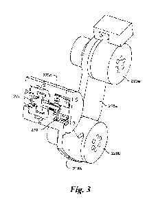
[0066] In particular, referring to Figs. 3 and 4, one or more of the
joints 220a, 220b, 220c
can include at least one brake 270 operatively connected to at least one gear
or gear train 272.
Each brake 270 can be an electro-mechanical or an electro-magnetic fail safe
brake, and each
gear 272 can be a high ratio harmonic gear drive, strain wave, planetary, or
other type gear box.
The gear(s) 272 are not limited to the above type or configuration, as one or
more could be other
types of gears, such as planetary or cycloidal or even direct drive (no
gearing whatsoever). Each
- 10 -
CA 03060440 2019-10-21
WO 2018/195375
PCT/US2018/028480
gear box 272 can reflect or produce the brake rotor inertia to the user (e.g.
surgeon), multiplied
by the square of the gear ratio to provide inertial dampening. This damping
can prevent sudden
dropping of the patient's head, for example, when the joint release mechanism
is engaged or
when one or more of the operator control interfaces are released by the
surgeon or other
healthcare professional. One or more of the joints 220a, 220b, 220c can
include additional
features or components to add in the functionality of the system. For example,
an encoder can be
positioned at or in one or more of the joints 220a, 220b, 220c to aid the
medical team's ability to
return the arm assembly 200 and/or the entire system to a desired or original
position. One or
more counterbalance springs and/or motors can be employed on or in one or more
of the joints
220a, 220b, 220c to provide a gravity assist and/or active positioning.
[0067] In one embodiment, the higher the ratio of the gear box(es)
272, the smaller the
brake(s) 270 can be to accomplish the desired functionality. Furthermore, the
timing of the
release of one or more of the joints 220a, 220b, 220c and/or the ball joint
mechanism 400 could
be staggered such that the weight of the patients head and neck is
progressively transferred from
the device to the operator, allowing the surgeon time to react to any sudden
drop of the patient's
head. One or more torsional or other spring type can be operatively connected
to the joint or
gear(s) 272 that could provide a gravity compensation torque, further reducing
the possibility of
sudden acceleration of the patient's head and neck
[0068] The rotary joints 220a, 220b, 220c and ball joint mechanism
400 can be
configured to lock in any precise, desired head posture and to not drift while
locking. The
brake(s) 270 and/or a motor (described in detail below) of the ball joint
mechanism 400 can lock
quickly (e.g., measured in milliseconds) so that there is no need for the
surgeon or other
healthcare professional to hold the patient's head still for an extended
period of time (which is
required by prior art devices).
[0069] One or more of the batteries 222 can supply power to each brake 270
and/or
motor (described in detail below) of the ball joint mechanism 400. The present
disclosure is not
limited to batteries as the sole power source for these or other electrical
components of the
system, as other well-known power sources can be used. For example, the system
or any portion
thereof could plug directly into the surgical table (supplied with power) or a
wall outlet to get its
power. As described in detail below, one or more operator control interfaces
are operatively
and/or electrically coupled to each brake 270, each motor, and/or each battery
222 or other
- 11 -
CA 03060440 2019-10-21
WO 2018/195375
PCT/US2018/028480
power source. In one embodiment, upon activation of one or more of the
operator control
interfaces, electrical power can be supplied to one or more of the brakes 270
and/or motor(s).
[0070] In one embodiment, one or more of the brakes 270 and motor(s)
are configured to
be "fail safe." Thus, when power is removed from the brakes 270 and/or
motor(s), one or more
of the link arms 218a, 218b and/or the ball joint mechanism 400 can fully lock-
up, which is the
normal state during surgery. When power is applied (via the enable and/or
release buttons
described herein), the brakes 270 and/or motor(s) are free to rotate.
Additional motors and
servos could be added to provide any amount of holding or drive torque. In an
alternative
embodiment, one or more brakes, motors or other components can apply variable
friction to one
or more of the link arms 218a, 218b and/or the ball joint mechanism 400,
thereby slowing
movement of these components.
[0071] The above-described arrangement and features allow one or more
of the joints
220a, 220b, 220c and/or each ball joint mechanism 400 to have an unlocked
state and a locked
state. In the unlocked stated, each joint 220a, 220b, 220c and each ball joint
mechanism 400 can
be freely moveable without any or only negligible resistance. This can allow
for maximum
manipulation or maneuverability of the entire system. In the locked state,
each joint 220a, 220b,
220c and each ball joint mechanism 400 can be fixed, thereby providing maximum
support
and/or stability to the patient. Of course, not all of the joints 220a, 220b,
220c or the ball joint
mechanism 400 are required to be locked or unlocked at the same time. For
example, one or
more of the joints 220a, 220b, 220c and/or ball joint mechanism 400 can be
unlocked, while one
or more of the remaining joints 220a, 220b, 220c or ball joint mechanism 400
can be locked.
Such a configuration allows for some or more finite movement or manipulation
of the system.
[0072] As shown in Figs. 1 and 2, a first mount or quick connection
230 can be located at
or proximate to the proximal end 202 of the arm assembly 200. The first mount
230 can include
a body 260 having a longitudinal axis L (see Fig. 2) that can extend in a
plane defined by the link
arms 218a, 218b. At least a portion of the first mount 230 can be sized,
shaped and/or
configured to fit into and/or be received by a recess or receptacle of a base
(embodiments
described in detail below), for example, that attaches to a surgical table. In
one embodiment, the
first mount 230 can be fixedly or permanently attached to the proximal-most
rotary joint 220c.
The proximal-most link arm 218b can rotate about the first mount 230 as a
result of the
proximal-most rotary joint 220c. A distal end 232 of the first mount 230 can
include a tapered
- 12 -
CA 03060440 2019-10-21
WO 2018/195375
PCT/US2018/028480
portion to facilitate easy insertion into the recess or receptacle. An
opposing proximal end 234
can include a spring-biased tab or button 236. Depression of the button 236
can retract a
projection 238 biased outwardly from the first mount 230, which can facilitate
removal of the
first mount 230 from the recess or receptacle. Opposing sides of the first
mount 230 can include
grooves or cut-outs 239a, 239b designed to mate with or complement portions of
the recess or
receptacle.
[0073] Figs. 5 and 6 show detailed views of one embodiment of the
ball joint mechanism
400 of the presently disclosed technology. The ball joint mechanism 400 can
include at least one
ball joint 410 operatively connected to at least one motor 420, such as a DC
brush motor. The
motor 420 can be operatively connected to one or more of the batteries 220 and
can be activated
by one or more of the operator control interface(s). The ball joint 410 can be
a conventional
three-degree-of-freedom ball joint allowing rotation in all three axes. The
ball joint 410 can
include a ball seat 412 and a swivel ball 414. A rod or pin 416, which can be
threaded, can
extend through at least a portion of each of the ball seat 412 and the swivel
ball 414 and into a
biasing compression spring pack 460. The biasing compression spring pack 460
can be a stack
of spring washers or a spring pack.
[0074] An opening in a bottom of the ball seat 412, which the rod 416
passes through,
can be a slot, restricting motion in one plane and thus creating a two-degree-
of-freedom ball
joint. If the ball joint's restricted plane is coincident with the plane the
three rotary joints enable
motion in, redundancy of motion will be reduced. In one embodiment, because of
this slot that
can restrict motion of the ball joint 410, the ball joint 410 is only able to
make yaw and roll
adjustments. In this embodiment, when the surgeon wants to make a sagittal
plane (i.e., pitch)
adjustment, he/she rotates all three joints 220a, 220b, 220c.
[0075] Through a thrust bearing/bushing interface 440, the lower end
of the rod 416 can
contact or engage, but translate independently of, the upper end of a threaded
shaft 462, such as a
ball screw or lead screw. The lower flange or shoulder of interface 440 can
act as a bushing
because threaded shaft 462 can rotate, but the rod 416 does not. The lower
flange can act as a
thrust bearing limiting motion when the spring pack 460 pushes the rod 416
downwardly. In one
embodiment, a bottom end of the threaded shaft 462 can extend into and engage
a first gear
430a. The first gear 430a can matingly engage a second gear 430b, which in
turn matingly
engages a clutch 430c. The clutch 430c can be a one-way bearing or a Sprag
type clutch. The
- 13 -
CA 03060440 2019-10-21
WO 2018/195375
PCT/US2018/028480
clutch 430c is not limited to the exact location shown in Figs. 5 and 6. For
example, the clutch
430c could be moved from proximate the second gear 430b to proximate the
opposite first gear
430a. A gear reducer 480 can be attached at one end to the clutch 430c and at
an opposing (e.g.,
upper) end to the motor 420.
[0076] The threaded shaft 462 can be or form a portion of a rotatory-to-
linear (or vice
versa) device. In particular, a cylindrical ball screw nut or lead screw nut
444 (see Fig. 6) can be
keyed in the housing 445, enabling the nut 444 to move linearly as the
threaded shaft 462 is
rotated. The ball screw nut 444 can be positioned directly above a bearing.
Rotation of the
threaded shaft 462 in one direction (e.g., clockwise) can drive or move the
ball screw nut 444 at
least slightly upwardly, thereby at least slightly compressing the spring pack
460 and thus
driving the rod 416 at least slightly upwardly. Likewise, downward motion of
the rod 416 (e.g.,
driven by the force of the spring pack 460) can cause the ball screw nut 444
to translate or
otherwise move at least slightly downward. This motion causes the threaded
shaft 462 to "back
drive."
[0077] Linear motion of the ball screw nut 444 can thus push upwardly on
the rod 416.
In order to push the rod 416 upwardly, sufficient motor power is needed to
compress the spring
pack 460. When the motor power is released, the spring pack 460 can push the
ball screw nut
444 back downwardly, thereby causing the screw shaft 462 to rotate. The
purpose of the clutch
430c is to minimize the amount of friction and inertia that must be overcome.
With the clutch
aligned properly, the motor and its gearbox do not need to rotate, which
assures a quick and safe
lock-up of the ball joint 410 of the ball joint mechanism 400.
[0078] In one embodiment, the ball joint mechanism 400 can be biased
to lock the ball
joint 410, thereby preventing movement in either of the two degrees of
freedom. More
particularly, in one embodiment, with the motor 420 in a relaxed or "off'
state, the biasing spring
pack 460 can bias the rod 416 downwardly, thereby moving the swivel ball 414
downwardly and
into engagement with the ball seat 412. In addition, the biasing spring pack
460 can also push
the ball seat 412 into engagement with a cup housing 442 (see Fig. 6) beneath
the ball seat 412
and above the biasing spring pack 462. Such engagement can lock the position
of ball joint 410
and prevent its rotation. This functionality can help to maintain the system
100 in a desired
configuration or position, thereby supporting the patient while the surgeon or
other healthcare
professional performs the medical procedure. In one embodiment, the patient's
head is attached
- 14 -
CA 03060440 2019-10-21
WO 2018/195375
PCT/US2018/028480
(indirectly) to the ball seat 412, so the above-described configuration and
components provide
two frictional surfaces, both generating holding torque, thereby creating a
dual (concentric) ball
joint. The torque is "doubled" because the ball seat 412 is captured and
tightly clamped on both
its inner (e.g., upper) and opposing outer (e.g., lower) ball surfaces.
[0079] When it is desirable to reposition the patient, power can be
supplied to the motor
420, which, in one embodiment, can cause the second gear 430b to rotate via
engagement of the
clutch 430c. Rotation of the second gear 430b will engage the first gear 430a,
thereby causing
rotation of the threaded shaft 462. Rotation (e.g., clockwise when viewed from
beneath the ball
joint mechanism 400) of the threaded shaft 462 can effectuate a change of the
biasing spring
pack 460 that can release the ball joint 410. For example, in one embodiment,
this rotation of the
threaded shaft 462 can cause the ball screw nut 444 and the lower end of the
spring pack 460 to
be moved at least slightly upwardly, thereby at least slightly compressing the
spring pack 460,
which in turn can release or at least reduce tension or a downward force
previously applied to the
rod 416. This can permit the rod 416 to move at least slightly upwardly and
release the ball joint
410 from a clamp created by compression of the swivel ball 414 onto the ball
seat 412 by the rod
416. The clamp can be a double (concentric) surface ball joint clamp.
[0080] When the motor 420 is turned "off' or power is cut to the
motor 420, torque is no
longer applied to the threaded shaft 462. When this occurs, the force of the
compressed spring
pack 460 pushes the ball screw nut 444 at least slightly downwardly. Since the
ball screw nut
444 is keyed, this linear motion causes the threaded shaft 462 to rotate
(i.e., back drive). In this
embodiment, without the clutch 430c, the entire drivetrain, including the
motor 420 would back
drive.
[0081] Thus, in one embodiment, when the motor 420 is engaged,
activated or powered,
the rod 416 can permit the swivel ball 414 of the ball joint 410 to move in
two degrees of
motion, but can prevent the ball joint 410 from moving or rotating in a third
degree of motion.
However, when the motor 420 is not engaged, activated or powered, the rod 416
can prevent any
motion or rotation of the ball joint 410. In an alternative embodiment, as
understood by those
skilled in the art, the drive drain and/or components of the ball joint
mechanism 400 can be
designed such that activation of the motor 420 prevents movement of the ball
joint 410 and
deactivating the motor 420 permits movement of the ball joint 410.
- 15 -
CA 03060440 2019-10-21
WO 2018/195375
PCT/US2018/028480
[0082] In one embodiment, the first and second gears 430a, 430b can
be omitted from the
design. For example, the same or similar functionality could be accomplished
with an "in-line"
design, where the motor 420, the clutch 430c, and the ball screw 462 are all
on the same axis.
Such a design would eliminate the gear set, if that is desirable, but could
double the height of the
ball joint mechanism 400 (which could be acceptable in certain circumstances).
[0083] As shown in Figs. 1, 2 and 16-18, the position of the ball
joint mechanism 400
and/or the ball joint 410 relative to other components of the system 100 can
be advantageous. In
one embodiment, the ball joint 410 can be located or positioned proximate to
the patient's head,
and generally between the patient's head and the arm assembly 200. When
attempting to make
minute changes to the position of the patient's head, it can be beneficial for
the ball joint 410 to
be located proximate to the patient's head, because all rotation of the
patient's head affects the
patient's neck. Specifically, when reorienting the patients head in the
coronal plane (yaw),
rotating the head about a point located close to the neck will minimize
translation of the head in
the coronal plane, thus limiting transverse motion of the cervical vertebra.
This proximity of the
two-degrees of freedom provided by the ball joint 410 allows the surgeon or
other healthcare
professional to make minute or finite changes in the orientation of the
patient's head with
minimal effect on the surgical site. In the prior art, any ball joint is
spaced-apart from the
patient's head, such that all or a majority of any articulating arm is
positioned between the
patient's head and the ball joint. Such an arrangement in the prior art can
limit the effectiveness
and range of coronal plane adjustments.
[0084] In one embodiment, one important feature of the ball joint 410
and/or the ball
joint mechanism 400 is the locking/unlocking function. Locking can be provided
by the failsafe
spring pack 460, which can be similar to spring packs employed in electro-
mechanical brakes,
such as those used on the rotary joints 220a, 220, 220c. Once power to the
motor 420 is
removed, the clutch 430c can allow the ball joint 410 to lock and/or be locked
quickly because
the inertia and friction of the motor 420 does not need to be back driven,
thus enhancing the
safety of the system. The motor 420 can provide the unlocking function by
rotating the ball
screw 462 and compressing the brake(s) 270. Other important features of the
ball joint 410 are
the concentric locking surfaces, essentially doubling the holding torque, and
the pin 416 in the
slot, which reduces it to two degree-of-freedom and thereby eliminating the
sagittal plane
adjustment conflict.
- 16 -
CA 03060440 2019-10-21
WO 2018/195375
PCT/US2018/028480
[0085] Referring to Figs. 1 and 2, the first operator control
interface 300 can include a
body 302 having a first actuator 304 and a second actuator 306. The first and
second actuators
304, 306 can be spaced-apart. The first actuator 304 can be in the form of a
spring-actuated
trigger or tab, which can be depressed and/or engaged by a user when the user
grasps the body
302. The second actuator 306 can be in the form a spring-actuated push button,
which can be
depressed and/or engaged by a user's finger. In operation, when the user
grasps the body 302
tightly, enabling actuator 304, he/she is exerting control of the device and
is likely to have a
strong enough grip to support the weight of the unlocked actuator. In this
position, it can be
most comfortable for the user to depress the second actuator 306 with his or
her thumb. Each of
the first and second actuators 304, 306 of the first operator control
interface 300 can be
operatively and/or electrically connected to the motor 420 of the ball joint
mechanism 400 and/or
the brake(s) 270 of one or more of the joints 220a, 220b, 220c in a manner
requiring BOTH
actuators 304, 306 be enabled in order to free the mechanism. Thus, in one
embodiment, the
surgeon or other healthcare professional can move or reposition the patient
only through exerting
control of the mechanism by engagement of the first actuator 304, then or
subsequently by
triggering the mechanism by engagement of the second actuator 306. In one
embodiment, the
actuators 304, 306 could be engaged simultaneously to produce or permit the
desired movement.
[0086] The first operator control interface 300 is not limited to
inclusion of two separate,
spaced-apart actuators. For example, the first operator control interface 300
could include three
or more actuators, depending upon the desired functionality of the system. An
additional
actuator 307 (see Fig. 1) can be located on an opposite end of the body 302
from the second
actuator 306. The position or location of the additional actuator 307 can
enable a similar
actuation as that described above when the first operator control interface
300 is in a
configuration upside down to that shown in Fig. 1, which can occur during
rotation or flipping of
the patient on certain surgical (e.g., spine) tables.
[0087] As with all components described herein, the first operator
control interface 300 is
not limited to the exact size, configuration and/or positioning shown in the
figures attached
hereto. Although the body 302 is shown as being generally cylindrical and
having a longitudinal
axis that extends generally in the plane defined by the link arms 218a, 218b,
the presently
disclosed technology is not so limited. For example, in an alternative
embodiment, the
- 17 -
CA 03060440 2019-10-21
WO 2018/195375
PCT/US2018/028480
longitudinal axis of the body 302 can extend generally perpendicular to the
plane defined by the
link arms 218a, 218b, and can only include the first actuator 304 at one end
or side thereof
[0088] The body 312 of the first operator control interface 300 can
be spaced-apart from
the ball joint 410 and an attachment mechanism 310 of the first operator
control interface 300.
In particular, the body 312 can be attached to an upper or output side of the
ball joint 410 by a
shaft 312. Thus, the attachment mechanism 310 can be spaced-apart from the
body 302 and be
permanently and/or fixedly attached thereto by a shaft 312. Such a
configuration allows a user
(e.g., surgeon) to move or drive all axes of the system when the brake(s) 270
and the motor 420
are in the released state.
[0089] The attachment mechanism 310 can include one or more features that
permit
permanent or removable attachment to the ball joint mechanism 400, one or more
head supports,
a second operator control interface 332, and/or a third operator control
interface 240 (described
in detail below). For example, a rotatable knob 314 or tightening clamp (see
Fig. 2) can be
configured to move (e.g., open and/or close) vice-like jaws 321a, 321b that
can be configured to
grasp a portion of a head support therebetween. In one embodiment, the grasped
portion of the
head support can snap into place by depression of an interior button 322. If
the jaws 321a, 321b
are not sufficiently tightened by the knob 314 to properly clamp a head
support, the interior
button 322 can function as a safety catch so the head support will not
inadvertently separate from
the attachment mechanism 310. A release button 316 (see Fig. 1) can allow the
head support to
be removed or separated from the attachment mechanism 310. Thus, a second
action (e.g.,
depressing the release button 316) can be necessary to remove the head support
from the
attachment mechanism 310.
[0090] The attachment mechanism 310 can further include a first
receptacle 318 and a
second receptacle 320. A longitudinal axis of the first receptacle 318 can
extend perpendicularly
to a longitudinal axis of the second receptacle 320. The first receptacle 318
can be sized, shaped
and/or configured to receive at least a portion one or more of the head
supports (as described in
detail below), and the second receptacle 320 can be sized, shaped and/or
configured to receive at
least a portion of the third operator control interface 240 (as described in
detail below). Each of
the receptacles 318, 320 can include one or more exposed electrical contacts
(e.g., pogo pins). It
is understood by those skilled in the art that the receptacles 318, 320 are
not limited to be located
on or in the attachment mechanism 310. For example, either or both of the
receptacles 318, 320
- 18 -
CA 03060440 2019-10-21
WO 2018/195375
PCT/US2018/028480
can be formed on or in the ball joint mechanism 400, the body 302 of the first
operator control
interface 300, the distal end 204 of the arm assembly 200 or the first link
arm 218a.
[0091] As shown in Figs. 1, 2 and 16-18, the position of the first
operator control
interface 300 relative to other components of the system can be advantageous.
Particularly
during initial set-up of the system 100 and/or prior to surgery, it can be
beneficial for the first
operator control interface 300 to be located proximate to the upper end of the
ball joint
mechanism 400 and/or the distal end 204 of the arm assembly 200. Such
proximity allows the
surgeon or other healthcare professional to have his/her hand near the free
end of the arm
assembly 200 and make minute or finite changes in the position of the free end
of the arm
assembly 200, thereby facilitating attachment to a variety of attachments,
such as a head support
(embodiments described in detail below).
[0092] Referring to Figs. 7-10 and 16-18, one or more head supports
can be removably
attachable or fixable to one or more portions of the support or apparatus,
generally designed 100,
of the presently disclosed technology. The system or apparatus 100 can include
or be attached to
a variety of different types of head supports depending upon the medical
procedure and/or the
patient's condition. One embodiment of a head support is a head clamp 330
shown in Figs. 7, 17
and 18. The head clamp 330 can be beneficial for long, more intrusive
procedures that require
more precise head control. Generally, head clamps are known in the art.
However, one unique
feature of the head clamp 330 of the presently disclosed technology is the
manner in which it is
removably attachable to a remainder of the system or apparatus.
[0093] In one embodiment, as shown in Fig. 8, an adapter, generally
designated 500, can
permit the head clamp 330 to be removably attachable to the attachment
mechanism 310 of the
first operator control interface 300. The adapter 500 can also be used to
secure or fix the head
clamp to the arm assembly 200 or the remainder of the system 100, such that
the operator is able
.. to selectively position and/or orient the patient's head about any axis. A
first or distal end 504 of
the adapter 500 can be sized, shaped and/or configured to be inserted into at
least a portion of the
head clamp 330. An opposing second or proximal end 502 (e.g., a second mount)
of the adapter
500 can be sized, shaped and/or configured to be inserted into at least a
portion of the second
receptacle 320 of the attachment mechanism 310. More particularly, in one
embodiment, at least
a portion of the second end 502 can be inserted into the second receptacle 320
of the attachment
mechanism 310. In operation of one embodiment of the presently disclosed
technology, the first
- 19 -
CA 03060440 2019-10-21
WO 2018/195375
PCT/US2018/028480
end 504 can be installed on the head clamp 330 before the head clamp 330 is
attached to the
patient. Once the head clamp 330 is installed on the patient, the patient can
be moved or rolled
into position, and then the second end of the adapter 500 can be inserted into
the attachment
mechanism 310 or otherwise attached to the arm assembly 200.
[0094] The adapter 500 can include a wheel 512 that can rotate with respect
to a
remainder and/or a body 508 of the adapter 500. The wheel 512 can be fixedly
attached to the
first end 504, which can include one or more threads on an exterior surface
thereof. The wheel
512 can be configured to be grasped or touched by the surgeon or other
healthcare provider, such
that rotation of the second portion 512 can rotate the first end 504, thereby
moving the first end
.. 504 into or out of engagement with a mating female thread of the head clamp
330. Thus, the
wheel 512 can be rotated to tighten the adapter 500 to the head clamp 330. As
a result, the
second end 502 of the adapter 500 can serve as a quick connection into the
attachment
mechanism 310 (e.g., the second end 502 can latch into position (via the
interior button 322), and
then the second end 502 can be clamped tightly into the attachment mechanism
310). This quick
connection can be beneficial as it can limit the time the surgeon or other
healthcare professional
needs to steady the patient's head while engaging the head clamp 330 to the
first operator control
interface 300.
[0095] A plate 510 or a portion of the body 508 can include a series
of spaced-apart
ridges or teeth 514 that can be sized, shaped and/or configured to
complementarily engage
spaced-apart grooves or teeth of the head clamp 330. The combination of
complementary teeth
can lock or fix the head clamp 330 to the adapter 500, which in turn can be
locked to the
attachment mechanism 310. In one embodiment, the plate 510 can be removably
attachable to
the body 508. In one embodiment, the system 100 can include two or more plates
510, each of
which can have a unique teeth pattern or size. The plates 510 can be
selectively attached to or
removed from the body 510 to accommodate different brands or styles, for
example of head
clamps 330.
[0096] Another embodiment of a head support is a head support plate
332 shown in Figs.
9, 10 and 16. A conventional support mask, helmet, pillow or other device can
be mounted onto
the head support plate 332. The head support plate 332 can be beneficial for
shorter, less
intrusive or invasive procedures that require less head control, or for lumbar
or thoracic spine
procedures where the cervical spine is not compromised. The head support plate
332 can include
- 20 -
CA 03060440 2019-10-21
WO 2018/195375
PCT/US2018/028480
an upper plate 340 spaced-apart from a lower plate 342. The upper plate 340
can include an
Opening 341 therein, and the lower plate 342 can include a mirrored surface or
portion. At least
a portion of the patient's face can be placed in or aligned with the opening
341. The lower plate
342 can move or pivot with respect to the upper plate 340. This configuration
allows a
healthcare professional, such as an anesthesiologist, to easily and quickly
see the patient's face
during the medical procedure. A projection 344 (e.g., a third mount) with one
or more exposed
electrical contacts can extend outwardly from the head support plate 332. At
least a portion of
the projection 344 can be sized, shaped, and/or configured to matingly engage
one or both the
first and second receptacles 318, 320 of the attachment mechanism 310 of the
first operator
control interface 300, such that the electrical contact(s) of the projection
344 can engage the
electrical contact(s) of the first receptacle 318 or the second receptacle
320.
[0097] The head support plate 332 can include or be in the form of
the second operator
control interface. More particularly, the head support plate 332 can include a
first or left handle
334 spaced-apart from a second or right handle 336. In one embodiment, each of
the first and
second handles 336 can be positioned on a bottom side of the upper plate 340,
and can be
engaged when moved or pressed upwardly toward a top surface of the upper plate
340. Each of
the first and second handles 334, 336 of the head support plate 332 can be
operatively and/or
electrically connected to the motor 420 of the ball joint mechanism 400 and/or
brake(s) 270 of
one or more of the joints 220a, 220b, 220c. In one embodiment, each handle
334, 336 can
include an actuator or release trigger 334a, 336a on an inside surface thereof
Such a design can
require the user to wrap his or her fingers completely around each handle 334,
336 before the
actuator 334a, 336a can be exercised, engaged or depressed. In this
embodiment, each of the
first and second handles 334, 336 and the actuators 334a, 336a of the head
plate 332 can be
operatively and/or electrically connected to the motor 420 of the ball joint
mechanism 400 and/or
brake(s) 270 of one or more of the joints 220a, 220b, 220c. One goal of such
an embodiment can
be to require the user to exert control over the system 100 and/or head
support plate 332 before
the brake(s) 270 and ball joint 410 can be released. In one embodiment, it can
be required that
both the left and right triggers 334a, 336a be actuated before the brake(s)
270 is/are released,
thus ensuring the safety of the system 100 and the head support plate 332. In
on embodiment,
the head plate 332 can include a rotatable knob similar in structure and
functionality to that
described below for the third operator control interface.
-21 -
CA 03060440 2019-10-21
WO 2018/195375
PCT/US2018/028480
[0098] Thus, with the patient's head supported on or by the head
support plate 332, the
surgeon or other healthcare professional can selectively move the head support
plate 332 and/or
the patient's head by engagement of one or both of the first and second
handles 334, 336 and/or
the actuators 334a, 336a. The positioning of the first and second handles 334,
336 and/or the
actuators 334a, 336a can be advantageous, as the surgeon or other healthcare
professional can
have his/her hands very close to the patient's head during movement of the
head support plate
332. This gives the surgeon or other healthcare professional increased control
of the movement
of the patient. In addition, the surgeon or other healthcare professional
would not be required to
go behind or beneath the surgical drape to move or reposition the patient.
[0099] Fig. 11 shows a perspective view of a third operator control
interface 240. The
third operator control interface 240 can include one or more spaced-apart
handles 242a, 242b,
which can be coupled to extensions or "horns" 244 that are attached to a
housing 246 (e.g.,
fourth mount). The housing 246 can include one or more exposed electrical
contacts. At least a
portion of the housing 246 can be sized, shaped and/or configured to engage or
be received in
.. one or both of the first and second receptacles 318, 320 of the attachment
mechanism 310 of the
first operator control interface 300, such that the electrical contact(s) of
the housing 246 can
engage the electrical contact(s) of the first receptacle 318 or the second
receptacle 320. A
rotatable knob 248 can be fixed to a shaft 250 that is insertable into and
extendable through at
least a passageway in the housing 246. The knob 248 can allow the surgeon or
other healthcare
professional to tighten, lock or more securely attach the third operator
control interface 240 to
the first operator control interface 300, and/or loosen or prepare to release
the third operator
control interface 240 from the first operator control interface 300.
[00100] Each handle 242a, 242b can include one or more an
actuators 244a, 246a,
244b, 246b. Two or more of the actuators 246a, 246b can be in the form of a
spring-actuated
trigger or tab, which can be depressed and/or engaged by a user's palm when
the user grasps the
handle 242a, 242b, respectively. Two or more of the actuators 244a, 244b can
be in the form a
spring-actuated push button, which can be depressed and/or engaged by a user's
finger. In
operation, when the user grasps the handle 242a, 242b, it can be most
comfortable for the user to
depress the actuators 244a, 244b with his or her thumb. Each of the actuators
244a, 246a, 244b,
246b of the third operator control interface 240 can be operatively and/or
electrically connected
to the motor 420 of the ball joint mechanism 400 and/or brake(s) 270 of one or
more of the joints
- 22 -
CA 03060440 2019-10-21
WO 2018/195375
PCT/US2018/028480
220a, 220b, 220c. It is understood that the actuators 244a, 244b, 246a, 246b
can be coupled to
the joints 220a, 220b, 220c and/or the ball joint mechanism 400 in any
appropriate manner. As a
result of the coupling or connection, the surgeon or other healthcare
professional can move or
reposition the patient through engagement of one or both of the actuators
244a, 246a, 244b,
246b.
[00101] In operation of one embodiment, the handles 242a, 242b
allow accurate
positioning of the patient's head, through movement of the head clamp 230, for
example, when
the joints 220a, 220b, 220c and/or the ball joint mechanism 400 are in an
unlocked state. This
can be accomplished by the surgeon, or other personnel, grasping one or both
of the handles
242a, 242b and actuating the actuators 244a, 244b after actuating the
actuators 246a, 246b, to
place the joints 220a, 220b, 220c and/or the ball joint mechanism 400 in an
unlocked state and
moving the handles 242a, 242b to desired positions. Releasing the actuators
244a, 244b, 246a,
246b can place the joints 220a, 220b, 220c and/or the ball joint mechanism 400
in a locked state
to retain the desired position. This configuration does not permit inadvertent
movement of the
patient's head or when the surgeon does not have a balanced, two-handed, grasp
of the handles
242a, 242b.
[00102] In one embodiment, the surgeon can be required to engage
(e.g., firmly
grip) both handles 242a, 242b before he/she is able to release the brake(s)
270 and/or the joint(s)
220. In this embodiment, an algorithm of the system 100 can require that both
enable buttons
246a, 246b be engaged, depressed or fully depressed before any motion of the
system 100 is
permitted or possible. Then, with a firm grip established, the surgeon can
easily and
ergonomically release one or both trigger buttons 244a, 244b. This will
provide a high level of
safety by assuring the physician is ready and capable to support the weight of
the patient's head.
[00103] Furthermore, the algorithm can allow for three modes of
release. For
example, in one embodiment, if only one trigger button 244a, 244b is actuated
or depressed, the
ball joint 410 can unlock allowing coronal plane and roll motion. If the other
trigger button
244a, 244b is actuated or depressed, one or more of the brakes(s) 270 can be
released, thereby
allowing sagittal plane adjustment. If both trigger buttons 244a, 244b are
released or engaged
together or simultaneously, then all joints (e.g., each brake 270 and the ball
joint 410) can be
released. As soon as any enable or trigger button 244a, 244b is released, all
axes can
immediately lock-up.
- 23 -
CA 03060440 2019-10-21
WO 2018/195375
PCT/US2018/028480
[00104] Referring to Figs. 12-18, the system or apparatus can
include a base to
removably attach the arm assembly 200 to the support apparatus 150. It can be
beneficial if the
arm assembly 200 is able to move with respect to the support apparatus 150 to
provide the
surgeon or other healthcare professional with additional options for moving or
repositioning the
patient. Thus, it can be beneficial that the base of the presently disclosed
technology can move
in two degrees (e.g., in an X direction and in a Y direction) with respect to
the support apparatus
150.
[00105] As shown in Figs. 12, 13 and 16, one embodiment of the
base, generally
designated 600, can include a first body 602 and a second body 604. The first
body 602 can be
configured to contact or attach directly to a portion of the support apparatus
150. The second
body 604 can include a receptacle 606 that can be sized, shaped and/or
configured to receive at
least a portion of the body 260 of the first mount 230. A rotatable knob 608
can be fixed to a
shaft that is insertable into and extendable through at least a passageway in
the second body 604.
The knob 608 can allow the surgeon or other healthcare professional to tighten
or more securely
attach the arm assembly 200 to the base 600, and/or loosen or prepare to
release the arm
assembly 200 from the base 600.
[00106] The second body 604 can be configured to move with
respect to the first
body 602. More particularly, a portion of the second body 604 can include one
or more ball or
roller bearings that can engage and/or ride on a rail 610 of the first body
602. Thus, the second
body 604 can move generally perpendicularly to a longitudinal axis of the
patient and/or a plane
in which the arm assembly 200 extends. A locking tab or handle 612 can be
attached to the
second body 604, and can be movable between a first or locked position and a
second or
unlocked position. In the locked position, the locking tab 612 can engage a
brake mechanism
that grasps at least a portion of the first body 602 (e.g., the rail 610) or
otherwise prevents the
second body 604 from moving with respect to the first body 602. In the
unlocked position, the
brake mechanism is released and/or the locking tab 612 does not interfere with
or can permit the
second body 604 to be moved with respect to the first body 602. In one
embodiment, to move
the second body 604 with respect to the first body 602, the locking tab 612
can be rotated from
the locked position to the unlocked position. The surgeon or other healthcare
professional can
grasp or otherwise touch a portion of the system 100, such as the arm assembly
200, the skull
clamp 330, the steer horns 240 or the prone platform 332 and easily move or
adjust the second
- 24 -
CA 03060440 2019-10-21
WO 2018/195375
PCT/US2018/028480
body 604 laterally. This allows the surgeon place the patient's head exactly
where he/she needs
it. The rail 610 and bearing(s) provide the low friction and rigidity to make
this nearly effortless.
[00107] The first body 602 can be configured to lock onto and/or
move or slide
with respect to the support apparatus 150. In particular, in one embodiment,
opposing lateral
sides of the first body 602 can each include a two-part or two-stage clasp
mechanism. For the
sake of brevity and convenience only, portions of the below description may
focus on the clasp
mechanism on only one of the lateral sides of the first body 602, though it is
understood that the
opposing lateral side can include the mirror structure and functionality. More
particularly, one or
each opposing side of the first body 602 can include a first clasp 614a, 614b
that can include and
be fixed to a pin 616 that extends along a Y axis (e.g., parallel to the
direction in which the
patient extends). As shown in Figs. 13B-F, the pin 616 can engage and/or
extend through a slot
in a housing 628 of the first body 602, which can enable the pin 616 (and thus
the first clasp 614)
to pivot (e.g., rotate) and/or translate (e.g., move linearly) vertically.
[00108] Each first clasp 614a, 614b can include a portion that
extends vertically
downwardly from the pin 616a, 616b and another portion that extends generally
perpendicularly
thereto to extend beneath at least a portion of the support apparatus 150. The
segment of the first
clasp 614 that can be positionable below the support apparatus 150 (e.g., the
"horizontal"
segment of the first clasp 614) can include one or more spaced-apart
compressible friction
members 630. In one embodiment, each compressible friction member 630 can be a
rubber
grommet. Each first clasp 614a, 614b can move between a first, non-engaged
position and a
second, engaged position (see Figs. 12 and 13A-F). One or each opposing side
of the first body
602 can also include second clasps 618a, 618b that can pivot about the pin 616
and can be
positioned in a longitudinal midsection of the first clasp 614a, 614b. Each
second clasp 618a,
618b can move, rotate and/or pivot with respect to the respective first clasp
614a, 614b. Similar
to the first clasps 614a, 614b, each second clasp 618a, 618b can move between
a first, non-
engaged position (see, e.g., Figs. 13B-13D) and a second, engaged position
(see Figs. 12, 13A,
13E and 13F). As shown in Figs. 13D and 13F, each second clasp 618 can include
a cam or cam
surface 632, which can selectively engage a second pin 634 fixed in the
housing 620 and/or a
roller 636 that can surround the second pin 634.
[00109] In one embodiment, when the second clasp 618 is in the second,
engaged
position, the cam surface 632 of the second clasp 618 can act against the
second or fixed pin 634
- 25 -
CA 03060440 2019-10-21
WO 2018/195375
PCT/US2018/028480
and roller 636 (see Fig. 13F), thereby causing the first clasp 614 to move
upwards, forcing the
compressible friction member(s) 630 into engagement with at least a portion of
the support
apparatus 150, such that the base 600 cannot move with respect to the support
apparatus 150
along the Y or longitudinal axis. In operation, the compressible friction
member(s) 630 can be at
least slightly compressed under the force of engagement with the first clasp
614 and the support
apparatus 150, thereby creating a high friction surface. When the second
clasps 618a, 618b are
in the first, non-engaged position (see Figs. 13B-13D), the first clasps 614a,
614b can either be
(i) in the first, non-engaged position such that the base 600 can be separated
from the support
apparatus 150 (see Fig. 13B) or (ii) in the second, engaged position such that
the base 600 can
contact and/or move with respect to the support apparatus 150 along the Y or
longitudinal axis
(see Figs. 13C and 13D). At least a slight clearance gap G (see Figs. 13C)
between the housing
628 or another portion of the first body 602 and the grommet(s) 630, when the
first clasp 614 is
in the downward position but the second clasp 618 is in the upward position,
can enable or allow
for the movement of the base 600 with respect to the support apparatus 150.
Thus, the first
clasps 614a, 614b can function to (i) generally hold the base 600 in place on
the support
apparatus 150, (ii) generally prevent inadvertent movement thereof, and/or
(iii) allow the base
600 to slide or otherwise move with respect to the support apparatus 150
without being separated
from the support apparatus. The second clasps 618a, 618b can function to
generally lock the
base 600 in place on the support apparatus 150.
[00110] In one embodiment, the first clasps 614a, 614b are configured to
rotate
into position under the table support spars and latch into position. A spring-
actuated finger latch
638 can be positioned in a longitudinal midsection of each first clasp 614.
The latch 638 can be
covered or otherwise at least partially concealed by the second clasp 618 when
the second clasp
618 is closed or rotated downwardly (see Figs. 13C-13F), but at least
partially exposed or visible
to the user when second latch 618 is open or rotated upwardly (see Figs. 13A
and 13D). The
latch 638 can be configured to hold the first clasp 614 in the latched, locked
or downward
orientation by engaging a portion of the housing 628 or other portion of the
first body 602. In
one embodiment, as shown in Fig. 13D, the user or surgeon can be required to
engage and/or
rotate the latch 638 (e.g., clockwise in Figs. 13D) to allow the first clasp
614 to reopen. The cam
or cam surface 632 of the second clasp 618 can drive the first clasp 614
upwardly and thereby
enable it to grip at least a portion of one of the spars of the support
apparatus 150. As shown in
- 26 -
CA 03060440 2019-10-21
WO 2018/195375
PCT/US2018/028480
Figs. 13C and 13E, passive or complementary locking tabs 640, 642 on the first
clasp 614 and
the housing 628, respectively, can engage in this position, assuring the that
first clasp 614 cannot
be opened by any jarring impact. This combination allows for three independent
or separate
states of the clasp mechanism: (i) both fully open and unlocked so that the
base 600 can be
placed on the table 150, (ii) first clasps 614a, 614b latched so the base 600
cannot be lifted off
the table 150, yet it is free to translate along the table 150, (iii) the
second clasps 618a, 618b
latched, which drives the first clasps 614a, 614b upwardly to grip the table
150 tightly so the
base 600 is fully constrained.
[00111] As shown in Figs. 14, 15, 17 and 18, a second embodiment
of the base,
generally designated 600', can include many or all of the features of the base
600 of the first
embodiment. The same or similar features of the base 600' of the second
embodiment are shown
with the same reference number as in the first embodiment, but with the
addition of a prime (')
symbol. A description of the same or similar features is omitted herein for
the sake of clarity and
brevity only. One distinguishing feature of the base 600' of the second
embodiment is that the
first body 602' can include three or more components that are configured to
move relative to one
another, thereby adding an additional degree of control or movement to the
system.
[00112] In particular, the first body 602' can include a first
end 620a', a second end
620b', and a mount 624' therebetween. The mount 624' can move (e.g., slide)
with respect to the
first and second ends 620a', 620b'. More particularly, opposing ends of the
mount 624', which
contact or engage the first and second ends 620a, 620b', respectively, can
include one or more
ball or roller bearings that can engage and/or ride on at least a portion of
the first and second
ends 620a', 620b'. Thus, in addition to the horizontal or lateral movement
that the second body
604' can provide, the first body 602' of the second embodiment of the base
600' can provide
longitudinal movement. As shown in Fig. 14, a top surface of each of the first
and second ends
620a', 620b' can include distance markings or a ruler, which can be used to
track the relative
movement of the mount 624' to the first and second ends 620a', 620b' to help
the surgeon or
other healthcare professional position or reposition the patient.
[00113] At least one or two or more locking levers or handles
626a', 626b' can be
attached to the mount 624', and can be movable (e.g., rotatable) between a
first or locked
position and a second or unlocked position. In the locked position, each
locking lever 626a',
626b' can grasp at least a portion of the first and second ends 620a', 620b',
respectively, or
- 27 -
CA 03060440 2019-10-21
WO 2018/195375
PCT/US2018/028480
otherwise prevent the mount 624' from moving with respect to the first and
second ends 620a',
620b'. In the unlocked position, each locking lever 626a', 626b' does not
interfere with or can
permit the mount 624 each locking lever 626a', 626b' to be moved with respect
to the first and
second ends 620a', 620b'. The above-described longitudinal adjustment provided
by the base
600' has many benefits. For example, this design can provide easy adjustments
during patient
set-up to connect the arm assembly 200 to the skull clamp 330 rather than
releasing the second
clasps 618a', 618b' and sliding the entire unit. This design can provide
increased range of motion
during intraoperative adjustments; the low friction allows user to guide the
patients head rather
than having to push or move the base 600' and/or the first body 602'. This
design can provide
static traction; the surgeon can release the levers 626a', 626b', pull the
unit and/or the second
body 604' longitudinally and apply a certain amount of traction to distend the
neck of the patient.
This design can provide active traction; the surgeon can release levers 626a',
626b' and apply a
weight bag via pulleys (for example) to the base 600' and/or the second body
604' and apply a
constant force traction.
[00114] Referring to Figs. 17 and 18, in one embodiment, instead of the arm
assembly 200 being directly attached to the base 600, 600', a tower 700 can be
positioned
between the arm assembly 200 and the base 600, 600'. More particularly, the
first mount 230 of
the arm assembly 200 can be inserted into a receptacle of the tower 700, and a
projection (e.g.,
fifth mount) of the tower 700 can be inserted at least partially or completely
into the receptacle
606, 606' of the base 600, 600'. The tower 700 can permit the proximal end 202
of the arm
assembly 200 to be vertically raised or lowered (e.g., along the Z axis) with
respect to the base
600, 600'. A rotatable crank 702 can be located at a top or bottom of the
tower 700, which can
allow the surgeon or other healthcare professional to selectively raise or
lower the proximal end
202 of the arm assembly through any of a variety of different mechanisms
(e.g., lead screw or
rack and pinion system). The tower 700 can provide move vertical movement or
range to the
system 100. For example, the tower 700 can provide a "stroke" of six to seven
inches.
[00115] The term "surgical table" is broadly defined herein to
include any
structure to which the system 100 can be attached to and supported by during a
medical
procedure. Any type, style, size and/or configuration of surgical table can be
used as part of or
attached to the system 100 of the presently disclosed technology. For example,
surgical tables
disclosed in U.S. Published Application No. 2016/0228315 can be used in
combination with the
- 28 -
CA 03060440 2019-10-21
WO 2018/195375
PCT/US2018/028480
presently disclosed technology. The system 100 is not limited to be used with
a surgical table in
the form of an H-frame with rectangular supports. Further, various patient
support attachments
and other devices can be used in combination with the invention.
[00116] In operation, at least a portion of one, two or each of
the first operator
control interface 300, the second operator control interface 332, and the
third operator control
interface 240 can be engaged or manipulated by the surgeon or other healthcare
professional to
provide or create the desired inter-operative movement of the patient. In one
embodiment, one
or more of the actuators or buttons of one or more of the first operator
control interface 300, the
second operator control interface 332, and the third operator control
interface 240 can be
engaged to progressively or sequentially release, unlock or lock the ball
joint 410 and/or the
joints 220a, 220b, 220c. In such an embodiment, one goal can be to
sequentially release the
brake(s) 270, thereby providing (i) additional movement of the system 100 upon
release of each
brake 270 and giving the surgeon more control, and/or (ii) slow or predictable
transfer of weight
from the system 100 to the surgeon and/or other healthcare professional. To
perform a different
.. operation in the same embodiment, or in a different embodiment, one or more
of the actuators or
buttons of one or more of the first operator control interface 300, the second
operator control
interface 332, and the third operator control interface 240 can be engaged to
release, unlock or
lock in parallel or simultaneously. Of course, the actuators or buttons could
be engaged in any
combination of in parallel or in series. For example, in one embodiment,
movement (of at least
one of the ball joint 410 and/or the joints 220a, 220c, 220c) may not begin
until two actuators
(e.g., the first actuator 304 and the second actuator 306 of the first
operator control interface 300)
are depressed or engaged (e.g., either in series or in parallel). In another
embodiment,
engagement of one of the actuators can allow the system 100 to move in one
plane (e.g., the
sagittal plane); engagement of a second one of the actuators can release the
ball joint 410,
thereby allowing for both roll and yawl movement; engagement of both actuators
can permit all
degrees of motion or movement. In one embodiment, upon engagement of one or
each of the
actuators or buttons, the system 100 can configured to perform (e.g., begin)
the desired
movement or motion within approximately 300 milliseconds, which is a typical
human reaction
time. This is a significant improvement over the prior art, and ensures that
patient positioning
and repositioning can be done quickly and with relative each by the medical
staff.
- 29 -
CA 03060440 2019-10-21
WO 2018/195375
PCT/US2018/028480
[00117] As shown in Figs. 16-18, the location and/or position of
each of the first
operator control interface 300, the second operator control interface 332, and
the third operator
control interface 240 can be beneficial. In one embodiment, the position of
each of the operator
control interfaces 300, 332, 240 can allow the surgeon or other healthcare
professional (i) to
move and/or control the patient's head through the drapes (ii) while scrubbed
in, and (iii) while
maintaining sight of the surgical site and without relying on assistance from
any other person.
Each of the operator control interfaces 300, 332, 240 can be accessible from
above the patient
and/or are exposed above the patient.
[00118] In one embodiment, as shown in Figs. 19 and 20, the
system 100 is
configured to complement and/or can include a surgical drape 900. The drape
900 can be
designed to cover at least a portion of, the entirety of, and/or interface
with not only to the
patient, but also to at least some or all of the operator control interfaces
300, 332, 240 of the
system 100. In one embodiment, the drape 900 can allow a sterile surgeon or
other healthcare
professional (i) to directly move, adjust and/or control the position of the
third operator control
interface 240 and thus adjust the position and orientation of the patient's
head through the drapes
(ii) while scrubbed in (i.e., while remaining completely sterile), and/or
(iii) while maintaining
sight of the surgical site, without disturbing the drape/patient interface at
the surgical site, and
without relying on assistance from any other person.
[00119] Such inter-operative adjustment cannot be done with any
prior art system.
In contrast, when attempting to move a patient's head in a sterile manner
during surgery in prior
art systems, one member of the medical team is required to go beneath the
surgical table and/or
the patient's head, and then rescrub after the adjustment is made. The
surgical site remains
sterile during this adjustment in prior art systems, but the procedure is can
be clumsy,
challenging, and time-consuming.
[00120] In one embodiment, during a medical procedure, the third operator
control
interface 240 including the actuators 244a, 244, 246a, 246b can be accessible
from above the
patient and/or are exposed above the patient and accessible through the drape
900. The drape
900 can be entirely transparent. Alternatively, the surgical drape can be
primarily opaque and
include one or more spaced-apart transparent windows or pockets 902 to allow
the third operator
control interface 240 to be identified, grasped and/or engaged through the
draft 900 by the user
or surgeon. Thus, the drape 900 can be contoured to allow the third operator
control interface
- 30 -
CA 03060440 2019-10-21
WO 2018/195375
PCT/US2018/028480
240 to be identified and easily gripped through the drape 900 by the user,
without disturbing the
drape 900 at the location of the surgical site. A transparent sock can be
applied to at least a
portion of the third operator control interface 240 prior to the application
of the drape 900 to
provide a second transparent protective barrier. Other embodiments of the
drape 900 can
provide interfaces or pockets to the first and second operator control
interfaces 300, 322 and/or
other actuators or controls 612, 626a', 626b' of the system 100 in similar
manners.
[00121] The electrical nature of the system 100 can also provide
feedback when
movement of any portion of the system 100 occurs. For example, upon engagement
of one of
the actuators and movement of at least one of the joints 220, 220b, 220c, the
system 100 can emit
a tone, display an image or word on a monitor, illuminate a light or series of
lights, or the like.
The feedback can also be in the form of data, such as the speed, angle, range,
displacement, etc.
of the movement. Such feedback can be helpful to a surgeon or other healthcare
professional in
any of a variety of ways, such as for teaching others how to perform surgery,
for repeating
successful surgeries, and/or for legal matters, such as malpractice claims.
[00122] Now referring to Fig. 21, which illustrates a top side of another
embodiment of a
surgical drape used with the systems or apparatuses disclosed herein. The top
side of the surgical
drape 2100 includes a drape 2101, a window 2102, one or more covers 2103A,
2103B, a surgical
opening 2104, one or more fastener components 2105A-D, and one or more
markings 2106,
2107 on a proximal end 2108 and a distal end 2109 of the drape 2101.
[00123] The drape embodiment 2101, as illustrated in Fig. 21 is generally
rectangular in
shape with a certain length and width. The proximal end 2108 and the distal
end 2109 of the
drape 2101 may be of the same width; however, a center portion of the drape
2101 may include a
width that is greater than width of the proximal end 2108 and the distal end
2109 of the drape
2101.
[00124] A window 2102 may be included in, and visible on, the top side 2100
of the drape
2101. The window 2102 is transparent and as such acts as a viewing window for
a physician to
see through and observe activity on the opposite side of the drape 2101. The
window 2102 may
not be a hole or opening for passing through objects from the top side 2100 to
the bottom side
2200 of the drape 2101, but rather may be made of a substantially transparent
material. The
window 2102 may be rectangular in shape and is positioned closer to the
proximal end 2108 of
the drape 2101. The window 2102 together with the rest of the drape 2100 acts
like a sterile
- 31 -
CA 03060440 2019-10-21
WO 2018/195375
PCT/US2018/028480
barrier between the top side 2100 and an opposite bottom side 2200 of the
drape 2101. One
skilled in the art would appreciate that one window 2102 is illustrated in
Fig. 21; however,
multiple windows with different sizes and configurations may be incorporated
in the drape 2100.
[00125] In certain embodiments, one or more covers 2103A, 2103B may be
included on
the top side of the drape 2101. As shown in Fig. 21, the top side of the drape
2101 includes a
right side cover 2103A and a left side cover 2103B. These covers are distal to
the window 2102
and extend upwardly in a substantially perpendicular fashion from the top side
of the drape 2101.
The right side cover 2103A and the left side cover 2103B may be transparent,
and may be made
of a polyethylene material, or any other flexible material. The right side
cover 2103A includes a
cover opening 2203 and the left side cover 2103B includes another different
cover opening 2202,
as illustrated in Fig. 22 and further discussed below. The cover opening 2202
allows passage of
one handle, for example handle 242b as shown in Fig. 11, such that the handle
242b is
surrounded by cover 2103A once placed therein, and ready to be engaged by the
physician from
the top side of the drape 2101. Whereas, the opening 2203 allows passage of a
different second
handle, for example handle 242a as shown in Fig. 11, such that the handle 242a
is surrounded by
the cover 2103B once placed therein, and ready to be engaged by the physician
from the top side
of the drape 2101.
[00126] A surgical opening 2104 may be included through the drape
2101. The surgical
opening 2104 is discussed in conjunction with reference to Fig. 23B
represented as 2300B. The
surgical opening 2104 is positioned distal to the one or more covers 2103A,
2103B such that the
one or more covers 2103A, 2103B are positioned in between the window 2102 and
the surgical
opening 2104 as shown in Fig. 21. The surgical opening 2104 may be
substantially rectangular in
shape, and may include two segments or sections. The first segment or section
consists of a
surgical opening or passage through which devices may pass through from the
top side 2100 of
the drape 2101 to the bottom side 2200 of the drape 2101. The surgical opening
allows access to
a surgical site such as an incision made on a patient. The incision may be
made for example on a
neck or upper back region of the patient; however, example embodiments
disclosed herein are
not limited to these regions. The surgical opening 2104 may also be extendable
and include a
second surgical opening segment or section 2104-1, which may be represented as
dotted lines as
shown in Fig. 23B, such that removal of the second surgical opening segment or
section 2104-1
can extend the surgical opening between the first section and second surgical
opening segment or
- 32 -
CA 03060440 2019-10-21
WO 2018/195375
PCT/US2018/028480
section 2104-1. For example, if the physician desires an enlarged surgical
opening in the surgical
opening 2104 region for purposes of increasing flexibility in the work space,
enlarging the
surgical site, or introducing additional objects there through from the top
side 2100 of the drape
2101 to the bottom side 2200 of the drape 2101, the physician may simply
remove the second
surgical opening segment or section 2104-1 of the drape 2101. Thereby,
enlarging the surgical
opening 2104. The removal of the second surgical opening segment or section
2104-1 may be
accomplished using scissors as shown in Figs. 21 and 23B, or alternatively
other similar means
that would be appreciated by one skilled in the art.
[00127] In one embodiment, the distance between the surgical opening
2104 and the
window 2102 may be spaced apart by approximately fourteen (14) inches or more.
One skilled in
the art would appreciate to optimize the distance between the surgical opening
2104 and the
window 2102 such that during a surgical procedure a patient's head may be able
to move
rotationally within range of +/- 30 degrees without displacing the fabric of
the drape 2101 or
causing it to tear especially around the regions of the window 2102 and the
one or more covers
2103A, 2103B.
[00128] Still referring to Fig. 21, in certain embodiments, fastener
components 2105A-D
may be positioned on the top side of the surgical drape 2101. The fastener
components 2105A-D
are positioned on the distal end 2109 of the drape 2101 and proximate to the
surgical opening
2104. The fastener components 2105A-D hold the objects in place, including
objects that may
pass through the surgical opening 2104. The objects may include surgical
instruments or surgical
tools that are required for a surgical procedure. These surgical instruments
or surgical tools may
include, for example, including but not limited to, suction devices and/or
mechanical devices like
electric knives or ultrasound probes. The fastener components 2105A-D may
secure portions of
those objects, for example, tubes or wires. In some embodiments, the fastener
components
2105A-D may be, for example, selected from the group comprising hook and loop
straps, e.g.
Velcro straps, clips or clamps. Although four fastener components 2105A-D are
shown in Fig.
21, one skilled in the art would appreciate that additional fasteners, and
addition types of
fasteners, may be incorporated as desired. For example, additional fasteners
may be incorporated
along the window 2102 or one or more covers 2103A, 2103B; and their
orientation on the top
surface 2100 may be adjusted as desired.
- 33 -
CA 03060440 2019-10-21
WO 2018/195375
PCT/US2018/028480
[00129] In certain embodiments, one or more markings 2106, 2107 may be
included on
the top side 2100 of the drape 2101. However, these one or more markings 2106,
2107 may be
included on the bottom side 2200 of the drape 2101 as well. For example,
marking 2106 may be
included on the proximal end 2108 of the drape 2101 and another marking 2107
may be included
on the distal end 2109 of the drape 2101. These markings are shown in greater
detail Fig. 34. As
such, referring to Fig. 21 in conjunction with Fig. 34, the markings 2106,
2107 may represent a
hand symbol that is holding the drape 2101 and the direction of arrows which
instruct a
physician or user to pull the drape 2101 in a certain direction during
deployment of the drape.
For example, marking 2106 illustrates direction of arrows in one direction and
marking 2107
illustrates direction of arrows in an opposite direction to the arrows shown
in marking 2106.
These markings 2106, 2107 may instruct the physician how to unfold the drape
2101 once taken
out of its packaging.
[00130] Next, referring to Fig. 22, a bottom side of the drape 2200 is
illustrated. In various
embodiments, the bottom side of the drape 2200 may include window 2102,
additional window
material 2301, cover openings 2202, 2203 and adhesive component such as tape
2204 along with
markings 2205.
[00131] The aforementioned features may be illustrated and discussed
in conjunction with
Figs. 23, 23A, 23B and 23C. Fig. 23 depicts the top side of the surgical
drape, illustrating a
transparent window and an extendable opening positioned on the top side of the
surgical drape
2101 is shown. This representation of the top side 2100 of the drape 2101
illustrates the window
2102 along with additional window material 2301, and the surgical opening 2104
along with
markings 2205 on bottom side 2200 of the drape 2101.
[00132] In certain embodiments, the window 2102 will be described in
conjunction with
Fig. 23A, which is shown from the perspective of the top side 2100 of the
drape 2101. The
window 2102 is placed on the bottom side of the drape 2200. In certain
embodiments, the
window 2102 is slightly greater in width and length than that of the opening
in the drape as
shown in Fig. 23A, such that the outline of the additional window material
2301 is indicated.
Also, the cover flanges 2302 are greater in diameter than the diameter of the
holes 2202, 2203.
The window 2102 and the cover flanges 2302 may be bonded to the bottom side of
the drape
2200 using a method selected from pressure sensitive adhesives, heat seal
adhesives, ultrasonic
sealant, and combinations of any thereof. Thereby, securing the window 2102
and the cover
- 34 -
CA 03060440 2019-10-21
WO 2018/195375
PCT/US2018/028480
flanges 2302 on the bottom side 2200 of the drape 2101. Such securing
mechanism is especially
important to prevent a tear or rip in the drape 2101, especially around
regions of the window
2102 and one or more covers 2103A, 2103B when the drape 2101 is being used for
a procedure.
One skilled in the art would appreciate that the additional window material
2301 and the covers
2103A, 2103B may be attached to the drape 2101 using other methods known in
the art.
[00133] The openings 2202, 2203, as discussed above under Fig. 21,
allow passage of one
or more handles there through such that they can be engaged by a physician
from the top side of
the device. For example, handles 242a, 242b, as shown in Fig. 11, may pass
through from the
bottom side of the drape into the openings 2203, 2203 such that the handles
242a, 242b are
securely positioned in the one or more covers 2103A, 2103B for physician's
use.
[00134] In certain embodiments, the adhesive component such as tape
2204 and markings
2205 will be described in greater detail in conjunction with Fig. 23C. The
tape 2204 and
markings 2205 are positioned on the bottom side of the drape 2101 surrounding
the surgical
opening 2104 and the second surgical opening section 2104-1, and distal to the
window 2102. As
shown in greater detail in Fig. 23C, the tape 2204 may include longitudinal
strips 2304, 2305,
2308, 2309 and horizontal strips 2303, 2306 and 2307. These longitudinal and
horizontal strips
are positioned on the bottom side 2200 of the drape 2101 surrounding the
surgical opening 2104
and second surgical opening section 2104-1 as shown in Fig. 23B. The
longitudinal strips 2304,
2305, 2308, 2309 and horizontal strips 2303, 2306 and 2307 may be made
adhesive by removing
an outer protective covering layer, or liner. The longitudinal strips 2305 and
2308 may constitute
two different strips such that they are not connected at the intersection
where they meet the
horizontal strip 2306. Similarly, horizontal strips 2304 and 2309 may
constitute two different
strips such that they are not connected at the intersection where they meet
the horizontal strip
2306.
[00135] Further, the longitudinal strips 2304, 2305 and the horizontal
strips 2303, 2306
may be selectively made adhesive, while the longitudinal strips 2308, 2309 and
horizontal strips
2306, 2307 may not be made adhesive by having the outer covering removed. For
example, if the
physician wants to work with a smaller surgical opening 2104, the physician
may not remove the
outer coverings of longitudinal strips 2308 and 2309 and horizontal strip
2307. Instead, the
physician may limit the removal of outer covering of only the longitudinal
strips 2304, 2305 and
the horizontal strips 2303 and 2306. However, if the physician wants to
increase the surgical
- 35 -
CA 03060440 2019-10-21
WO 2018/195375
PCT/US2018/028480
opening 2104 to include the second surgical opening section 2104-1 to increase
the workspace,
he/she may remove the second surgical opening section 2104-1 as discussed
above with respect
to Fig. 21 and 23B, and additionally remove the outer covering over the
longitudinal strips 2308
and 2309 and horizontal strip 2307. Thereby, making the longitudinal strips
2308, 2309, and
horizontal strip 2307 adhesive and allowing the physician to secure them on
the patient. In this
embodiment, horizontal strip 2306 may be removed during the cutting or removal
of the second
surgical opening section 2104-1. As such the longitudinal and horizontal
strips may be
selectively releasable as desired by the physician.
[00136] Additionally, in certain embodiments, the longitudinal and
horizontal strips may
include respective pull tabs. To create the pull tab, the adhesive underneath
the horizontal or
longitudinal strip may not extend to the edge of the strip, thereby allowing
an easier grip on the
pull tab. For example, strips 2304, 2305, 2308, 2309 may include respective
pull tabs 2305-1,
2305-2, 2305-3 and 2305-4, as shown in Fig. 23C. Additional pull tabs (not
shown) may also be
included on the ends of the horizontal strips 2303, 2306, 2307. These
respective pull tabs are
.. used for engaging or holding on to the longitudinal and horizontal strips.
In certain embodiments,
the respective pull tabs 2305-1, 2305-2, 2305-3 and 2305-4 may or may not be
adhesive as they
assist the user to engage the respective pull tabs in order to remove an outer
covering from the
respective longitudinal and horizontal strips in order to uncover or expose
the underlying
adhesive surface.
[00137] Lastly, with respect to markings 2205, as shown in Fig. 22, 23C and
also in Fig.
34, in certain embodiments they may represent the orientation of the patient
that should be
observed with respect to placing the drape 2201 on the patient. For example,
as shown in
markings 2205, which depicts a patient, for example, has its head facing in
the proximal end
2108 and feet facing in the distal end 2109. Such marking 2205 allows the
physician to orient the
drape 2201 accordingly during the surgical procedure with respect to the
patient such that he/she
is able to view the procedure through the window 2102 and engage the handles
242a, 242b as
they pass through one or more covers 2103A, 2103B, and access the surgical
site on the patient
through surgical opening 2104. One skilled in the art would appreciate that
the markings 2205
disclosed herein are not limited to such representation, and similar
representations maybe
undertaken.
- 36 -
CA 03060440 2019-10-21
WO 2018/195375
PCT/US2018/028480
[00138] Next, with respect to Figs. 24 a side view of an embodiment
the drape 2101 is
shown, wherein one cover 2103B is visible along with two of the adhesive
components 2105C,
2105D.
[00139] Illustrating one embodiment of the cover 2103B in greater
detail is an exploded
view shown in Fig. 24A. The cover 2103B includes a first segment that extends
above the top
surface 2100 of the drape 2101 as shown in Fig. 24A. A second segment includes
a flange 2403
of the cover 2103B. The flange 2403 of the cover 2103B is below the top
surface of the drape
2101. Further, this embodiment may include one or more adhesive components
2402. These
adhesive components 2402 being a single sided tape spaced apart from the
flange 2403. The
cover 2103B illustrated in Fig. 24A is not drawn to scale, and the length of
drape 2101 may be
longer than the flange 2403, and length of the one or more adhesive components
2402 may be
longer than the length of the flange 2403 but shorter than the length of the
drape 2101. The
structural components described herein with respect to cover 2103B also
similarly apply to the
other cover 2103A. In this embodiment, the flange 2403 may be bonded to the
bottom surface
2200 of the drape 2101 by pressure sensitive adhesives, heat sensitive
adhesives, ultrasonic
sealant, and any combinations thereof. The flange 2403 may be bonded between
the bottom side
2200 of the drape 2101 and optionally a tape 2402 on the opposite side of the
flange 2403. The
tape 2402 may overlap the flange 2403 onto the bottom side 2200 of the drape
2101.
[00140] Next with respect to Figs. 25 and 26, a folding embodiment of
drape 2101 is
shown. Fig. 25 illustrates the drape 2101 positioned flat on a surface
extending from the
proximal end 2108 to the distal end 2109 with the bottom surface 2200 of the
drape 2101 facing
the physician. The dotted lines represented in Fig. 25 represented the
accordion style fold that is
undertaken to wrap or fold the drape 2101. Fig. 26 is a side view of the drape
2101 as shown in
Fig. 25 as it is folded inward from either ends towards the center, or as it
is being unfolded.
[00141] Now, disclosure with respect to folding and packaging of certain
embodiments of
the drape 2101 will be discussed with reference to Figs. 24-32. Fig. 27
represents a side view
2700 of the drape 2101 as it is folded inward. With respect to folding the
drape 2101 the
physician, user or technician may start from the proximal end 2108 and the
distal end 2109 of the
drape 2101 as the bottom side 2200 of the drape 2101 is facing the user as
shown in Fig. 25. The
user may fold inward proximal most end on the proximal end and distal most end
on the distal
end of the drape 2101 by having such ends face inward. The user may fold the
proximal most
- 37 -
CA 03060440 2019-10-21
WO 2018/195375
PCT/US2018/028480
end and the distal most end simultaneously or independently of each other.
When folding the
proximal most end and the distal most end, the user may undertake an accordion
style fold, as
shown in Fig. 26, such that such ends are parallel along a surface of the
drape 2101. The
proximal most end is folded inward in accordion style until the proximal end
2108 reaches a
center of the drape as shown in Fig. 27. And, the distal most end is folded
inward in accordion
style until the distal end 2109 reaches the center of the drape as shown in
Fig. 27.
[00142] By having the proximal end 2108 and distal end 2109 folded in
an accordion style
until they reach the center of the drape 2101, a stack of the drape 2101 is
obtained with a head-
end stack and a foot-end stack as shown in Fig. 28. The illustration shown in
Fig. 28 is a partially
folded configuration 2800, wherein a gap is maintained along the orthogonal
axis of bottom
surface of the drape 2101 between the head-end stack and the foot-end stack.
Fig. 29 illustrates
another cross-sectional view 2900 of the partially folded configuration 2800
as shown in Fig. 28.
In particular, Fig. 29 illustrates an orthogonal view showing the partially
folded configuration
2800 having additional folds with the seam oriented medially. Each lateral
side stack is folded
several times medially until the configuration 2900, shown in Fig. 29, is
achieved.
[00143] After achieving such partial fold configuration 2900, each
lateral drape stack is
folded one more time along the medial axis of the bottom surface of the drape
2101. As shown in
in Fig. 30, one embodiment of the complete and final fold configuration 3000
is shown, wherein
each lateral side stack is folded along the medial axis of the bottom surface
of the drape 2101.
Thereby, resulting in a compact configuration of the drape 2101 for purposes
of easy packaging,
shipping and handling.
[00144] With respect to Fig. 31, a top view of the surgical drape 2101
as folded in
orthogonal fashion as shown in Fig. 30 is illustrated. After the surgical
drape 2101 achieves the
final fold configuration 3000, it is placed in a package 3101 such that from
the top view 3100 of
the package 3101, a user can see the marking 2205, which aids the user in
orienting the drape
2101.
[00145] With respect to Fig. 32, a side view of the package 3101 is
shown with a product
label or instructions for use 3202 on the side of the package 3101. As such, a
manufacturer or
maker of the drape may package the drape 2101 in a package 3101 that fits the
drape 2101 in its
final fold configuration 3000.
- 38 -
CA 03060440 2019-10-21
WO 2018/195375
PCT/US2018/028480
[00146] Now, the use of an embodiment of the drape 2101 for a surgical
procedure, for
example, will be described. A physician, a user or a technician may take out
the drape 2101 from
the package 3101 after reading the instructions 3202 on the package 3101. The
drape 2101 may
include a further protective wrapping which would need to be removed before
using the drape
2101. The drape 2101, after removal from the package 3101, will be in the
final folded
configuration 3000 as shown in Fig. 30; and the physician will be able to view
the marking 2205
from a top view as shown in Fig. 31, which will aid the physician to orient
the drape 2101 with
respect to the patient. Being in book-like fashion would allow the user to
easily handle and
maneuver the drape 2101 out of the package 3101. Next, the user or physician
will align the
surgical opening 2104 shown in Figs. 21 and 23B over a surgical site and
position the drape 2101
around the surgical site. Thereafter, the user may remove outer protective
covering from the
longitudinal strips 2304, 2305 and the horizontal strips 2303, 2306 such that
the underlying
adhesive layer is exposed and ready for use. The user may also remove a
release paper covering
a top side or a bottom side of window 2102.
[00147] After orienting the drape 2101 relative to the markings 2205, the
user may place
the longitudinal strips 2304, 2305 and the horizontal strips 2303, 2306 around
an incision site or
the site of interest such that the surgical opening 2104 on the top side 2100
of the drape 2101 is
around the incision site. Thereby, allowing the physician or user to view and
access the incision
site.
[00148] Next, the user will unfold the drape 2101 along orthogonal and
parallel axis of the
drape 2101. In other words, resulting in having the drape 2101 unfold that
would result in
configuration of the drape 2101 shown in Figs. 27, 28 and 29. After the drape
2101 is in this
partially unfolded configuration, the user will identify markings 2106, 2107
on top surface 2100
of the drape 2101. Identifying such markings 2106, 2107, would indicate to the
user to pull the
proximal end 2108 and the distal end 2109 to patient's foot-end and head-end
of the table on
which the patient is placed. Thereby, allowing the drape 2101 to be entirely
unfolded and is flat
on a surface as shown in Fig. 25.
[00149] If the user or physician determines that the surgical opening
2104 needs to be
widened or made bigger in order to increase the working space or allow
additional objects to
pass there through, the user or physician may remove the second surgical
opening section 2401-1
as shown in Fig. 23B. By removing the second surgical opening section 2401-1
the surgical
- 39 -
CA 03060440 2019-10-21
WO 2018/195375
PCT/US2018/028480
opening 2104 can be made bigger such that working space for the physician is
increased.
Thereby, the user may enlarge the incision site or introduce additional
objects through the
opening.
[00150] After the bottom side 2200 of the drape 2101 is in place and
the surgical opening
2104 in the correct position, the user may introduce handles 241a, 241b from
the bottom side
2200 of the drape 2101 and have the handles 241a, 241b pass through the
openings 2202, 2203
such that the handles 241a, 241b are placed in the respective covers 2103A,
2103B. Once the
handles 241a, 241b are in position in the respective covers 2103A, 2103B, the
physician may
engage with the handles 241a, 241b and accordingly maneuver a patient's head
or alternatively
perform the desired surgical procedures as he/she views through the window
2102. Lastly, the
user may engage objects such as surgical instruments or tools with the
fastener components
2105A-D such that such objects are securely positioned in place for use during
a procedure.
[00151] It will be appreciated by those skilled in the art that
changes could be made to the
embodiments described above without departing from the broad inventive concept
thereof For
example, various mechanical and electrical connection elements and actuators
can be used to
achieve the disclosed function. It is understood, therefore, that this
invention is not limited to the
particular embodiments disclosed, but it is intended to cover modifications
within the spirit and
scope of the present invention as defined by the appended claims.
- 40 -