Note : Les descriptions sont présentées dans la langue officielle dans laquelle elles ont été soumises.
CA 03060655 2019-10-21
W02018/193325
PCT/IB2018/052065
1
Oil circuit, oil-free compressor provided with such oil
circuit and a method to control lubrication and/or cooling
of such oil-free compressor via such oil circuit
The present invention relates to an oil circuit, an oil-free
compressor provided with such oil circuit and a method to
control lubrication and/or cooling of such oil-free
compressor via such oil circuit.
More specifically, the invention is intended to provide an
improved oil circuit and an improved method to control
lubrication and/or cooling of an oil-free compressor
comprising a motor with a variable rpm or speed, i.e. with
a variable speed drive (VSD) control, via this improved oil
circuit.
It is known that an oil circuit is used to lubricate and
cool components in such a motor.
These components are for example, but not limited to,
bearings and gears of the motor.
At high motor rpms these bearings and gears need a precisely
dosed oil lubrication: neither too much oil, which may lead
to hydraulic losses and even overheating; nor too little
oil, which may result in excessive friction and overheating.
Therefore, oil jet lubrication is applied, whereby oil is
targeted precisely to a location where the oil is needed by
means of nozzles with a very precise configuration.
CA 03060655 2019-10-21
W02018/193325
PCT/IB2018/052065
2
This location may be a raceway of the bearings or the
location where teeth of the gears engage with each other.
The oil in the oil circuit needs to be cooled, in order to
avoid overheating of the oil in the oil circuit and
concomitant changes in lubricating properties of the oil.
The oil circuit which provides the nozzles with filtered and
cooled oil at a preset pressure level, typically comprise an
oil reservoir, a rotary oil pump, an oil cooler, an oil
filter, and connecting pipes, which may be integrated in
other components of the oil-free compressor. Furthermore,
there are often minimum pressure valves, bypass pipes, oil
pressure sensors and oil temperature sensors.
Traditionally an oil circuit for such an oil-free compressor
is arranged as follows.
Oil is pumped from an oil reservoir using a rotary oil pump,
after which the oil is guided to an oil cooler. The cooler
will cool the oil before It is brought to any components to
be lubricated and any components to be cooled of the oil-
free compressor.
During lubrication and cooling, the temperature of the oil
will rise.
After the oil has flown through the components of the oil-
free compressor to be lubricated and/or cooled, it will be
guided back to the oil reservoir via a return pipe. The hot
CA0306065520191
W02018/193325
PCT/IB2018/052065
3
oil will be guided by the rotary oil pump from the oil
reservoir to the oil cooler, where the oil will be cooled
before being guided to the components of the oil-free
compressor again.
The aforementioned rotary oil pump has an important role: if
not enough oil is delivered in time to the nozzles, an
insufficient lubrication may result in damage or failure of
the bearings and/or gears.
It is possible to make use of a rotary oil pump which is
driven by a separate motor.
This has the advantage that the rotary oil pump may be
controlled, but the disadvantage that a separate motor and
control unit for this motor are needed. As a result, the
oil-free compressor will not only be more expensive, but
also larger and furthermore the oil-free compressor will
comprise additional components which need to be maintained
and are prone to failure.
For this reason, it is interesting to drive the rotary oil
pump by the same motor as a compressor element of the oil-
free compressor. This will ensure that the rotary oil pump
is working when the compressor element is in operation. This
also means that at a higher speed or rpm of the motor and
the compressor element of the oil-free compressor, when more
oil is required for lubrication and cooling of the oil-free
compressor, more oil Is pumped and guided to the oil cooler
and then the motor and/or the compressor element.
CA 03060655 2019-10-21
W32~93325
PCT/IB2018/052065
4
However, the oil pressure may not rise too high, and at
higher speeds or rpm of the motor and the compressor element,
the rotary oil pump will pump so much oil that the pressure
becomes too high. Too high an oil pressure is not allowed,
for example because too much oil is then used for the bearing
lubrication such that the losses in the bearings rise.
That is why a bypass pipe with a valve is affixed in the oil
circuit downstream the oil cooler, which as of a certain
speed will drive a portion of the pumped oil back to the oil
reservoir.
The higher the speed of the motor, and thus the rotary oil
pump, the more oil the valve will guide back to the oil
reservoir via the bypass pipe.
In this way the oil pressure in the oil circuit will not
rise too high.
According to a conventional oil circuit, all oil that is
driven to the motor and/or the compressor element will pass
via the oil cooler.
Such known oil circuits thus also present the disadvantage
that at low speeds of the machine, the oil is cooled too
much as the oil cooler is designed to cool the oil at the
maximum speed of the machine when the oil heats up the most
due to losses in the rotating parts.
As a result, at these low speeds the oil will have a high
viscosity, which will lead to oil losses in the bearings.
CA 03060655 2019-10-21
W02018/193325
PCT/IB2018/052065
Moreover, a large temperature difference will occur in the
oil at low and high speeds.
5 These large temperature differences are detrimental for the
motor of the oil-free compressor.
As a result of this, an oil cooler will often be chosen whose
cooling capacity is adjustable, which of course is more
expensive and more complex.
Moreover, it will be necessary to use a large cooler designed
for the entire oil flow at maximum speed.
Suitable rotary oil pumps for the oil circuit are gear pumps,
internal gear pumps, such as gerotor pumps and vane pumps.
In US 3,995,978 a gerotor pump has been described.
Such pumps may be designed to pump up a precise amount of
oil when they are driven at the same rpm as the motor of the
compressor element, through an appropriate selection of the
pump width and/or the number of gear teeth or vanes, which
allows to mount the rotary oil pump directly on the axis of
the motor which will result in a very compact, robust,
efficient and inexpensive machine.
However, a disadvantage of this kind of configuration whereby
the rotary oil pump is directly mounted on the axis of the
motor of the compressor element, is that the rotary oil pump
needs to be mounted in a relatively high position in the
CA 03060655 2019-10-21
W02018/193325
PCT/IB2018/052065
6
oil-free compressor and, consequently, that it is in a
relatively high position with respect to the oil reservoir.
This means that at start-up of the oil-free compressor, the
rotary oil pump first needs to suck air from the suction
pipe which is fluidly connected to the oil reservoir, and
subsequently needs to suck and pump oil from the oil
reservoir.
This start-up is easier if there is already some oil in the
rotary oil pump, such that when the rotary oil pump is
starting, this oil is spread and provides for sealing in the
rotary oil pump, such that the suction power of the rotary
oil pump is immediately optimal.
For this reason, during assembly of the rotary oil pump, a
small volume of oil is often applied in the rotary oil pump,
i.e. a volume which is small with respect to total volume of
oil in the oil circuit.
When the pump is however started for the first time only
after a long time after its assembly, this initial volume of
oil is already partly or completely evaporated and,
consequently, not sufficient anymore to start the rotary oil
pump in a proper way.
US 3,859,013 describes a rotary oil pump, whereby in an inlet
channel between the rotary oil pump and the oil reservoir a
kind of siphon-like structure is provided, which is
configured such that a small volume of oil is kept in the
inlet channel near the oil reservoir. However, at start-up
CA 03060655 2019-10-21
WO 2018/193325
PCT/IB2018/052065
7
of the oil-free compressor, the rotary oil pump still needs
to suck a considerable volume of air before the oil is sucked
from the siphon-like structure.
The purpose of the present invention is to provide a solution
to at least one of the aforementioned and other
disadvantages.
The object of the present invention is an oil circuit for
lubrication and cooling of an oil-free compressor comprising
a motor with a variable speed and a compressor element driven
by said motor,
- whereby this oil circuit is provided with an oil reservoir
with oil and a rotary oil pump configured to drive oil from
the oil reservoir through an inlet channel upstream the
rotary oil pump to the compressor element and/or the motor
via an oil pipe;
- whereby this rotary oil pump is provided with a rotor
mounted on a rotation shaft, whereby this rotary oil pump
has a swept volume, and whereby this rotary oil pump is
driven by the motor of the compressor element;
- whereby the oil circuit is further provided with a return
pipe configured to guide oil from the compressor element
and/or the motor back to the oil reservoir;
- whereby the oil circuit is further provided with a bypass
pipe and a pressure-actuated bypass valve which are
configured to directly guide a portion of the oil between
the rotary oil pump and the compressor element and/or the
motor back to the oil reservoir without this portion of the
oil passing through the compressor element and/or the motor
during its way back to the oil reservoir; and
8
- whereby the oil circuit is further provided with an oil
cooler,
with the characteristic that the oil cooler is placed in the
bypass pipe, that the bypass valve is placed in the oil pipe,
and that the oil circuit is provided with only one rotary
oil pump.
An advantage is that at low speeds of the compressor element,
when little cooling is required, a small portion of the oil
in the oil circuit will be guided via the bypass pipe and
thus cooled; while at high speeds when more cooling is
required, a relatively larger portion of the oil in the oil
circuit will be guided via the bypass pipe and thus will be
cooled more.
By cooling less at low speeds and cooling more at high
speeds, the temperature of the oil will remain more constant
and thus the temperature differences smaller, compared to
the known cooling circuits.
Moreover, the average oil temperature will also be higher,
so that the oil will have a lower viscosity, which will lead
to fewer oil losses in the bearings and at other locations
in the oil-free compressor where the oil is used for
lubrication.
Another advantage is that at low speeds the oil will not be
cooled as no oil will be guided via the bypass pipe and the
oil cooler. In this way the oil will not have too great a
viscosity at low speeds.
Date Recue/Date Received 2021-02-18
CA 03060655 2019-10-21
WO 2018/193325
PCT/IB2018/052065
9
Moreover, at high speeds the oil will not get too hot,
because more oil is then guided via the cooler.
Another advantage is that the oil cooler can have smaller
dimensions, i.e. in the bypass pipe a smaller oil cooler can
be chosen for a smaller oil flow compared to the known oil
circuits where the oil cooler is in the oil pipe upstream
the bypass valve.
In a preferred embodiment of the invention, the inlet channel
is provided with a dam with a height that is higher than a
height of a centreline of the rotation shaft of the rotary
oil pump reduced with a smallest diameter of the rotor of
the rotary oil pump divided by two.
An advantage of this preferred embodiment is that it is
ensured that after stoppage of the oil-free compressor a
considerable volume of oil remains in the rotary oil pump
and in the inlet channel between the rotary oil pump and the
dam, such that at a restart of the oil-free compressor the
rotary oil pump is internally completely wetted with oil and
that the suction power of the rotary oil pump will
immediately be very high.
In this way, oil flow is started up swiftly and smoothly in
the oil circuit at the (re)szart of the oir-free compressor.
Preferably, the height of the dam is smaller than the height
of the centreline of the rotation shaft of the rotary oil
pump reduced with a smallest diameter of the rotation shaft
of the rotary oil pump divided by two.
CA 03060655 2019-10-21
W02018/193325
PCT/IB2018/052065
This will prevent that oil will leak via the rotation shaft
of the rotary oil pump and/or will avoid the need for
additional sealings of said shaft.
5
The invention also concerns an oil-free compressor provided
with an oil circuit for its lubrication and cooling,
- whereby this oil-free compressor comprises a motor with a
variable speed and a compressor element driven by said motor;
10 - whereby this oil circuit is provided with an oil reservoir
with oil and a rotary oil pump configured to drive oil from
the oil reservoir through an inlet channel upstream the
rotary oil pump to the compressor element and/or the motor
via an oil pipe;
- whereby this rotary oil pump is provided with a rotor
mounted on a rotation shaft, whereby this rotary oil pump
has a swept volume, and whereby this rotary oil pump is
driven by the motor of the compressor element;
- whereby the oil circuit is further provided with a return
pipe configured to guide oil from the compressor element
and/or the motor back to the oil reservoir;
- whereby the oil circuit is further provided with a bypass
pipe and a pressure-actuated bypass valve which are
configured to directly guide a portion of the oil between
the rotary oil pump and the compressor element and/or the
motor back to the oil reservoir without this portion of the
oil passing through the compressor element and/or the motor
during its way back to the oil reservoir; and
- whereby the oil circuit is further provided with an oil
cooler,
11
with the characteristic that the oil-free compressor is
configured such that the oil cooler is placed in the bypass
pipe, that the bypass valve is placed in the oil pipe, and
that the oil circuit is provided with only one rotary oil
pump.
Finally, the invention concerns a method to control
lubrication and/or cooling of an oil-free compressor via an
oil circuit,
- whereby this oil-free compressor comprises a motor with a
variable speed and a compressor element driven by said motor;
- whereby this oil circuit is provided with an oil reservoir
with oil and a rotary oil pump configured to drive oil from
the oil reservoir through an inlet channel upstream the
rotary oil pump to the compressor element and/or the motor
via an oil pipe;
- whereby this rotary oil pump is driven by the motor of the
compressor element;
- whereby the oil circuit is further provided with a bypass
pipe and a pressure-actuated bypass valve through which a
portion of the oil between the rotary oil pump and the
compressor element and/or the motor is directly guided back
to the oil reservoir without this portion of the oil passing
through the compressor element and/or the motor during its
way back to the oil reservoir; and
- whereby the oil circuit is further provided with an oil
cooler,
with the characteristic that the portion of the pumped oil
which is guided back to oil reservoir through the bypass
pipe and the bypass valve, passes through the oil cooler
Date Recue/Date Received 2021-02-18
ha
which is placed in the bypass pipe, that the bypass valve is
controlled such that a preset pressure is reached in the
Date Recue/Date Received 2021-02-18
12
oil pipe between the bypass valve and the compressor element
and/or the motor, and that the oil is driven through the oil
circuit by only one rotary oil pump.
Preferably, the motor of the compressor element is started
only after oil or a lubricant with a higher volatility than
the oil has been brought into the oil circuit at a position
downstream and higher than the rotary oil pump.
With the intention of better showing the characteristics of
the invention, a few preferred embodiments of an oil circuit
according to the invention and an oil-free compressor
provided with such an oil circuit are described hereinafter,
by way of an example without limiting nature, with reference
to the accompanying drawings, wherein:
figure 1 schematically shows an oil-free compressor provided
with an oil circuit according to the invention;
figure 2 schematically shows the change of the flow rate of
the rotary oil pump as a function of the motor speed;
figure 3 shows the change of the pressure in the oil pipe
downstream from the bypass valve as a function of the motor
speed;
figure 4 schematically shows the motor and the rotary oil
pump of figure 1 in more detail;
figure 5 shows a view according to arrow F3 in figure 4,
whereby a housing of the rotary oil pump is partly cut away;
figure 6 shows in more detail the part that is indicated by
F4 in figure 5;
figure 7 shows an alternative embodiment to the part in
figure 6.
Date Recue/Date Received 2021-02-18
CA 03060655 2019-10-21
WO 2018/193325
PCT/IB2018/052065
13
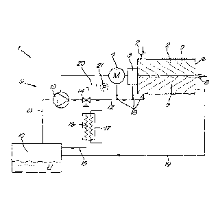
In this case the oil-free compressor 1 shown in figure 1 is
a screw compressor device with a screw compressor element 2,
a transmission 3 (or 'gearbox') and a motor 4 with variable
speed, whereby the oil-free compressor 1 is provided with an
oil circuit 5 according to the invention.
According to the invention, it is not necessary for the oil-
free compressor 1 to be a screw compressor 1, as the
compressor element 2 could also be of a different type, e.g.
a tooth compressor element, scroll compressor element, vane
compressor element, etc.
The compressor element 2 is provided with a housing 6 with
an inlet 7 to draw in a gas and an outlet 8 for compressed
gas. Two mating helical rotors 9 are mounted on bearings in
the housing 6.
The oil circuit 5 will supply the oil-free compressor 1 with
oil 11 to lubricate and if need be cool the components of
the oil-free compressor 1.
These components are for example the gears in the
transmission 3, the bearings on which the helical rotors 9
are mounted in the compressor element 2, etc.
The oil circuit 5 comprises an oil reservoir 10 with oil 11
and an oil pipe 12 to bring the oil 11 to the components of
the oil-free compressor 1 to be lubricated and/or cooled.
A rotary oil pump 13 is provided in the oil pipe 12 to be
able to pump oil 11 from the oil reservoir 10.
CA 03060655 2019-10-21
WO 2018/193325
PCT/IB2018/052065
14
The rotary oil pump 13 is driven by the motor 4 of the
compressor element 2.
The rotary oil pump 13 can be connected directly to the shaft
of the motor 4 or to a drive shaft. This drive shaft is then
connected to the motor 4 via a coupling. Then the gear is
mounted on the driveshaft that is driven by the gearbox. One
or more compressor elements 2 can be driven via the gearbox.
A bypass valve 14 and a bypass pipe 15, that leads from the
oil pipe 12 back to the oil reservoir 10, are provided in
the oil pipe 12 downstream from the rotary oil pump 13.
Although in the example shown the bypass valve 14 is affixed
in the oil pipe 12, it is not excluded that the bypass valve
14 is affixed in the bypass pipe 15. It is not excluded
either that a three-way valve is used that is affixed at the
location of the connection of the oil pipe 12 to the bypass
pipe 15.
The bypass valve 14 will distribute the oil 11 that is pumped
by the rotary oil pump 13: a part will be driven to the
components of the oil-free compressor 1 to be lubricated
and/or cooled via the oil pipe 12, the other part will be
driven back to the oil reservoir 10 via the bypass pipe 15.
In this case, but not necessarily, the bypass valve 14 is a
mechanical valve 14.
CA 03060655 2019-10-21
WO 2018/193325
PCT/IB2018/052065
In a preferred embodiment, the valve 14 is a spring-loaded
valve, i.e. the valve 14 comprises a spring or spring
element, whereby the spring will open the valve 14 more or
less depending on a pressure p upstream or downstream the
5 valve 14.
In this case the valve will be a spring-loaded valve 14 that
will close and open the bypass pipe 15 depending on the
pressure p downstream of the valve 14. When a certain
10 threshold value of the pressure p is exceeded, the valve 14
will open the bypass pipe 14 so that a portion of the pumped
oil 11 will flow via the bypass pipe 15 to the oil reservoir
10.
15 According to the invention an oil cooler 16 is placed in the
bypass pipe 15. This means that the oil 11 that flows via
the bypass pipe 15 can be cooled, but that the oil 11 that
flows via the oil pipe 12 to the components to be lubricated
and/or cooled will not be cooled.
In other words: cooled cold oil 11 will be guided to the oil
reservoir 10 via the bypass pipe 15.
In this case the aforementioned oil cooler 16 forms part of
a heat exchanger 17. The oil cooler 16 could be a plate
cooler for example, but any type of cooler that is suitable
for cooling the oil 11 can be used in this invention.
In this case the oil cooler 16 has a fixed or constant
cooling capacity for a given oil flow and flow of a coolant.
This means that the cooling capacity cannot be adjusted. By
CA 03060655 2019-10-21
W02018/193325
PCT/IB2018/052065
16
adjusting the flow of the coolant, it would indeed be
possible to adjust the cooling capacity. However, this is
not necessary.
From the bypass valve 14, the oil pipe 12 runs to the
components of the oil-free compressor 1 to be lubricated and
cooled if need be. Here the oil pipe 12 will be divided into
subpipes 18 that may be partly integrated in the compressor
element 2.
Furthermore, the oil circuit 5 is provided with a return
pipe 19 to carry the oil 11 from the compressor element 2
back to the oil reservoir 10, after it has lubricated and if
need be cooled the components.
This oil 11 will have a higher temperature.
In the oil reservoir 10 this hot oil 11 will be mixed with
the cooled cold oil 11 that is guided to the oil reservoir
10 via the bypass pipe 15.
The operation of the oil-free compressor 1 with the oil
circuit 5 is very simple and as follows.
When the compressor element 2 is driven by the motor 4, the
mating rotating helical rotors 9 will draw in and compress
air.
During the operation, the different components of the
compressor element 2, the transmission 3 and the motor 4
will be lubricated and cooled.
CA 03060655 2019-10-21
WO 2018/193325
PCT/IB2018/052065
17
As the rotary oil pump 13 is driven by the motor 4 of the
compressor element 2, as of the start-up of the oil-free
compressor 1 it will pump oil 11 and drive it to the
components of the oil-free compressor 1 to be lubricated and
cooled via the oil pipe 12 and subpipes 18.
The change of the flow rate Q of the rotary oil pump 13 as
a function of the speed n of the motor 4 is shown in figure
2.
As can be seen from this drawing, at low speeds n the rotary
oil pump 13 will pump less oil 11 compared to at high speeds
n. This is advantageous, as at low speeds n less lubrication
and cooling will be required and more at high speeds n.
At low speeds n, all oil 11 that is pumped will be driven to
the compressor element 2 and the motor 4, i.e. the bypass
valve 14 will close the bypass pipe 15 so that no oil 11 can
flow back to the oil reservoir 10 along the bypass pipe 15
and the oil cooler 16. As at low speeds n no cooling is
required as the oil 11 will barely warm up, this is not a
problem and this will ensure that the oil 11 does not get
too cold.
The change of the pressure p in the oil pipe 12 downstream
from the bypass valve 14 is shown in figure 3.
The pressure will systematically rise in proportion to the
speed n, until a specific pressure p' is reached
corresponding to the speed n'.
CA 03060655 2019-10-21
WO 2018/193325
PCT/IB2018/052065
18
As of this speed n' a pressure p' is reached such that the
bypass valve 14 will partially be opened to the bypass pipe
15.
As a result, at higher speeds than n', a portion of the
pumped oil 11 will be driven through the bypass valve 14 via
the bypass pipe 15.
This is schematically shown in figure 2 whereby the curve is
divided into two branches: a portion of the oil flow Q
corresponding to zone I will be driven via the oil pipe 12
to the components of the oil-free compressor 1 to be
lubricated and cooled, while the other portion of the oil
flow Q corresponding to zone II will be driven back to the
oil reservoir 10 via the bypass pipe 15.
Because the bypass valve 14 will open, as of the speed n'
the pressure p will no longer rise in proportion to the speed
n of the motor 4, but the curve flattens out, as shown in
figure 3.
The higher the speed n, the more the bypass valve 15 will be
pushed open by the higher pressure p downstream from the
bypass valve 15 in the oil pipe 12. Indeed, at a higher
speed n, the flow rate Q of the rotary oil pump 13 will be
greater, so that this pressure p will also rise such that
the bypass valve 14 will open more.
The spring characteristics of the spring-loaded bypass valve
14 are chosen such that the bypass valve 14 is controlled by
CA 03060655 2019-10-21
W02018/193325
PCT/IB2018/052065
19
the spring such that a preset pressure p is reached in the
oil pipe 12 between the bypass valve 14 and the compressor
element 2 and/or the motor 4 according to the curve of figure
3.
The oil 11 that is guided via the bypass pipe 15 will pass
through and be cooled by the oil cooler 16.
Because the cooled oil 11 that is guided via the bypass
pipe 15 comes to the oil reservoir 10, the temperature of
the oil 11 in the oil reservoir 10 will fall. This cold(er)
oil 11 is then pumped by the rotary oil pump 13 and brought
to the compressor element 2 and/or motor 4.
As at high speeds n more heat is generated in the oil-free
compressor 1, more cooling will be required which is taken
care of precisely by the above method.
At increasing speeds n, the rotary oil pump 13 will always
pump more oil 11 from the oil reservoir 10. As the pressure p
downstream of the bypass valve 14 will always be higher as
a result, this bypass valve 14 will respond to this by always
guiding more oil 11 via the bypass pipe 15, so that the
pressure p does not rise too high and continues to follow
the curve of figure 3.
As a result, with increasing speeds n, ever more oil 11 will
be cooled, so that the rising temperature of the oil-free
compressor 1 can be accommodated at these increasing
speeds n.
CA 03060655 2019-10-21
W32~93325
PCT/IB2018/052065
This is shown in figure 2, whereby the zone II always becomes
greater at higher speeds n.
The above clearly shows that at low speeds n little or no
5 oil 11 is cooled, while at increasing speeds n ever more
oil 11 is cooled.
As a result of this, the oil temperature will be more
constant and higher on average, which ensures that the
10 viscosity of the oil 11 will be lower on average so that
there are fewer oil losses in the rotary oil pump 13 and at
the lubrication locations.
As can be further seen from figure 2, at all speeds n the
15 oil flow Q that goes via the bypass pipe 15 and the oil
cooler 16 (zone II) will be smaller than the oil flow Q that
is driven to the compressor element 2 and/or the motor 4
(zone I).
20 This means that the oil cooler 16 can have smaller dimensions
compared to the known cooling circuits.
The oil 11 of the compressor element 2 and/or the motor 4
will be driven back to the oil reservoir 10 via the return
pipe 19.
This oil 11 will have a higher temperature than the oil 11
in the oil reservoir 10.
In addition to this hot oil 11, the cooled oil 11 will also
come to the oil reservoir 10 via the bypass pipe 15.
CA 03060655 2019-10-21
W02018/193325
PCT/IB2018/052065
21
The two will be mixed together in the ell reservoir 10, which
will result in an oil 11 at a certain temperature between
the temperature of the cooled oil 11 and the hot oil 11.
As of the oil reservoir 10, the rotary oil pump 13 will again
pump the oil 11 and the method and control set out above
will be followed.
Although in the example shown, a spring-loaded mechanical
valve is used as a bypass valve 14, it is possible to use an
electronic bypass valve 14 that is controlled by a
controller 20.
In figure 1, this controller 20 is shown by a dotted line by
way of an example. This controller 20 will control the bypass
valve 14, for example on the basis of a signal from a pressure
sensor 21 that is placed downstream from the bypass valve 14
in the oil pipe 12. The controller 20 will control the bypass
valve 14 so that the pressure p, as registered by the
pressure sensor 21, will follow the path of the curve of
figure 3. In other words: the bypass valve 14 is controlled
such that a preset pressure p is reached in the oil pipe 12
between the bypass valve 14 and the compressor element 2
and/or the motor 4.
Although in the examples shown and described, the oil
circuit 5 is shown separate from the compressor element 2
and the motor 4, it is of course not excluded that the oil
circuit 5 is integrated in or physically forms part of the
compressor element 2 and/or the motor 4.
CA 03060655 2019-10-21
WO 2018/193325
PCT/IB2018/052065
22
In all embodiments shown and described above it is possible
that the oil circuit 5 also comprises an oil filter. This
oil filter can for example, but not necessarily, be affixed
in the oil pipe 12 downstream from the bypass valve 14. The
oil filter will collect any contaminants from the oil 11
before sending it to the compressor element 2 and/or the
motor 4.
The motor 4 will directly drive the compressor element 2 as
well as the rotary oil pump 13. In figure 4, it is shown
that a rotation shaft 22 of the motor 4 is directly driving
the rotary oil pump 13.
The oil circuit 5 will allow that the rotary oil pump 13
pumps up oil 11 from the oil reservoir 10 through an inlet
channel 23 before the rotary oil pump 13, after which the
oil 11 may be guided through the pipe 12 and the subpipes 18
to the nozzles that are positioned on specific locations in
the motor 4 and/or the compressor element 2 for the
lubrication and/or cooling of one or more bearings and other
components of the oil-free compressor 1.
As the rotary oil pump 13 is driven by the motor 4 of the
compressor element 2, it will be at a considerably higher
position level than the oil reservoir 10. This means that
the inlet channel 23, which is running from the oil
reservoir 10 to the rotary oil pump 13, is relatively long.
The rotary oil pump 13 comprises a housing 24 wherein a
stator 25 and a rotor 26 are mounted. The rotor 26 is mounted
CA 03060655 2019-10-21
WO 2018/193325
PCT/IB2018/052065
23
on a rotation shaft 27, which is driven by the rotation shaft
22 of the motor 4.
The rotary oil pump 13 is a gerotor pump, however this is
not a prerequisite of the invention.
The housing 24 is provided with an inlet port 28 for oil 11,
to which the inlet channel 23 is connected, and with an
outlet port 29 for the pumped oil 11.
In figure 5, the inlet port 28 and the outlet port 29 are
clearly visible.
As shown in figure 6, the inlet channel 23 is provided with
a dam 30 near the rotary oil pump 13.
By 'dam 30' is meant a structure which ensures that, when
the motor 4 has stopped, a certain volume of oil 11 will
remain in a space 31 in the inlet channel 23 which is dammed
by the dam 30.
By 'near the rotary oil pump 13' is meant that the
aforementioned remaining volume of oil 11 will remain at a
location such that the rotary oil pump 13 is able to pump up
the oil 11 immediately at the start-up of the rotary oil
pump 13.
This means that the aforementioned remaining volume of oil 11
will for example at least partly be present in the rotary
oil pump 13 or that the remaining volume of oil 11 will be
CA 03060655 2019-10-21
W02018/193325
PCT/IB2018/052065
24
located in the inlet channel 23 right next to inlet port 28
of the rotary oil pump 13.
In figure 6, it is clearly visible that the dam 30 has a
minimal height equal to the height A of the centreline 32 of
the rotation shaft 27 of the rotary oil pump 13 reduced with
half a smallest diameter B of the rotor 26 of the rotary oil
pump 13.
By making the dam 30 at least as high as this minimal height,
indicated by the line C, enough oil 11 will remain in the by
the dam 30 dammed space 31 in the inlet channel 23 between
the dam 30 and the rotary oil pump 13, whereby the rotary
oil pump 13 is completely wetted internally at start-up of
the oil-free compressor 1. Due to this immediate internal
wetting of the rotary oil pump 13 with oil 11, the rotor 26
and the stator 25 will be immediately sealed by this oil 11
such that the suction power of the rotary oil pump 13 is
immediately maximal.
In this case, and preferably, a height D of the dam 30 is
smaller than a maximal height equal to the height A of the
centreline 32 of the rotation shaft 27 of the rotary oil
pump 13 reduced with half a diameter E of the rotation shaft
27 of the rotary oil pump 13.
If the dam 30 would be higher than this maximal height,
indicated by the line F, the level of the remaining oil 11
would be higher than a lowest point of the rotation shaft 27
of the rotary oil pump 13. Because of this, oil 11 would
possibly leak via the rotation shaft 27 of the rotary oil
CA 03060655 2019-10-21
WO 2018/193325
PCT/IB2018/052065
pump 13 and/or sealings would need to be provided on the
rotation shaft 27 of the rotary oil pump 13 to avoid this.
Next to the minimum height C and maximum height F of the dam
5 30, the configuration of the dam 30 is such that in this
case, and preferably, the volume of the oil 11 which might
be present between the rotary oil pump 13 and the dam 30 in
the rotary oil pump 13 and the inlet channel 23, is at least
twice a swept volume of the rotary oil pump 13.
This has the advantage that immediately enough oil 11 is
available in the rotary oil pump 13 and the inlet channel 23
at start-up of the rotary oil pump 13, such that it is not
only possible to immediately wet the rotary pump 13
internally, but also to immediately pump up or pump through
a volume of oil 11 via the outlet port 29 to the oil circuit 5
and so further to the components of the oil-free compressor 1
to be lubricated and/or cooled.
Despite the dam 30 in figures 5 and 6 being designed as a
slanting slope towards the rotor 26 and the stator 25 of the
rotary oil pump 13, it is not excluded that the dam 30 has
another configuration.
In ficure 7 an alternative configuration is shown, whereby
the dam 30 has a stepped form, whereby the inlet channel 23
is as it were provided with a step 33.
Although this embodiment has the advantage that more oil 11
will remain in the space 31 between the dam 30 and the rotary
oil pump 13, it does have the disadvantage that at the
CA 03060655 2019-10-21
WO 2018/193325
PCT/IB2018/052065
26
suction of the oil 11, the oil 11 so to speak flows down via
the step 33, which may result in undesired turbulences. In
the embodiments of figures 5 and 6, the oil 11 will so to
speak flow down from the dam 30.
The operation of the oil-free compressor 1 is very
straightforward and as follows.
For the start-up of the oil-free compressor 1, preferably
the following steps are taken:
- bringing oil 11 into the oil circuit 5 at a position
downstream and higher than the rotary oil pump 13 until
the space 31 is completely filled with oil 11; and
- then starting the motor 4.
The oil 11 that is brought into the oil circuit 5 may flow
down to the rotary oil pump 13 and fill both the rotary oil
pump 13 and the inlet channel 23 in the space 31 between the
dam 30 and the rotary oil pump 13 to a level equal to the
height D of the dam 30.
When the motor 4 is then started, the compressor element 2
and the rotary oil pump 13 will be driven and the oil 11
that is brought into the oil circuit 5 and is now located in
the rotary oil pump 13 and the aforementioned space 31, will
ensure that the rotary oil pump 13 is able to immediately
pump and transfer oil 11 to the oil circuit 5, such that the
compressor element 2 is immediately provided with the
necessary oil 11 right from the start-up of the oil-free
compressor 1.
CA 03060655 2019-10-21
W02018/193325
PCT/IB2018/052065
27
Alternatively, it is also possible that firstly a lubricant
which is less volatile than the oil 11 is brought into the
rotary oil pump 13 internally, before the motor 4 is started.
Such method is preferably applied at the assembly of the
oil-free compressor 1, such that at a first start-up of the
oil-free compressor 1, the less volatile lubricant is present
In the rotary oil pump 13.
It is of course not excluded that both methods are combined,
whereby at the first start-up a less volatile lubricant is
brought in and whereby at a subsequent start-up of the oil-
free compressor 1 oil 11 is brought into the oil circuit 5.
From the moment that the motor 4 is started, the rotary oil
pump 13 will immediately pump up oil 11 from the oil
reservoir 10 via the inlet channel 23.
The pumped oil 11 will then leave the rotary oil pump 13 via
the outlet port 29 and come into the oil circuit 5 from where
it is transferred to different nozzles at different to be
lubricated and/or cooled components of the compressor
element 2 and/or the motor 4.
The compressor element 2 and/or the motor 4 will therefore
be almost immediately provided with oil 11 from the start-
up of the motor 4 and the oil-free compressor 1.
It is not excluded that the oil-free compressor 1 comprises
a sensor configured to register whether oil 11 is present in
the space 31 between the rotary oil pump 13 and the dam 30.
CA 03060655 2019-10-21
W02018/193325
PCT/IB2018/052065
28
The aforementioned sensor may be any type of oil-level
sensor, but also an oil pressure sensor or oil temperature
sensor according to the invention.
For the start-up of an oil-free compressor 1 with such
sensor, the motor 4 is preferably only started after oil 11
has been detected in the inlet channel 23 between the rotary
pump 13 and the dam 30.
If no oil 11 is detected, the oil-free compressor 1 is not
started, but instead a warning signal is sent out to the
user.
It is clear that the sensor and the aforementioned method to
control the lubrication and/or cooling of the oil-free
compressor 1 at start-up, may be combined with the previously
described methods. This method will incorporate an
additional safety feature to prevent that the oil-free
compressor 1 may be started without oil 11 being present in
the inlet channel 23 between the rotary oil pump 13 and the
dam 30.
It is also possible that the oil-free compressor 1 comprises
a fluid connection between the oil reservoir 10 and the space
31 between the rotary oil pump 13 and the dam 30, whereby
the fluid connection is configured to transfer oil 11 from
the oil reservoir 10 to the space 31 between the rotary oil
pump 13 and the dam 30.
CA 03060655 2019-10-21
WO 2018/193325
PCT/IB2018/052065
29
This may for example be realized by means of a small pump
which is manually or electrically operated.
When the oil-free compressor 1 is provided with such a fluid
connection, the following method may be executed for the
start-up of the oil-free compressor 1:
- transferring oil 11 from the oil reservoir 10 to the
space 31 between the rotary oil pump 13 and the dam 30,
until the space 31 is completely filled with oil 11;
and
- then starting the motor 4.
It is of course not excluded that the oil-free compressor 1
is also provided with a sensor configured to register whether
oil 11 is present in the inlet channel 23 between the dam 30
and the rotary oil pump 13.
In this case, when no oil 11 is detected at start-up, a
signal will be sent out to the user to transfer oil 11 from
the oil reservoir 10 to the space 31 between the rotary oil
pump 13 and the dam 30 by operating the small pump or, when
this small pump operates electrically, the small pump will
be automatically started by the oil-free compressor 1 in
order to ensure that oil 11 is transferred from the oil
reservoir 10 to the space 31 between the rotary oil pump 13
and the dam 30, after which it is possible to start the
motor 4 smoothly without problems.
The present invention is by no means limited to the
embodiments described as an example and shown in the
drawings, but an oil circuit according to the invention and
CA 03060655 2019-10-21
WO 2018/193325
PCT/IB2018/052065
an oil-free compressor provided with such an oil circuit can
be realised in all kinds of forms and dimensions without
departing from the scope of the invention.