Note : Les descriptions sont présentées dans la langue officielle dans laquelle elles ont été soumises.
CA 03063295 2019-11-12
WO 2018/220153
PCT/EP2018/064411
Calorimeter
The invention relates to a calorimeter. Such a calorimeter can be used for the
analysis of
chemical or physiological processes which absorb or generate heat. Heat can be
an indicator
for a chemical reaction, a metabolic activity or a cellular function, e.g. a
cellular function in
micro-organisms. In the most general sense, a calorimeter is a device
measuring the heat
produced by a sample inside a container being used as a recipient of such a
sample. An
isothermal calorimeter is a calorimeter which continuously removes and
simultaneously
measures the heat produced in such a sample while keeping the temperature
difference
between the interior of the container and the external heat sink minimal,
ideally close to
zero. The heat produced corresponds to a heat flow which can be measured by a
sensor,
such as a contact temperature sensor, e.g. a thermometer, a thermo-electrical
sensor, a
thermistor, a transistor, a resistance temperature detector (RTD), a platinum
resistance
thermometer, a thermo-mechanical sensor, or a non-contact sensor, such as an
infrared
optical sensor, a diode.
Biological processes can produce heat in the range of less than 1 microwatt
per milliliter
sample volume, which requires a high thermal sensitivity of the sensor used,
thus involving
microcalorimetry, in particular isothermal microcalorimetry allowing the
detection of heat
energies in the Nanowatt range. The heat flux to be detected can be in the
range of 1
nanowatt up to and including 1 milliwatt. Preferably the heat flux can be in
the range of 0.1
microwatt up to and including 1080 microwatt.
A thermistor is a type of sensor which can be used in microcalorimetry. A
thermistor is a
thermally sensitive resistor. In particular a negative temperature coefficient
thermistor (NTC)
can be used, which is characterized in that the resistance of the thermistor
is inversely
proportional to the temperature sensed by the thermistor. Thermistors are
characterized by
a high gain, which enables them to resolve very small temperatures in a given
temperature
range. However, the thermistors require extensive cleaning and sterilization
between
measurements, therefore such thermistors may not be suitable if a measurement
on a
multitude of samples has to be performed within a limited time period.
A thermoelectric element is a device that converts a current into a heat flow
or a heat flow
into a current making use of thermoelectricity. A thermocouple, which is a
bimetallic sensor,
makes use of this principle by producing an electrical potential difference
proportional to the
temperature difference between the two surfaces. Thermoelectricity describes
the correlation
1
CA 03063295 2019-11-12
WO 2018/220153
PCT/EP2018/064411
between temperature and electricity. A thermoelectric element can be used for
converting an
electrical current into a heat flow, or a heat flow into a current. The
conversion of a current
into a heat flow is known as the Peltier effect, finding its application in a
Peltier element. A
Peltier element consists of two electrically conducting materials which are
different from each
other and which are connected with each other at one of each ends. The Peltier
effect can
be observed best if the electrically conducting materials are semiconductors.
One of the
electrically conducting materials is a p-type semiconductor, whereas the other
electrically
conducting material is a n-type semiconductor. An electric circuit including a
battery is
connected to the free ends of the p-type semiconductor and the n-type
semiconductor. If the
electric circuit is closed, electrons from the negative pole of the battery
flow into the
direction of the p-type semiconductor and move along inside this p-
semiconductor by filling
up the positive "holes" in this material until they arrive at the boundary
between the p-type
semiconductor and the n-type semiconductor. Due to the fact that in the n-type
semiconductor, all available "holes" in the crystal structure have a negative
polarity, the
movement of the electrons is at least temporarily blocked by the boundary and
requires
energy to overcome this blockage. If the boundary is attached to a bridging
heat exchange
surface, such a bridging heat exchange surface cools as an energy input is
required to
deblock the electrons and "push" them through the n-type semiconductor to
uphold the
potential difference as applied by the electric circuit with the battery. On
their way to the
positive pole of the battery, the energy transported together with the
electrons dissipates at
the respective ends of the p-type semiconductor and the n-type semiconductor,
whereby a
heat flux is generated. If a heat exchange surface is provided at the source-
sided ends of the
p-type semiconductor and the n-type semiconductor, the temperature of this
heat exchange
surface rises, such that it becomes a hot surface.
If two different materials are connected at their ends together they can form
a loop whereby
the contact surfaces of the two materials are brought to different
temperatures the
thermoelectricity results in the generation of an electric circuit current. In
case that the same
arrangement of a p-type semiconductor and a n-type semiconductor is used, the
heat
supplied to the boundary connecting surface of the two semiconductors results
in a
thermodiffusion as the hot end of the p and n semiconductors contain more
electrons of a
higher energy which move towards the cold end and the cold end containing more
electrons
of a low energy moving to the hot end. This thermodiffusion results in a
current difference
also due to the use of different materials. In case the electrical circuit is
interrupted, a
potential difference results, which can be measured as a voltage, the Seebeck
voltage. The
2
CA 03063295 2019-11-12
WO 2018/220153
PCT/EP2018/064411
Seebeck voltage is ideally roughly parallel to the temperature difference. A
thermoelement
can be used as a temperature sensor, provided it is calibrated accordingly.
A Peltier element can be used for the conversion of current into a heat flow.
The inverse
operation of a Peltier element results in a current generator, whereby by
means of the
Seebeck effect the heat flow can be converted into a current. If the electric
circuit is
interrupted this current results in a potential difference, which can be
measured as a voltage.
A thermoelement can be considered as a device generating an electromotive
force and may
be used as a sensor by measuring a voltage obtained from a current from a heat
flow
resulting from thermodiffusion.
A plurality of thermocouples can be combined to form a stack, a so-called
thermopile. Such a
thermopile is a multi-layer thermocouple, which can be used to measure a heat
flow from a
sample involving e.g. a biological process to a heat sink using a
thermoelectric element as
sensor.
McKinnon et al. show in the article "Commercial Bismuth Telluride-based
Peltier Plates for
Use as Heat Flux Transducers (A Concept) by Clinton McKinnon, Ronald R.
Bernardini,
Wayne Thesher, Stuart L. Ruis, David W. Yarbrough that low-cost, commercially
available
bismuth telluride peltier plates can be used to measure the thermal
performance of building
elements and / or thermal insulation. The peltier plates are arranged around a
sample
containing a central transducer which is also a bismuth telluride module. The
voltage
obtained was about 270 mV without amplification and about 1300 mV with
amplification.
This means that such an apparatus appears to be unsuitable for any measurement
in the
range of picovolts (10-12 Volts) resulting from heat flows attributed to e.g.
bacterial activity in
a sample.
The use of multi-channel calorimeters has been described in US 2004/0107986.
Such a
multi-channel calorimeter comprises a plurality of wells arranged in an array,
whereby each
of the wells is configured as a sample container. The sample container
comprises a bottom
surface, which is configured to receive a thermal sensor, such as a
thermistor. The
thermistor is received in a corresponding recess of the bottom surface. The
bottom surface is
configured to provide minimal resistance to heat flow, therefore the wall
thickness of the
bottom surface is reduced with respect of the other wall surfaces of the well
which are not in
contact with any thermal sensor. A plurality of wells can be arranged in a
regular pattern on
the well plate to allow for parallel measurements.
3
CA 03063295 2019-11-12
WO 2018/220153
PCT/EP2018/064411
A drawback of the known calorimeter is to be seen in the fact that it is
expensive to
manufacture and of a highly complex configuration. The heat of growing
microorganisms,
e.g. bacteria, were measured by sensors on the known calorimeter setting
todays gold
standard for the temporal detection of heat production. There is a need of
optimizing the
properties of the sensors and arranging the sensors in a more efficient way. A
probe for
microcalorimeter of a simplified configuration is disclosed in GB 2093995 A.
The probe
comprises a hollow cylindrical body for receiving the sample container, for
instance an
ampoule. The probe can be connected to heat transducers, which are configured
as Peltier
elements. However, an adapter part is required to provide a transition from
the cylindrical
jacket of the probe to the flat Peltier element. The probe, the adapter and
the optional
additional tube arranged on the jacket of the probe all contribute to heat
dissipation. For this
reason, the microcalorimeter GB 2093995 A is not considered suitable for
measuring
microorganism activity or other samples with a comparable heat generation.
It is thus an object of the invention to provide a device and a method for
reducing the time
required for completion of an analysis. In particular, it is an object of the
invention to
provide a device and method for obtaining a rapid result of microorganism
activity in a
substrate. It is a further object to capture the major portion of heat
developed in the sample
by the heat transducer element.
It is a further object of the invention to provide a calorimeter which needs
much less
complex electronics and is simple in its manufacture and easy to assemble.
It is a further object of the invention to provide a method for measuring the
heat generated
or absorbed by an energy source e.g. pathogens, cells or bacterial activity,
by a calorimeter
according to one of the preceding embodiments, whereby the measurement can be
completed in a time frame of at most 8 hours, preferably at most 4 hours, most
preferably at
most 2 hours. According to an embodiment, the measurement can take at least 10
minutes.
According to an exemplary embodiment, the measurement can last for at least 30
minutes.
According to an embodiment the measurement period can extend from at last 10
minutes to
at most 8 hours. According to an exemplary embodiment, the measurement period
can
extend from at least 30 minutes to at most 4 hours. According to a preferred
exemplary
embodiment, the measurement period can extend from at least 30 minutes to at
most 2
hours.
4
CA 03063295 2019-11-12
WO 2018/220153
PCT/EP2018/064411
It can be a further object of the invention to perform a measurement of the
heat flux
generated by cultivation of microorganisms and in particular the metabolism of
micro-
organisms.
The problem is solved by a device according to claim 1. Further advantageous
embodiments
of the device are subject to the dependent claims.
If the term for instance is used in the following description, the term
relates to
embodiments or examples, which is not to construed as a more preferred
application of the
teaching of the invention. The terms "preferably" or "preferred" are to be
understood such
that they relate to an example from a number of embodiments and/or examples
which is not
to construed as a more preferred application of the teaching of the invention.
Accordingly
the terms "for example", "preferably" or "preferred" may relate to a plurality
of embodiments
and/or examples.
The subsequent detailed description contains different embodiments of the
calorimeter
according to the invention. The calorimeter can be manufactured in different
sizes making
use of different materials, such that the reference to a specific size or a
specific material is to
be considered as merely exemplary. In the description, the terms contain ,
comprise ,
are configured as in relation to any technical feature are thus to be
understood that they
contain the respective feature, but are not limited to embodiments containing
only this
respective feature.
Even if the calorimeter has been particularly applied for the cultivation of
microorganisms
and in particular the metabolism of micro-organisms, it is in no way
restricted to any
particular energy source. The sample to be measured can contain any energy
source
producing or absorbing heat.
A calorimeter for measuring a heat flux of a sample comprises a container, a
first heat sink
and a second heat sink. The sample is arranged in the container, whereby the
first heat sink
and the second heat sink are arranged at a distance from each other on at
least one of the
outer surfaces of the container. Each of the first and second heat sinks
comprise a heat
transducer element. The first heat sink comprises a first heat transducer
element and the
second heat sink comprises a second heat transducer element. Each of the first
and second
heat transducer elements comprise a heat receiving surface and a heat
absorbing surface
configured to generate an electromotive force equivalent to the heat flux to
or from the
5
CA 03063295 2019-11-12
WO 2018/220153
PCT/EP2018/064411
respective heat sink to be sent to a detecting unit for obtaining an
electrical potential
representing the heat flux leaving or traversing the container. The heat flux
can have a
positive or negative value, depending on the nature of the energy source,
which can be a
heat source or a source of cold. The first and second heat transducer element
are in direct
contact with the container which contains the sample.
According to an embodiment, the container is supported by the first and second
heat
transducer elements. Advantageously, there is no other heat flux in or out of
the container
than through the first and second heat transducer elements.
The placement of the sample container between the first and second heat
transducer
elements allows in particular a measurement of the heat generated in the
sample container
in a stationary manner. There is thus no requirement of any flow through the
sample
container. Any temperature change can be directly attributed to the heat
generated in the
sample which is to be detected by the first and second heat transducer
elements.
According to an embodiment, the first heat transducer element is mounted in a
flipped
configuration with respect to the second heat transducer element. One of the
heat absorbing
surfaces and one of the heat receiving surfaces can face the container surface
and/or can be
attached to the container surface. One of the heat absorbing surfaces and one
of the heat
receiving surfaces can face the heat sink. One of the heat absorbing surfaces
and one of the
heat receiving surfaces can be attached to the heat sink. If the heat
absorbing and/or heat
receiving surfaces are attached to the container surface, e.g. the container
wall, heat is
transferred to the heat receiving surfaces and/or heat absorbing surfaces
predominantly
through conduction. The heat transfer by conduction is particularly
advantageous if a portion
of the container covered by at least one of the heat absorbing or heat
receiving surfaces
corresponds to at least 50 % of the container surface. More preferably the
portion of the
container covered by at least one of the heat absorbing or heat receiving
surfaces
corresponds to at least 65 % of the container surface. Most preferred, the
portion of the
container covered by at least one of the heat absorbing or heat receiving
surfaces
corresponds to at least 80 % of the container surface.
The container can be moved into the measuring position between the first and
second heat
transducer element freely, e.g. depending from a ceiling to which it is
attached to. The
container is configured such that it is adaptable to fit precisely into the
gap formed by the
first and second heat transducer element. In particular, the gap can be
configured such that
it is just a bit smaller than the space required by the container. Thereby an
optimal contact
6
CA 03063295 2019-11-12
WO 2018/220153
PCT/EP2018/064411
between the the container and the first and second heat transducer element can
be
achieved.
The first and second heat transducer elements can include an insulating member
which can
be arranged between the heat sink and the container. The insulating member can
be a
thermally conductive element, which shows good electrical insulation
properties. Each of the
heat receiving surfaces and the heat absorbing surfaces can be contained in
such an
insulating member or can be configured as an insulating member. A heat
receiving surface
and a heat absorbing surface may be disposed with a wall thickness greater
than zero. The
heat absorbing surface can be a part of a heat absorbing plate. The heat
absorbing surface
can comprise a heat absorbing material. The heat receiving surface can be
configured as a
heat receiving plate. The heat receiving surface can comprise a heat receiving
material. The
heat absorbing surface can be a part of a heat absorbing plate. The heat
absorbing surface
can comprise a heat absorbing material. The heat receiving surface can be
configured as a
heat receiving plate. The heat receiving surface can comprise a heat receiving
material.
A heat receiving material comprising the heat receiving surface and/or a heat
absorbing
material comprising the heat absorbing surface may have a wall thickness of up
to 7 mm,
preferably up to 5 mm more preferred up to 2 mm. The insulating member can be
arranged
directly next to the container surface, thus the container and the insulating
member have a
surface in common. The insulating member can touch the container surface. Each
of the
heat receiving surfaces and the heat absorbing surfaces can touch the
container surface. The
shape of any of the heat receiving and heat absorbing surfaces can correspond
to the shape
of the container surface.
The insulating member facing the heat sink can be arranged directly next to
the heat sink,
thus the heat sink and the insulating member have a surface in common. The
insulating
member can touch the heat sink surface. Each of the heat receiving surfaces
and the heat
absorbing surfaces can touch the heat sink surface. The shape of any of the
heat receiving
and heat absorbing surfaces can correspond to the shape of the heat sink
surface.
In particular, the heat absorbing surface of one of the first and second heat
transducer
elements faces the outer container surface and the heat absorbing surface of
the other of
the first and second heat transducer elements faces the heat sink. This
configuration allows
according to an embodiment a heat flow from the first heat transducer through
the container
to the second heat transducer. The heat flow continues through the heat sink
back to the
first heat transducer. This configuration allows according to an embodiment a
heat flow from
7
CA 03063295 2019-11-12
WO 2018/220153
PCT/EP2018/064411
the second heat transducer through the container to the first heat transducer.
The heat flow
continues through the heat sink back to the second heat transducer. The heat
sink can
operate as a damping element if a sample is introduced into the system which
is too cold or
to hot. Advantageously, the heat capacity of the heat sink is considerably
larger than the
heat capacity of the sample. Any of the first or second heat transducers,
which are in
particular configured as Peltier elements, can have a warmer and a colder
surface. Under a
warmer surface, it is intended a surface having a higher temperature than the
environment.
Under a colder surface, it is intended a surface having a lower temperature
than the
environment. The Peltier element is thus disposed with a polarity, which
results in a positive,
negative or neutral measured signal depending on its orientation in the
calorimeter.
According to an embodiment, the electromotive forces generated by the first
and second
heat transducer elements are transformed in the detecting unit into an output
voltage. Each
of the first and second heat transducer elements can comprise a positive and a
negative
connector. Each of the positive and negative connectors can be configured to
be connected
to the heat absorbing and heat receiving surfaces. The electrical potential
difference
between the positive connector and the negative connector of the first heat
transducer
element results in a current to be obtained as the output the of first heat
transducer element
resulting from a heat flux from the container to the first heat sink. The
current flows from
the positive connector through an electric conduit, such as a wire to the
detecting unit. Thus,
.. the heat transfer elements provide a defined electrical configuration and a
directed heat flow
is generated through the heat transfer elements traversing the container
containing the
sample and a corresponding electrical signal is generated.
According to an embodiment, the first and second heat transducer elements are
mounted in
such a way that the currents produced by the non-zero Seebeck effect that
occurs if the
container and the first and second heat sinks are at the same temperature
compensate each
other.
According to an embodiment, the electromotive forces generated by the first
and second
heat transducer element are configured to be transformed into an output
voltage in the
detecting unit. The output voltage is according to this embodiment
proportional to the heat
flux. The detecting unit can comprise a first resistor R1 and a second
resistor R2. The ratio
of resistances of resistors R1/R2 can be used to adjust the output voltage if
the temperature
of the first heat sink and the second heat sink and the container is the same.
If the output
8
CA 03063295 2019-11-12
WO 2018/220153
PCT/EP2018/064411
voltage can be adjusted by the ratio of resistances of resistors R1 and R2, a
more easy
stabilization is obtained as compared to the use of an offset voltage.
According to an embodiment, the detecting unit comprises a first resistor R1,
a second
resistor R2, an amplifier and a feedback resistor Rf, an electric conduit
leading from a
connector of the first heat transducer element to the first resistor R1 and an
electric conduit
leading from a connector of the second heat transducer element to the resistor
R2, and the
first resistor R1, the second resistor R2 and the feedback resistor Rf are
connected to a
negative input of the amplifier. The electric conduits from the connectors of
the first and
second heat transducer elements can be combinable in a collecting conduit at a
summing
point arranged downstream of the resistors R1, R2. According to an embodiment,
the
collecting conduit is received in a summing amplifier, such that an output
voltage can be
generated at the output of the summing amplifier. Thus the net currents
arriving through R1
and R2 from the first and second heat transducer elements at the summing point
are
converted to an output voltage at the output of the amplifier. In particular,
the resistances of
the first and second resistors R1 and R2 are adjustable, whereby the currents
from the
electric connectors of the first and second heat transducer elements are
compensated at the
summing point. If therefore, the heat transducer elements are arranged in a
flipped position
the heat flowing into the container through one of the heat transducer
elements and the
heat leaving the container through the other heat transducer element generates
no output
voltage. In fact, the output voltage generated at the first heat transducer
element has the
same absolute value as the output voltage generated by the second heat
transducer element
if the first and second heat transducer elements are exactly the same. Thus,
the throughput
of heat is not detected. If the first and second heat transducer elements
differ slightly from
each other with respect to their non-zero Seebeck effect, a differential
output voltage will be
detected by the detecting unit. This differential output current can be
compensated by
adjusting the resistance of at least one of the resistors R1, R2.
When performing a measurement with a calorimeter according to any of the
embodiments,
the current from the first heat transducer element and the current from the
second heat
transducer element are thus summed up when using a detecting unit according to
any of the
preceding embodiments. Due to the fact, that one of the resistors R1, R2 is
electrically
connected to the positive connector and the other of the resistors R1, R2 is
connected to a
negative connector, the current flows in opposite senses in the electrical
conduits leading to
the resistors R1, R2. By summing up these currents of opposite sense at the
summing point,
which is arranged between the resistors R1, R2 and the input of the amplifier,
a difference of
9
CA 03063295 2019-11-12
WO 2018/220153
PCT/EP2018/064411
the current from the first heat transducer element and the opposite current
from the second
heat transducer element is obtained. The resulting current from the summing
point is fed
into the input of the amplifier, thereby generating an output voltage that
compensates these
currents through the feed back resistor Rf. The output voltage corresponds to
the heat
generated by the sample in the container. Thereby, the non-zero Seebeck
currents are
canceled out, such that the calorimeter is capable of measuring very low heat
fluxes without
having to compensate electronically the non zero Seebeck effect.
The resistance of the resistors R1 or R2 should according to an embodiment be
very low and
can be zero Ohm. Thereby it is possible to measure the entire current produced
by at least
one of the first and second heat transducer elements. The ratio of the
resistors R1/R2 can be
used to finetune the zero output voltage baseline obtained when the container
and heat sink
are all kept at the sme temperature and no heat is produced anywhere in the
system.
The first and second heat transducer elements emit a standby current. The
standby current
generated by the first heat transducer element most likely differs from the
standby current
of the second heat transducer element if a sample without energy source is
used. A
calibration can be performed by adjustment of the resistances of resistors R1,
R2 to
compensate for any deviations of the standby currents provenient from the
first heat
transducer element with respect to the second heat transducer element due to
manufacturing differences. If the calibration is not performed, a standby
current would be
measured in addition to the current resulting rrom the heat flux, whereby the
measurement
value of the heat flux of the sample to be detected in operation would be
influenced.
In accordance with the principles of isothermal microcalorimetry, the
temperature of the
environment is advantageously kept constant. According to an embodiment, the
preferred
temperature is 37 C.
According to an embodiment any of the first or second heat transducer elements
can
comprise a heat flow detector, which can include a semiconductor. The heat
transducer
element can comprise a layer including a conductive p material, and a layer
including a
conductive n-material arranged next to each other. Each of the layers
including conductive p
materials or layers including conductive n materials may comprise a
semiconductor. By a
heat transfer resulting from a heat flux, an electron flow is induced. The
electron flow is
collected by the electrical connectors arranged at two opposite ends of each
layer including
p-type conductive materials and each layer including n-type conductive
materials. In the
layer containing the p-type conductive materials, the electrons progress in
one direction e.g.
CA 03063295 2019-11-12
WO 2018/220153
PCT/EP2018/064411
from the container to the heat sink. The electrons are conducted by an
intermediate
connector to the next layer containing the n-type conductive materials. The
electrons are
blocked and can only pass on, if they acquire sufficient energy to be able to
be transferred
over or across the layer including n-type conductive materials. The heat sink
can form a
reservoir for this energy, therefore a heat flux from the heat sink to the
connector leads to a
gain in energy for the electrons, which can pass the layer including n-type
conductive
materials to be transported to a subsequent layer including p-type conductive
materials in
case a plurality of such layers are interconnected in a stack.
If the stack covers a large surface portion of the container, substantially
all heat generated
in the container is transferred through the stack to the heat sink.
For the operation of the calorimeter according to any of the embodiments an
energy source
can be provided in the container. The container can contain a sample.
According to an
embodiment, the sample can contain an energy source, such that heat can be
generated by
said energy source to provide the heat flux. The heat flux generated by the
energy source is
detectable by at least one of the first and second heat transducer elements
and the
detecting unit.
In turn, the calorimeter can be used to detect the presence of the energy
source in the
sample, which is detectable by a deviation from the expected heat flux in a
container not
containing an energy source or containing a reference energy source. Due to
the fact, that
any differential heat flow results in an output voltage, the presence of the
energy source is
detectable by comparing the actual output voltage to the expected output
voltage of a
reference sample not containing an energy source or a reference energy source.
The deviation from the expected heat flux results in a deviation of the
detected output
voltage, such that a difference between the detected output voltage and an
expected output
voltage is obtainable. The difference between the detected output voltage and
an expected
output voltage is proportional to the heat flux resulting from the energy
source in the
sample. In addition, the presence of the energy source in the sample can thus
be detected
by the deviation of the detected output voltage from the expected output
voltage of a
reference sample not containing an energy source or containing a reference
energy source.
In particular, the energy source comprises a chemical reaction, which can be
one of an
exothermic chemical reaction or an endothermic chemical reation. The heat flux
is increased
by the energy source, if the energy source generates energy. The heat flux is
decreased by
11
CA 03063295 2019-11-12
WO 2018/220153
PCT/EP2018/064411
the energy source if the chemical reaction is an endothermic chemical
reaction. In particular,
the occurrence of the chemical reaction results in a heat flux which is
detectable in the
sample. By an arrangement of a calorimeter according to any of the embodiments
in the
regime of an isothermal microcalorimetry a heat flux of in the nanowatt or
picowatt range
can be detected.
A method for measuring a heat flux with a calorimeter, comprises the step of
measuring a
deviation from an expected heat flux to a measured heat flux attributable to a
heat source in
the sample. The measurement can be completed in less than 8 hours, preferably
less than 4
hours, most preferred less than 2 hours, which requires that the instrument
gets into a
thermally stable condition as fast as possible. The thermally stable condition
can be reached
faster, if a constant temperature is maintained not only during the
measurement, but also
before the measurement and thereafter. For biological processes, preferably a
temperature
of 37 C can be used. The temperature can be kept constant by the use of at
least one,
preferably multiple insulating layers protecting the calorimeter, in
particular, the container,
.. the sample, the heat sinks, the heat transducer elements. In order to
eliminate temperature
effects from the detecting unit, also the detecting unit can be contained in
the insulation. To
keep the temperature constant, advantageously, the temperature of the
detecting unit can
be controlled.
In particular, a deviation from the expected heat flux results in a deviation
of the detected
electrical potential, such that a potential difference between the detected
electrical potential
from an expected electrical potential is obtained. The expected electrical
potential can
correspond to a zero output voltage, if the calibration as previously
described is performed
prior to the measurement.
The embodiments further relate to the use of a calorimeter according to any of
the
preceding embodiments for detecting the presence of an energy source, such as
a chemical
reaction or biological processes, pathogens, cells, e.g. tumorous cells, or
microorganisms,
such as bacteria, viruses or funghi in a sample. The sample can be liquid,
solid or gaseous.
The sample can be solid, opaque or transparent. For instance, the sample can
be one of
blood, blood cells, blood products, platelets, blood plasma, synovial fluids,
sperm,
cerebrospinal fluid or urine. The sample processed can be recovered and
subjected to
additional analyses as the sample remains almost undisturbed during the
measurement.
An advantage of the calorimeter according to the invention is that the
calorimeter can be
manufactured in a simple manner and at reduced costs as compared to prior art
12
CA 03063295 2019-11-12
WO 2018/220153
PCT/EP2018/064411
calorimeters. A further advantage of the calorimeter is the availability of
the results of the
tests performed therewith within the time span of at most 8 hours, depending
on the
concentration and growth-rate of the micro-organism, which allows for a rapid
pre-screening
of a multitude of samples. Furthermore, the calorimeter can dispense with any
reference
.. sample. A reference sample is not needed as the current difference is
measured. The
calorimeter just requires a single initial calibration to compensate for any
manufacturing
differences between the first and second heat transducer elements.
Considering a detection limit of 200 W of heat production about a 100000
bacteria are
needed to reach the detection limit according to Braissant et al. "Isothermal
Microcalorimetry
for the Investigation of Clinical Samples: Past and Present, chapter 19, pages
356, 357.
Considering a range of 0.01 pW/cell up to 329 pW/cell for the heat production
rate, the
sample size could range from about 1000 to 20 million cells if a detection
limit of 200 nW is
considered.
Apart from the advantage of a rapid screening of a multitude of samples,
sample data can be
.. analyzed with a growth model to allow the rapid determination of the
sample's growth rate.
As already pointed out by Braissant et al., the heat production pattern could
be used to
identify the pathogen. In addition, a comparison between untreated samples and
samples
added with different compounds allows for instance a rapid comparison of the
efficacy of a
molecule against a given pathogen or cancer type to evaluate the activity of a
new
.. compound or a microorganism or a cell in vitro.
A number of embodiments are shown in the subsequent drawings.
Fig. 1 shows an arrangement of a calorimeter according to the prior art,
Fig. 2 an arrangement of a calorimeter according to a first embodiment of the
invention,
Fig. 3 an arrangement of a calorimeter according to a second embodiment of the
invention,
.. Fig. 4 a detail of the first heat sink according to one of the previous
embodiments,
Fig. 5 a detail of the second heat sink according to one of the previous
embodiments,
Fig. 6 a detail of a heat transducer.
Fig. 1 shows an arrangement of a calorimeter of the prior art, such as the
calorimeter
disclosed by McKinnon et al. The calorimeter according to Fig. 1 consists of a
stack of
13
CA 03063295 2019-11-12
WO 2018/220153
PCT/EP2018/064411
components 1, a hot plate 2, a cold plate 4 a first sample 9, a second sample
11 and a heat
flux transducer 10 sandwiched between the first sample 9 and the second sample
11.
The hot plate 2 is fabricated from 40 mm by 40 mm by 4 mm peltier plate. One
face of the
hot plate 2 is attached to a heat sink 16 which can be cooled by a fan 7 on
one face and to a
copper plate 3 on the other face. The copper plate 3 can have the same surface
of 40 mm
by 40 mm and a thickness of 1 mm. The cold plate 4 is fabricated from 40 mm by
40 mm by
4 mm peltier plate. One face of the cold plate 4 is attached to a heat sink 6
which can be
cooled by a fan 8 on one face and to a copper plate 5 on the other face. The
copper plate 5
can have the same surface of 40 mm by 40 mm and a thickness of 1 mm. The
polarity of the
peltier plate forming the hot plate 2 is reversed with respect to the polarity
of the peltier
plate forming the cold plate 4.
The heat flux transducer 10 placed between the hot and cold plates 2, 4 is
configured as a
Peltier plate. Each of the hot and cold plates 2, 4 is equipped with a DC
power supply to
control the Peltier plates for cooling. By variation of the DC supply to the
hot plate 2
temperature differences are obtained. A heat transfer occurs from the lower
hot plate 2
through the copper plate 3, the sample 9, the heat flux transducer 10, the
sample 11, the
copper plate 5 and the cold plate 4. The stack of components is housed in a
cladding made
of expanded polystyrene, shown as lateral walls 12, 13 in Fig. 1.
The heat flux transducer 10 is also referred to as a Seebeck module. The heat-
flux
transducer can be configured as a bismuth-telluride module (BTM). The bismuth-
telluride
module contains an alloy of bismuth and telluride. In analogy to bimetallic
thermocouples, a
BTM exhibits electrical properties when a thermal gradient is applied
transversely through
the material. A single semiconductor pellet produces approximately four times
the output of
a single K type thermocouple junction, which is known as the Seebeck effect. A
BTM with the
overall dimensions of 40 mm by 40 mm by 4 mm thereby generates a potential of
15 Volt
and a current of 4 amp.
The Seebeck module is responsible for creating the so-called Seebeck effect, a
voltage
gradient resulting from the temperature gradient. The voltage gradient
obtained from
measurement of the voltage of the Seebeck module can be digitized and logged
or
conditioned with an operational amplifier before digitizing. The midrange
unamplified signal
mean was 270 +/- 2mV whereas the midrange unamplified signal mean was 1300 +/-
1.4mV. The temperature differences have been increased incrementally and the
Seebeck
outputs have been recorded. In case an expanded EPS sample with a thickness of
25 mm
14
CA 03063295 2019-11-12
WO 2018/220153
PCT/EP2018/064411
with a density of 10.7 kg/m3 is used as sample 9, 11 in the configuration as
shown in Fig. 1,
it is observed that the Seebeck voltage increases roughly linearly with the
temperature
difference according to an equation correlating the voltage y with the
temperature difference
x: y = kx + d with k=4.2436 and d=64,41. The slope coefficient k is small due
to the
insulating properties of expanded polystyrene. These extremes approach the
limits expected
for materials of a very high thermal conductivity (about 1 W/mK) and those of
a very low
thermal conductivity (about 0 W/mK). Between these extremes, there is ample
sensitivity to
characterize the thermal properties of building materials displaying a wide
range of thermal
conductivities. This prior art arrangement requires the provision of heat to
the hot plate and
the heat transfer from the hot plate via the sample to the cold plate. The
heat transfer is
proportional to the insulating characteristics of the sample. The apparatus of
Mc Kinnon thus
compares this heat transfer to reference samples of known insulating
characteristics.
However the apparatus would not detect the presence of a heat source in the
sample.
Should a heat source be present in the sample the heat flux measured by the
heat flux
transducer is expected to increase. However it is not possible to obtain an
information from
the result itself if the sample has different insulating characteristics
because of its material
properties or if the result is to be attributed to a heat source present in
the sample.
Therefore, the calorimeter of Mc Kinnon is not suitable for providing
information about a
heat source in a sample.
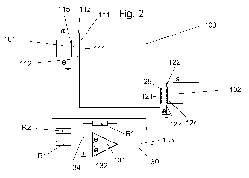
Fig. 2 shows an arrangement of a calorimeter according to a first embodiment
of the
invention. The calorimeter according to Fig. 2 comprises a container 100, a
first heat sink
101, a second heat sink 102. The container is thermally insulated, such that a
heat transfer
substantially occurs through the heat transducer elements 111, 121 between the
container
100 and the first heat sink 101 or the second heat sink 102.
The container can receive a sample volume of less than 500 microliters,
advantageously less
than 350 microliters, more preferred less than 200 microliters. For specific
applications, the
sample volume can be 1 microliter or less. Such a sample size may be required
for animal
healthcare. A possible field of application are for instance animal urinal
measurements. The
values, ranges of values, materials mentioned in this application are
exemplary. Equivalents,
alternatives, modifications, deviations apparent to the skilled person in the
art are
contemplated and considered to be comprised within the scope of the disclosed
invention.
For instance, the container can have a shape comprising at least one element
of the group
comprising a cylinder, a cone, a frustrum of a cone, a prism, a
parallelepiped, a pyramid, a
container of rectangular or square cross-section.
CA 03063295 2019-11-12
WO 2018/220153
PCT/EP2018/064411
The first heat sink 101 comprises a first heat transducer element 111
comprising a heat
receiving surface 114 facing the container wall and a heat absorbing surface
115. The first
heat transducer element 111 is disposed with electrical connectors 112. The
electrical
connectors 112 can comprise a positive connector 116 and a negative connector
117 as
shown in greater detail in Fig. 4. The first heat transducer element 111 can
comprise a stack
of p-n layers, thus layers including a p-type conductive material, and layers
including a n-
type conductive material, thereby forming a thermopile for instance as shown
in Fig. 6.
In this embodiment, the heat receiving surface 114 is arranged in proximity to
the wall of the
container 100, in particularly it can be in contact with the container wall.
The first heat
transducer element 111 receives or transmits a heat flux from/to the heat sink
101 through
the heat absorbing surface 115. The heat flux is transformed in the heat
transducer element
111 into an electric current, as a potential difference is generated between
the stack of p-n
conducting layers due to the energy supply from the heat flux. According to
this
embodiment, negative connector 117 is connected to earth as shown in detail in
Fig. 4. The
positive connector 116 is connected by an electrical conduit, such as wire, to
a resistor R1.
The second heat sink 102 is disposed with a first heat transducer element 121
comprising a
heat receiving surface 124 facing the second heat sink 102 and a heat
absorbing surface 125
facing the container wall. Advantageously, the heat absorbing surface 125 is
in contact with
the container wall. The second heat transducer element 121 is disposed with
electrical
connectors 122. The electrical connectors 122 can comprise a positive
connector 126 and a
negative connector 127 as shown in greater detail in Fig. 5. The second heat
transducer
element 121 can comprise a stack of layers including a p-type conductive
material, and
layers including a n-type conductive material, thereby forming a thermopile
for instance as
shown in Fig. 6.
In this embodiment, the heat absorbing surface 125 is arranged in proximity to
the wall of
the container 100, in particular, it can be in contact with the container
wall. The second heat
transducer element 121 receives or transmits a heat flux from/to the container
100 through
the heat absorbing surface 125. The heat flux is transformed in the second
heat transducer
element 121 into an electric current, as a potential difference is generated
between the stack
of layers including a p-type conductive material, and layers including a n-
type conductive
material due to the energy supply or energy drain from the heat flux.
According to this
embodiment, the positive connector 126 is connected to earth as shown in
detail in Fig. 4.
16
CA 03063295 2019-11-12
WO 2018/220153
PCT/EP2018/064411
The negative connector 127 is connected by an electrical conduit, such as
wire, to a resistor
R2.
The resistors R1 and R2 are arranged in parallel arrangement with respect to
each other.
Resistor R2 is connected to the negative connector 127 of the second heat
transducer
element 121 and resistor R1 is connected to the positive connector 116 of the
first heat
transducer element 111. For this reason, the first heat sink 101 is mounted in
an antiparallel
mounting with respect to the second heat sink 102. The output currents of
resistor R1 and
resistor R2 are collected and added in summing point 134. An electrical
conduit is provided
from the summing point 134 to a negative input 132 of an amplifier 130. The
combined
output current from summing point 132 is introduced through the electrical
conduit into the
amplifier 130 via the negative input 132. Due to the fact, that the current
leaving resistor R1
has the opposite direction as compared to the current leaving resistor R2, the
difference of
these two currents is obtained in the summing point 134. The resulting current
may be zero
Amperes, if the current from R1 and the current from R2 have the same absolute
value.
The ohmic resistance of each of resistors R1 or R2 is adjusted by calibration
as previously
mentioned, such that the non-zero Seebeck currents are canceled out.
Therefore, the
antiparallel mounting of the first and second heat sinks 101, 102 of the
calorimeter of the
invention results in an elimination of the non-zero Seebeck currents which
have to be dealt
with by any calorimeter according to the prior art. The resistor Rf is used in
the current to
voltage conversion of the amplification process.
The summing amplifier 130 generates an output voltage 135 which corresponds to
the heat
flux generated in container 100. The summing amplifier 130 comprises a
positive input 133,
which is connected to earth. The use of the summing amplifier 130 makes it
possible to
reliably detect very small heat flows, such as those emitted any type of
chemical reaction or
biological process or metabolism, e.g. by cell activity, pathogens or viruses,
funghi, bacteria.
The heat flux can be registered for a certain time period and may be
characteristic to a
certain phenomenon. Therefore, the location of the peaks in the heat flux
curve can be used
to detect the species of pathogens, cells, viruses, funghi or bacteria present
in the sample in
the container. Therefore, the calorimeter is not only useful to detect the
presence of an
energy source in the sample, it can be also useful also to determine the type
of heat source,
e.g. the species of pathogens, cells, viruses, funghi or bacteria responsible
for the heat
generation.
17
CA 03063295 2019-11-12
WO 2018/220153
PCT/EP2018/064411
The embodiment according to Fig. 3 differs from the previous embodiment in the
configuration of the first heat sink 101 with respect to the second heat sink
102. The first
heat sink 101 and the second heat sink 102 are arranged on the same side of
the container
100. In the embodiment of Fig. 3 the same reference numbers are used for the
same parts
as in Fig. 2. In the embodiment of Fig. 2 the first heat sink 101 is arranged
at a different side
of the container 100 with respect to the second heat sink 102. According to
the embodiment
of Fig. 3 the first heat sink 101 is arranged on the same side of the
container as the second
heat sink 102.
Fig. 4 shows a detail of the first heat sink 101 including the first heat
transducer element 111
according to the invention. The heat transducer element 111 comprises a heat
absorbing
surface 115. The first heat sink 101 is in contact with the heat absorbing
surface 115 so to
allow for a heat transfer from the heat sink 101 to the first heat transducer
element 111.
The first heat transducer element 111 comprises a heat receiving surface 114.
The heat
receiving surface 114 is in contact with a wall of the container 100. The heat
receiving
surface 114 and the heat absorbing surface 115 are configured as a thermally
conductive
electric insulator 113. A stack layers including a p-type conductive material
and layers
including a n-type conductive material is arranged between the heat absorbing
surface 115
and the heat receiving surface 114 so as to transform e.g. the heat flux from
the heat
absorbing surface 115 to the heat receiving surface 114 into an electric
current. The two
outermost conductors are connected to end connectors 116, 117 leading to an
electrical
conduit. The end connector 116 is a positive connector, the end connector 117
is a negative
connector. In Fig. 4 the negative connector 117 is connected to earth.
The container wall can have any orientation in space, the orientation is not
limited to the
.. vertical arrangement as shown in Fig. 4. This means that the first heat
transducer element
111 can be attached to a vertical container wall, an inclined wall or a
horizontal container
wall, for instance a container bottom wall.
Fig. 5 shows a detail of the second heat sink 102 including the second heat
transducer
element 121 according to the invention. The heat transducer element 121
comprises a heat
absorbing surface 125. The second heat transducer element 121 comprises a heat
receiving
surface 124. The second heat sink 102 is in contact with the heat receiving
surface 124 so to
allow for a heat transfer from the second heat transducer element 121 to the
heat sink 102.
The heat absorbing surface 125 is in contact with a wall of the container 100.
The heat
receiving surface 124 and the heat absorbing surface 125 are configured as a
thermally
18
CA 03063295 2019-11-12
WO 2018/220153
PCT/EP2018/064411
conductive electric insulator 123. A stack of layers including a p-type
conductive material and
layers including a n-type conductive material is arranged between the heat
absorbing surface
125 and the heat receiving surface 124 so as to transform the heat flux from
the heat
absorbing surface 125 to the heat receiving surface 124 into an electric
current. The two
outermost conductors are connected to end connectors 126, 127 leading to an
electrical
conduit. The end connector 126 is a positive connector, the end connector 127
is a negative
connector. In Fig. 5 the positive connector 126 is connected to earth.
Fig. 6 shows an example of a heat transducer element 21 which can be the same
as the first
and second heat transducer elements 111, 121 used in the previous embodiments.
The heat
transducer element thereby operates as a heat-flow sensor. The heat transducer
element is
an electromotive force (emf) producing element being disposed with an internal
resistor R. It
transforms the heat-flow into electric power (voltage and/or current). By
placing the
detecting unit including all electrical conduits within the temperature
stabilized space of the
calorimeter any temperature dependent effects of any of the components forming
the
detecting unit can be eliminated. The heat transducer element 21 comprises a
heat receiving
surface 24 and a heat absorbing surface 25. The heat receiving surface 24 and
the heat
absorbing surface can be in contact with a wall of the container 100 or with a
heat sink such
as the heat sinks 101, 102 of any of Fig. 2-5.
The heat receiving surface 24 and the heat absorbing surface 25 comprise a
thermally
conductive electric insulator 23. A stack of layers including a p-type
conductive material, and
layers including a n-type conductive material is arranged between the heat
absorbing surface
and the heat receiving surface 24 so as to transform the heat flux from the
heat
25 absorbing surface 25 to the heat receiving surface 24 into an electric
current. The layer
including a p-type conductive material and the layer including a n-type
conductive material
are advantageously arranged in an alternate arrangement in a stack, thus a
layer including a
p-type conductive material is followed by a layer including a n-type
conductive material and
vice versa. The layer including a p-type conductive material 28 and the layer
including a n-
type conductive material 29 are connected by electric connectors 22 in such a
way that the
layer including a p-type conductive material 28 is always connected to a layer
including a n-
type conductive material 29 and a layer including a n-type conductive material
29 is always
connected to a layer including a p-type conductive material 28. The two
outermost
conductors 22 are connected to end connectors 26, 27 leading to an electrical
conduit. When
operated as a sensor an applied heat-flux from the heat absorbing surface 25
to the heat
19
CA 03063295 2019-11-12
WO 2018/220153
PCT/EP2018/064411
receiving surface 24, the heat absorbing surface 25 is heated and the heat
receiving surface
24 is cold, thereby a negative current is generated. A positive current is
obtained if the
heatflow is reversed.
When operated as a Peltier element, an applied positive current generates a
heat-flow from
heat absorbing surface 25 to heat receiving surface 24, thereby it cools the
heat absorbing
surface 25.
According to a further embodiment, the heat transducer element can be
configured as a
thermistor. The thermistor may include a semiconductor material, e.g. a
metallic oxide of
manganese, nickel, cobalt, copper, uranium, iron, zinc, titanium, barium,
magnesium. The
temperature coefficient is determined by the properties of oxides in the
mixture. The
thermistor comprises a bead or rod and the first and second electrically
conductive surfaces
may be configured as electrical leads, in particular bifilar leads including
an electrically
conductive material, such as copper.
It should be apparent to those skilled in the art that many more modifications
besides those
already described are possible without departing from the inventive concepts
herein. The
inventive subject matter, therefore, is not to be restricted except in the
scope of the
appended claims. Moreover, in interpreting both the specification and the
claims, all terms
should be interpreted in the broadest possible manner consistent with the
context. In
particular, the terms "comprises" and "comprising" should be interpreted as
referring to
elements, components, or steps in a non-exclusive manner, indicating that the
referenced
elements, components, or steps may be present, or utilized, or combined with
other
elements, components, or steps that are not expressly referenced. Where the
specification
claims refers to at least one of an element or compound selected from the
group consisting
of A, B, C .... and N, the text should be interpreted as requiring only one
element from the
group, not A plus N, or B plus N, etc.