Note : Les descriptions sont présentées dans la langue officielle dans laquelle elles ont été soumises.
CA 03063591 2019-11-13
WO 2018/212993 PCT/US2018/030566
TERMINAL BOX APPARATUS WITH SIDE WALL ENTRANCE
AND CURVED WIRING GUIDE
FIELD OF THE DISCLOSURE
[0001] This disclosure relates generally to electrical connection apparatus
and, more
particularly, to terminal box apparatus with side wall entrance and a curved
wiring guide.
BACKGROUND
[0002] Process control systems typically require a large amount of wiring to
transfer
information and provide electrical power. The field devices used in process
control systems
often require multiple wires to terminate at a single location. Terminal boxes
generally have a
housing including a base and a removable cover to access wiring terminals
within the
terminal box, as well as an entryway to allow wires into the housing. The
wiring terminals are
usually positioned toward the top of the terminal box and the entryway resides
on the side
wall of the housing. As a result, the wires enter a side wall of the housing,
bend at
approximately a right angle, and travel upward toward the wiring terminals.
SUMMARY
[0003] An example terminal box disclosed herein includes a housing having a
base, a
side wall extending from the base, and a first opening opposite the base to
provide access to
wiring terminals to be mounted adjacent an inner surface of the side wall. The
terminal box
further includes a second opening in the side wall, the second opening
providing access to a
curved wiring guide within the housing, the curved wiring guide shaped to
guide electrical
wires away from the base and toward a central portion of the first opening.
[0004] Another example terminal box disclosed herein includes a housing having
a
base, a wall extending from the base, and a first opening in the wall. The
first opening
provides access to a curved wiring guide within the housing, the curved wiring
guide shaped
to guide electrical wires away from the base.
Yet another example terminal box disclosed herein includes a curved wiring
guide
including two openings at opposite ends of the curved wiring guide. The two
openings have
respective central axes that are approximately perpendicular. The terminal box
further
includes at least one mount on an outer surface of the curved wiring guide to
couple to a
- 1 -
CA 03063591 2019-11-13
WO 2018/212993 PCT/US2018/030566
terminal block, the terminal block including wiring terminals, the wiring
terminals to make
electrical connections with wires traveling through the curved wiring guide.
BRIEF DESCRIPTION OF THE DRAWINGS
[0005] FIG. 1 illustrates an example terminal box with two example side wall
entrances in accordance with the present disclosure.
[0006] FIG. 2 illustrates a cross-sectional view of the example terminal box
of FIG. 1.
[0007] FIG. 3 illustrates another cross-sectional view of the example terminal
box of
FIGS. 1 and 2.
[0008] FIG. 4 illustrates the example wiring guide used within the terminal
box of
FIGS. 1 ¨ 3.
[0009] FIG. 5 illustrates another example terminal box with a rectangularly
shaped
housing.
[0010] The figures are not to scale. Instead, to clarify multiple layers and
regions, the
thickness of the layers may be enlarged in the drawings. Wherever possible,
the same
reference numbers will be used throughout the drawing(s) and accompanying
written
description to refer to the same or like parts. As used in this patent,
stating that any part (e.g.,
a layer, film, area, or plate) is in any way positioned on (e.g., positioned
on, located on,
disposed on, or formed on, etc.) another part, means that the referenced part
is either in
contact with the other part, or that the referenced part is above the other
part with one or more
intermediate part(s) located there between. Stating that any part is in
contact with another
part means that there is no intermediate part between the two parts.
DETAILED DESCRIPTION
[0011] Terminal boxes are commonly used in process control systems to
distribute
power and other signals to various field devices via wires and wiring
terminals within the
terminal boxes. In some examples, field devices require multiple wires to
terminate or
connect at a single location. In such examples, terminal boxes may be used to
house these
connections. Known terminal boxes typically have a housing with an entryway or
opening
through a side wall into the terminal box. The wiring terminals are typically
adjacent an
opening toward the top of the terminal box. These known designs typically
require wires to
enter the terminal box horizontally through the side wall, bend at
approximately a right angle,
and travel vertically up toward the wiring terminals. This may cause a sharp
bend in the
- 2 -
CA 03063591 2019-11-13
WO 2018/212993 PCT/US2018/030566
wires, which may cause a loss of connection, frayed wires, or difficulty
routing the wires
through the terminal box.
[0012] Example terminal boxes disclosed herein provide an entryway or opening
on
the exterior side wall of the housing leading into a curved wiring guide. The
shape of the
wiring guide allows the wires to reach the wiring terminals with significantly
less bending
than the above-noted known designs.
[0013] In an example terminal box disclosed herein, the housing includes a
base, a
peripheral side wall extending from the base, and a first opening opposite the
base to provide
access to wiring terminals. The housing further includes a second opening in
the side wall
that provides access to a curved wiring guide within the housing. The curved
wiring guide is
shaped to guide electrical wires away from the base and toward a central
portion of the first
opening. The first opening and the second opening have central axes that are
approximately
perpendicular.
[0014] In an additional example terminal box described herein, the housing
includes a
base, an outer side wall extending from the base, and a first opening opposite
the base to
provide access to wiring terminals. The housing further includes second and
third openings
through the side wall that may or may not be spaced evenly or in another
manner around the
side wall. For example, the second and third openings through the housing of a
terminal box
may be positioned 180 degrees from one another, 90 degrees from one another,
etc. The
second and third openings provide access to a curved wiring guide within the
housing. The
curved wiring guide is shaped to guide electrical wires away from the base and
toward a
central portion of the first opening. In some examples, a terminal box housing
may include
more than two entryways or openings through the side wall.
[0015] FIG. 1 illustrates an example terminal box 100 including a housing 101
that
includes a peripheral side wall 102, a base 103 and a first opening 104
opposite the base 103.
The first opening 104 provides access to a curved wiring guide 105 that is
shaped to guide
wires toward a central portion of the first opening 104. The housing 101
further includes a
second opening 106 through the side wall 102 that has a central axis 107 and a
third opening
108 through the side wall 102 that has a central axis 109. In this example
terminal box, an
angle 110 between the central axes 107 and 109 is approximately ninety
degrees. However, in
other examples, the angle 110 may be wider or narrower. Further, in the
illustrated example,
the terminal box 100 has two openings through the side wall 102. However, in
other
examples, the number of openings may be greater or fewer.
- 3 -
CA 03063591 2019-11-13
WO 2018/212993 PCT/US2018/030566
[0016] The second and third openings 106 and 108 include respective threads
111 and
112, to receive conduit connections. The second and third openings 106 and 108
lead into the
curved wiring guide 105. In the illustrated example, the curved wiring guide
105 includes
two curved passageways, 114 and 116. As more clearly depicted in FIGS. 2 - 4,
the example
curved passageways 114 and 116, are elbow shaped. The curvature of the
passageways 114
and 116 allows the wires to reach the wiring terminals 202 (shown in FIG. 2)
without
excessive bending. The passageways 114 and 116, lead to an interior opening
118. As
shown, the second and third openings 106 and 108 and the interior opening 118
are at
opposite ends of the curved wiring guide 105. In the illustrated example, the
curved
passageways 114 and 116 are positioned such that the second opening 106 and
the interior
opening 118 at an end of the curved passageway 114 adjacent the first opening
104 each have
respective central axes, 107 and 119 that are approximately perpendicular.
Similarly, the
interior opening 118 and the third opening 108 have respective central axes,
119 and 109 that
are approximately perpendicular. Further, while the illustrated example
terminal box 100
includes two curved passageways, in other examples, the number of curved
passageways may
be greater or fewer.
[0017] Adjacent to the interior opening 118 are three mounts 120 on the outer
surface
of the curved wiring guide 105 to receive a terminal block 206 (shown in FIG.
2) containing
wiring terminals. A fourth mount 121 resides on the outer surface of the
curved wiring guide
105 to receive a ground wiring terminal. To house the three mounts 120, the
fourth mount
121, and the terminal block, the outer surface of the housing 101 adjacent the
first opening
104 includes threads 122 to receive a threaded cover.
[0018] The housing 101 further includes a mounting boss 124 with holes 126 to
allow
the terminal box 100 to be mounted to electrical equipment, a field device,
etc. In the
illustrated example, a fourth opening 128 through the side wall 102 provides a
passageway
that may be used to provide access to a circuit board 208 (shown in FIG. 2).
The mounting
boss 124 and the openings 106 and 108 include multiple recesses 130 to secure
the threaded
cover to the housing 101, prevent loosening of the cover, and satisfy
explosion-proof
requirements.
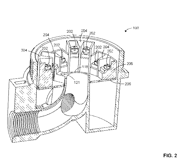
[0019] FIG. 2 illustrates a cross-sectional view of the example terminal box
100
including wiring terminals 202 coupled to compartments 204 that are attached
to a terminal
block 206. The compartments 204 and the terminal block 206 serve as a place to
hold the
wiring terminals 202. FIG. 2 further illustrates a circuit board 208
supporting the terminal
- 4 -
CA 03063591 2019-11-13
WO 2018/212993 PCT/US2018/030566
block 206. The circuit board 208 may be attached to the terminal box 100 via
the mounts 120
(shown in FIG. 1). For example, fasteners may pass through the circuit board
208 into the
mounts 120. The wiring terminals 202 in the example terminal box 100 are screw
terminals.
However, in other examples, the wiring terminals 202 may be any type of
terminal
connection (e.g., clip, tongue, crimp, tab, etc.). FIG. 2 also clearly shows
the fourth mount
121 to accept a ground wiring terminal adjacent the interior opening 118. The
fourth mount
121 may be electrically connected to the circuit board 208 and/or the housing
101 of the
terminal box 100.
[0020] FIG. 3 illustrates another cross-sectional view of the example terminal
box
100 without the terminal block 206. FIG. 3 clearly illustrates the shape of
the curved
passageway 116 within the curved wiring guide 105. The example curved wiring
guide 105
may be attached to the housing 101 after the manufacture of both parts, or the
curved wiring
guide 105 may be integrally molded within the housing 101. Additionally, FIG.
3 shows a
ground wire 302 traveling through the curved wiring guide 105 and through the
interior
opening 118. The ground wire 302 connects to the ground wiring terminal 304
mounted on
an outer surface of the curved wiring guide 105 adjacent the interior opening
118. In the
illustrated example, the ground wiring terminal 304 is attached to an outer
surface of the
curved wiring guide 105. However, in other examples, the ground wiring
terminal 304 may
be coupled to the inner surface of the housing 101 or any other place on the
terminal box.
FIG. 3 further illustrates the threads 112 on the inner surface of the third
opening 108. The
threads 112 allow the wiring guide 105 to receive a conduit connection. This
view of the
example terminal box 100 also illustrates the threads 122 adjacent the first
opening 104.
These threads 122 allow the terminal box 100 to receive a threaded cover.
[0021] FIG. 4 illustrates the example curved wiring guide 105 that may be used
within the example terminal box 100. As shown, the central axis 119 is
approximately
perpendicular to both central axes 107 and 109. FIG. 4 also shows two of the
mounts 120 to
couple to a terminal block on the outer surface of the wiring guide 105.
Although the
example wiring guide 105 includes three mounts 120 to couple to a terminal
block, in other
examples, the number of mounts 120 may be greater or fewer.
[0022] FIG. 5 illustrates another example terminal box 500. The terminal box
500
has a rectangularly shaped housing 501 and an opening 502 to provide access to
the wiring
guide 105. The example terminal boxes 100 and 500 disclosed herein have
respective
- 5 -
CA 03063591 2019-11-13
WO 2018/212993 PCT/US2018/030566
housings 101 and 501 that are cylindrically and rectangularly shaped. However,
in other
examples, a terminal box may include a housing having a different shape.
[0023] Although certain example methods, apparatus and articles of manufacture
have been disclosed herein, the scope of coverage of this patent is not
limited thereto. On the
contrary, this patent covers all methods, apparatus and articles of
manufacture fairly falling
within the scope of the claims of this patent.
- 6 -