Note : Les descriptions sont présentées dans la langue officielle dans laquelle elles ont été soumises.
UNIVERSAL POWER CONVERTER
CROSS-REFERENCE TO RELATED APPLICATIONS
[0001] This application is a non-provisional and claims the benefit of U.S.
Prov. Pat. App.
Ser. No. 62/508,282, entitled "Universal Power Converter," filed May 18, 2017.
BACKGROUND
[0002] AC-AC power converters allow for flexible output power control in a
variety of
applications. Traditionally, power control for many AC loads is performed by
duty cycle
switching algorithms, which essentially skip entire line cycles, therefore
regulating the output
power without changing the peak output voltage. Presently, there exist
solutions for AC-AC
converters in the kW range. However, these solutions rely on an input
switching stage, tank
storage (such as in resonant converters), as well as an output switching stage
(or inverter), and
some solutions rely on a DC link. Implementing this solution in a "hazardous"
area becomes
costly and difficult. All of the existing solutions that both operate in the
kW range and are
commercially affordable rely on the use of an internal cooling fan, and such
cooling fans are
prohibited for use in power converters in hazardous areas. Specifically, the
industrial heat
tracing market does not allow for cooling fans in power converters in many
crucial
applications. Extending the present solutions for AC-AC converters with dialed-
in peak
voltage to heat tracing applications and hazardous area applications therefore
becomes very
costly.
[0003] Existing power converters are costly and many do not meet the
requirements for
use in the hazardous areas, and specifically for use in industrial heating
tracing applications.
Therefore what is needed is an improved power converter for use in hazardous
areas.
SUMMARY
[0004] The preceding needs are met via the presently disclosed universal
power converter
configured for use in hazardous areas or non-hazardous areas. Embodiments of
the invention
provide an AC-AC power converter which produces AC power in the kilowatt range
and
controls the peak output voltage, while maintaining the substantially
sinusoidal waveform
required by many AC loads.
1
Date Recue/Date Received 2023-05-31
CA 03063970 2019-11-18
WO 2018/211334 PCT/1B2018/000797
[0005] In one embodiment, a power converter for heat tracing applications
is disclosed. The
power converter includes a controller configured to control an input switching
stage. The power
converter also includes an output filter, the output filter electrically
coupled to the input
switching stage. Further, the power converter includes a passive cooling
element, the passive
cooling element coupled to the power converter. The controller is configured
to select a peak
voltage and set a power converter output voltage based on at least one of the
peak voltage and a
power converter input voltage. The passive cooling element is configured to
decrease a
temperature of the power converter. The input switching stage includes a
plurality of solid-gate
switches such as MOSFETs, IGETs or other transistors. The power converter
output voltage and
the power converter input voltage comprise alternating current (AC).
[0006] The passive cooling element may be a heat sink, such that the power
converter is not
cooled by a cooling system with moving parts, enabling operation of the power
converter in
hazardous areas. The output filter may include at least one of a resistor, a
capacitor, and an
inductor; the inductor may be configured to optimize an efficiency of the
power converter. The
power converter may be further configured for use with: a plurality of self-
regulating heaters,
each of the plurality of self-regulating heaters configured for a different
power rating; and/or, a
plurality of mineral-insulated heating cables each having a different cable
input voltage, the
controller controlling the input switching stage based on the power converter
input voltage to
produce, as the power converter output voltage, any of the different cable
input voltages.
[0007] In another embodiment, an AC-AC power converter is disclosed. The AC-
AC power
converter includes a controller, the controller configured to control an input
switching stage.
Additionally, the AC-AC power converter includes an output filter, the output
filter electrically
coupled to the input switching stage. Further, the AC-AC power converter
includes a heat sink,
the heat sink coupled to the AC-AC power converter. The controller is
configured to set a peak
output voltage of the AC-AC power converter. The heat sink is configured to
cool the AC-AC
power converter. The input switching stage may include a full-bridge input
switching stage, and
the output filter may include a plurality of passive electrical components.
[0008] The heat sink may be sized so as to avoid the need for a cooling fan
and any other
cooling system with moving parts, enabling operation of the AC-AC power
converter in
2
hazardous areas. The full-bridge input switching stage may include a plurality
of insulated-
gate bipolar transistors (IGBT), the input switching stage configuring the AC-
AC power
converter as a Buck converter. The passive electrical components of the output
filter may
include at least one of a resistor, a capacitor, and an inductor; for example,
the output filter
may include a capacitor and an inductor electrically connected to the
capacitor to form an LC
filter. The controller may enable an operating range of the AC-AC power
converter of lkW to
60kW, and may configure the power converter for use with: a plurality of
mineral-insulated
heating cables each having a different cable input voltage, the controller
controlling the input
switching stage based on the power converter input voltage to produce, as the
power converter
output voltage, any of the different cable input voltages; and/or, a plurality
of self-regulating
heaters, each of the plurality of self-regulating heaters configured for a
different power rating.
[0008A] In another embodiment, a power converter for heat tracing applications
comprises
a controller configured for use with a plurality of mineral-insulated heating
cables, with each
individual cable in the plurality of mineral-insulated heating cables having a
different cable
input voltage. The controller is configured to control an input switching
stage comprising a
plurality of transistors. It is further configured to select a peak voltage,
and set a power
converter output voltage based on at least one of the peak voltage and a power
converter input
voltage. The power converter output voltage and the power converter input
voltage comprise
alternating current (AC) and the power converter output voltage is any of the
different cable
input voltages. The controller controls the input switching stage based on the
power converter
input voltage to produce the power converter output voltage. The power
converter further
comprises an output filter is electrically coupled to the input switching
stage, and a passive
cooling element coupled to the power converter to decrease a temperature of
the power
converter.
[000813] In another embodiment, an AC-AC power converter comprises an input
switching
stage, and a controller configured for use with a plurality of mineral-
insulated heating cables.
Each individual cable in the plurality of mineral-insulated heating cables has
a different cable
input voltage, and the controller is configured to control the input switching
stage producing
an output voltage of the AC-AC power converter at any of the different cable
input voltages
and causing a desired peak output voltage of the AC-AC power converter. The
converter
further comprises an output filter electrically coupled to the input switching
stage and
3
Date Recue/Date Received 2023-05-31
comprising a plurality of passive electrical components; and a heat sink
passively cooling the
AC-AC power converter.
[0008C] In another embodiment, a power converter for heat tracing applications
comprises
an input switching stage, and a controller in electrical communication with
the input switching
stage and configured for use with a plurality of mineral-insulated heating
cables. Each
individual cable in the plurality of mineral-insulated heating cables has a
different cable input
voltage. The controller is configured to determine a peak voltage of a desired
alternating
output current produced by the power converter. The controller is further
configured to
determine a power converter input voltage from an alternating input current
provided to the
power converter by an alternating current (AC) source, and to control the
input switching
stage based on one or both of the peak voltage and the power converter input
voltage to cause
the power converter to produce the alternating output current with a power
converter output
voltage selected from the different cable input voltages.
DESCRIPTION OF THE DRAWINGS
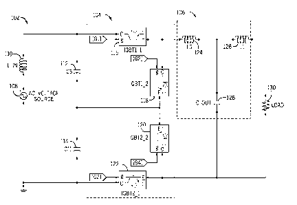
[0009] FIG, 1 is a circuit-level schematic of an embodiment of a universal
power
converter in accordance with the present disclosure;
[0010] FIG. 2 A is a circuit-level schematic of another embodiment of a
universal power
converter in accordance with the present disclosure;
[0011] FIG. 2B is a waveform diagram showing operation of the universal
power
converter of FIG. 2A in accordance with the present disclosure;
[0012] FIGS. 3A-3B illustrate a physical representation of another
embodiment of a
universal power converter in accordance with the present disclosure;
[0013] FIG. 4 is a high-level block diagram of an embodiment of a zero-
crossing
controller in accordance with the present disclosure; and
[0014] FIG. 5 is a simulated output in relation to the zero-crossing
controller of FIG. 4 in
accordance with the present disclosure.
[0015] FIG. 6 is a plot of measured input and output of an embodiment of
the AC-AC
power converter described herein.
3A
Date Recue/Date Received 2023-05-31
CA 03063970 2019-11-18
WO 2018/211334 PCT/1B2018/000797
DETAILED DESCRIPTION
[0016] Before any embodiments of the invention are explained in detail, it
is to be
understood that the invention is not limited in its application to the details
of construction and the
arrangement of components set forth in the following description or
illustrated in the following
drawings. The invention is capable of other embodiments and of being practiced
or of being
carried out in various ways. Also, it is to be understood that the phraseology
and terminology
used herein is for the purpose of description and should not be regarded as
limiting. The use of
"including," "comprising," or "having" and variations thereof herein is meant
to encompass the
items listed thereafter and equivalents thereof as well as additional items.
Unless specified or
limited otherwise, the terms "mounted," "connected," "supported," and
"coupled" and variations
thereof are used broadly and encompass both direct and indirect mountings,
connections,
supports, and couplings. Further, "connected" and "coupled" are not restricted
to physical or
mechanical connections or couplings.
[0017] The following discussion is presented to enable a person skilled in
the art to make and
use embodiments of the invention. Various modifications to the illustrated
embodiments will be
readily apparent to those skilled in the art, and the generic principles
herein can be applied to
other embodiments and applications without departing from embodiments of the
invention.
Thus, embodiments of the invention are not intended to be limited to
embodiments shown, but
are to be accorded the widest scope consistent with the principles and
features disclosed herein.
The following detailed description is to be read with reference to the
figures, in which like
elements in different figures have like reference numerals. The figures, which
are not necessarily
to scale, depict selected embodiments and are not intended to limit the scope
of embodiments of
the invention. Skilled artisans will recognize the examples provided herein
have many useful
alternatives and fall within the scope of embodiments of the invention,
[0018] Embodiments of the present disclosure provide a system and a method
for an AC-AC
converter for use in heat tracing applications, self-regulating heaters,
constant wattage heaters,
and other heating applications. Additional embodiments of the present
disclosure provide a
system and a method for an AC/DC, DC/AC, DC/DC, or any other combination of
converter, for
4
CA 03063970 20193.1-3.9
WO 2018/211334
PCT/M2018/000797
use in heat tracing applications, self-regulating heaters, constant wattage
heaters, and other
heating applications.
[0019] FIG. 1 is a schematic of a power converter 102 in accordance
with the present
= disclosure. The power converter 102 may be or include a customized Buck
converter. The
power converter 102 may include an input switching stage 104 as well as an
output filter 106.
An AC voltage source 108 may be provided in series with an inductor 110.
Capacitors 112, 114
may be included within the power converter 102. The input switching stage 104
may include a
plurality of transistors 116, 118, 120, 122. The transistors 116-122 may be
arranged to establish
a full-bridge input switching stage. The plurality of transistors 116-122 may
include an insulated
gate bipolar transistor (IOBT), a MOSFET, a silicon (Si) transistor, a silicon
carbide (SIC)
transistor, a gallium nitride (GaN) transistor, or any other element capable
of switching
functionality. The input switching stage 104 may be connected to the output
filter 106. The
output filter may include a plurality of passive electrical components. hi.
certain situations, it
may be beneficial to have an output filter 6 that includes an output inductor
124 and output
capacitor 126 arranged to establish an LC filter. Additional passive
components such as inductor
128 may be included in the power converter 102. Via the power converter 102, a
load 130 (e.g.,
a heater cable as described herein) is supplied with a controlled voltage.
[0020] Still referring to FIG. 1, the power converter 102 may allow
for a transformer-less
voltage supply based on switching high frequency and high current transistors
with intennittent
energy storage in passive inductive and capacitive circuit elements. The
output from the power
converter 102 may be a sinusoidal AC waveform with a predetermined and
selectable peak
voltage. In some situations, it may be beneficial to use insulated-gate
bipolar transistors (IGBT)
for transistors 116-122. In some situations, it may be beneficial to use
silicon carbide (SiC) for
transistors 116-122. The predetermined and selectable peak voltage may have a
wide range of
possible selections. In some embodiments, the peak voltage may be selected
from a range of
120V - OV. In other embodiments, the peak voltage may be selected from a range
of 230V - OV.
In other embodiments, the peak voltage may be selected from a range or 85V -
600V.
Alternatively, the peak voltage may be selected from any additional range of
voltages. Power
converter 102 may produce a selectable peak voltage without the use of tap
transformers, which
can be very costly. In some embodiments, the output from the power converter
102 may be
CA 03063970 2019-11-18
WO 2018/211334 PCT/M2018/000797
50Hz. In some embodiments, the output. from the power converter 102 may be
60Hz. In certain
embodiments, the output from the power converter 102 may have a frequency
within the range of
Illz to 100 kHz. Alternatively, the frequency may be selected from any
additional range of
frequencies.
[0021] The power converter 102 may use passive cooling. The passive cooling
may be
performed via heat sinks within the power converter 102. Alternatively, the
passive cooling may
be performed via liquid cooling within the power converter 102. Utilizing
passive cooling
methods may enable power converter 102 to be used in applications that
specifically do not
allow cooling fans. One non-limiting example of this is the potential use of
power converter 102
in industrial heat tracing applications and hazardous environments where spark-
producing
electronics, such as motorized cooling systems, are not permitted. Further,
the power converter
102 may be used with self-regulating heaters. The power converter 102 may also
be used with
constant wattage heaters. One non-limiting example of such a constant wattage
heater is
Mineral-Insulated (MI) cables.
[0022] By selecting the peak voltage via the power converter 102, the
number of different
wattage ratings offered for self-regulating heaters cables maybe consolidated.
This differentiates
the power converter 102 from the present market reality, where we desire
different wattage
output ratings, but have only one or few line voltages available. Further, the
power converter 102
may enable the soft-start ¨ defined as slowly ramping up the AC voltage from a
lower range to
the final range ¨ of self-regulating heaters to avoid de-rating of circuit
breakers for inrush
situations,
[0023] At present, MI cables are either custom-manufactured for a given
circuit length and
available line voltage, or a very wide range of different MI cables need to be
kept in inventory to
satisfy the needs of the market. This is due to the present inability to dial
in different voltages to
supply MI cables. By selecting the peak voltage via the power converter 210,
the wattage output
of MI cables may be regulated to a desired or specified value, which may
enable MI cables to
evolve from custom-manufactured cables for a given wattage output based on
fixed line voltages,
to power output to a greater degree determined by the voltage.
6
CA 03063970 2019-11-18
WO 2018/211334 PCT/1B2018/000797
[0024] FIG. 2A shows another non-limiting example embodiment of a power
converter 202
as a simplified Buck Converter model. The AC source 208 may power the
transistors 216, 218,
220, 222. The AC source 208 may be in series with the inductor 210. A
capacitor 213 may be
connected in parallel with the series combination of the AC source 208 and the
inductor 210.
The output inductor 224 and the output capacitor 226 may be included in the
power converter
202. The load 230 may additionally be included. Here, transistor 216 is
associated with Si,
transistor 218 is associated with S2, transistor 220 is associated with SA,
and transistor 222 is
associated with S4. FIG. 2B shows simulation results corresponding to the
embodiment shown in
FIG. 2A, The AC source 208 input is shown by waveform 215. The switching of
transistor 216
is shown by waveform 217 and the switching of transistor 220 is shown by
waveform 219. One
full-bridge input switching stage may be implemented, where switching as half-
bridge occurs
during each half-cycle. As shown, faster St/S2 switching may occur during
positive input
polarity, and faster S3/S4 switching during negative input polarity. The power
converter output
voltage may be controlled through duty cycle control, In one non-limiting
embodiment,
switching transistors may comprise two half-bridge-IGBT modules. In another
non-limiting
embodiment, switching transistors may comprise four single-IGBT modules. In
certain
situations, it may be beneficial to use EMI/RH suppression film capacitors, as
they may perform
better when compared with electrolytic capacitors.
[0025] Referring now to FIG. 3A-3B, another example embodiment of the power
converter
302 is shown. FIG. 3A shows an outside view of the power converter 302, which
may
implement any of the above-described electrical circuits. The power converter
302 may include
a housing 332. Additionally, the power converter 302 may include an AC source
input 334 and a
power switch 336. FIG. 3B shows the inside of the housing 332. The power
converter 302 again
may include passive elements such as output capacitor 326 and output inductor
324. The power
converter 302 may also include the input switching stage. In certain
embodiments, it may be
beneficial to have the input switching stage include a plurality of IGBTs 304,
The output
inductor 324 may be optimized specifically for efficiency purposes. As shown
by FIG. 3B, the
power converter 302 may include a controller 338. The controller 338 may be
used to control
the power converter output voltage. The controller 338 may be able to control
voltages at
efficiencies of 90%. Alternatively, the controller 338 may be able to control
voltages at
efficiencies above and below 90%.
7
CA 03063970 2019-11-18
W02018/211334 = PCT/M2018/000797
[0026] Referring to FIG. 4, a high-level block diagram for one embodiment
of a power
converter 402 is shown. FIG. 4 demonstrates how a controller 438 as described
above may be
included within (i.e., as a component of) the AC-AC power converter 402. A
zero-crossing
detector circuit 440 is designed to detect input sinewave zero-crossing and
polarity of the
sinewave. The input may be a sine wave, a square wave or basically any
waveform. The AC
voltage source 408 may be connected to the zero-crossing detector circuit 440,
which in some
embodiments may be a system of optocouplers. The system of optocouplers may
include a
unidirectional optocoupler 450 and a bidirectional optocoupler 452. The output
of the
optocouplers 450, 452 may go to a Schmitt-Trigger 442 to have sharp-edge
square waves;
additionally or alternatively, the voltage can be controlled to have a logic
output (high and low).
An output of the Schmitt-Trigger 442 may be connected to the controller 438.
The controller
438 may be connected to a plurality of optocouplers 444. The optocouplers 444
may be
connected to another Schmitt-Trigger 446. An output of the Schmitt-Trigger 446
may õbe
connected to a buffer 448. The buffer 448 may include a plurality of
capacitors. An output of
the buffer 448 may be connected to the input switching stage 404. As
previously stated, the
input switching stage 404 may include a plurality of transistors, as referred
to in FIGS. l and 2A.
[0027] The theoretical logic of the zero-crossing detector circuit is shown
by Table I:
P (tinidlreCtiOnal output) q (bldireCtierill
otitiitit) " . intiut siriewaiie situatio- '''''''''''''''''''
: ...........................................
0 0 1Zerocross1ng
0 1 . Negative (180 to 360
degree)
=== __ =
1 erret.rrnyva ARV, A AASA
0 N/A or zero-crossing
.=
: 1 1 ....................... Positive (0 to 180
degree)
TABLE I: Zero Crossing Detector Logic
Referring to Table I, a logical low is represented by a 0. A logical high is
represented by a I. A
logical high may indicate a positive voltage, such as 3.3V, 5V, or another
voltage.
[0028] FIG. 5 shows simulated results of a zero-crossing circuit designed
in accordance with
Table 1. The sine wave 502 represents the voltage of the AC input power. The
output of the
bidirectional optocoupler is shown as Wave 504, which is zero only at the zero-
crossings of the
8
sine wave 502, and is high (i.e., positive voltage) all other times (except
for transition periods
between zero and high). The output of the unidirectional optocoupler is shown
as wave 506,
which is high when the input voltage is positive and zero when the input
voltage is negative,
transitioning between zero and high states at the zero-crossings of the sine
wave 502; wave 506
overlaps wave 504 when the input voltage is positive and both optocouplers are
outputting a high
signal. FIG. 6 shows a set of actual results of the input and output sides of
the above-described
example AC-AC converter, at a 60% duty cycle and a load of 16.5 ohms. The
noisy sine wave
602 represents the voltage of the AC input power; the relatively clean sine
wave 604 represents
the voltage of the AC output power; and, sine wave 606 represents the output
current, in ohms.
[0029] It
will be appreciated by those skilled in the art that while the invention has
been
described above in connection with particular embodiments and examples, the
invention is not
necessarily so limited, and that numerous other embodiments, examples, uses,
modifications and
departures from the embodiments, examples and uses are intended to be
encompassed.
9
Date Recue/Date Received 2023-09-07