Note : Les descriptions sont présentées dans la langue officielle dans laquelle elles ont été soumises.
Sewer Back-flow Preventer Monitor
Description
1. This invention is electro-mechanical. It involves electrical feedback of
a
mechanical device and falls under the CPC section H. It attaches to a sewer
back-
flow preventer valve, otherwise known as a backwater valve, made by others.
2. Due to an intense storm causing flooding in our area, we experienced a
municipal sewer back-flow into the basement of our primary residence as well
as an
equal back-flow of sewer water into the basements of the homes of our near
living
families. In the aftermath of this event, and the subsequent insurance claims
and
rebuilding, the insurer insisted that sewer back-flow prevention be installed
in our
homes so that our policy could be continued.
3. During our preparations for the installation of our sewer back-flow
preventer
valve, otherwise known as a backwater valve, the contractor made it clear that
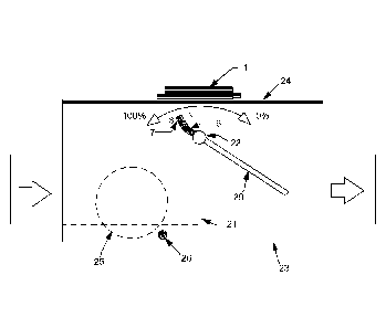
an
installed sewer back-flow preventer valve comes with some challenges. The
first
challenge was the need for the periodical cleaning of the valve to ensure
proper
functioning of the valve. If the valve were to become filled with debris, the
valve
could fail to close properly and fully during an event of a municipal sewer
back-flow,
allowing flooding which the valve was supposed to prevent.
4. The question arose, how would one know if the valve was becoming
impaired
with dirt and in need of cleaning. A regular regimen of cleaning would prove
useful
but will not compensate for variance in usage. Also, neglect is a consequence
of a
busy lifestyle.
5. The second concern was in regard to the valve operating properly during
an
event of municipal sewer back-flow. If an event were to occur that resulted in
the
sewer back-flow valve successfully closing, then municipal sewer contents
would be
prevented from flooding the basement. However, a closed sewer back-flow
preventer valve would also prevent the egress of wastewater generated by the
occupants within the dwelling. This would result in secondary flooding, as
wastewater would back up into the basement through the floor drain or a
downstairs
shower drain or even a toilet.
Page 1
Date Recue/Date Received 2021-06-21
6. The contractor was queried on these issues but was unable to offer an
alarm for
the closure of the valve, nor had they any idea concerning a device that could
warn
the homeowner of a dirt impaired valve.
7. An internet search was started for a device that could be attached to
the sewer
back-flow preventer valve to offer some sort of warning. Feedback from the
contractor indicated that other homeowners who also had a valve installed were
concerned with these issues as well. Some individuals had gone as far as home
fashioned devices that could warn of a closed valve.
8. As I was unable to locate a device that provided a comprehensive
solution, I set
about to design my own. It was a challenge because I did not want to do
anything to
the back-flow preventer valve, -which was supplied by the contractor in
advance-
such that they would refuse to install it. I also did not want to do anything
to the
valve that might cause the plumbing inspector to disapprove of the
installation of the
sewer back-flow preventer. Thus, the design was made as unobtrusive as
possible
and constructed to be obviously harmless to the main purpose of the sewer back-
flow preventer valve. The installation was successful. The plumbers felt the
attached
device was satisfactory and the installation also passed city inspection.
9. The prototype installed at my principle residence was designed and
constructed
within a narrow timeframe due to constraints placed upon us by the insurance
company and the contractor. However, it was my intention to build a device
that
could also be installed upon a preexisting valve in order to satisfy strong
retail
demand for such a device. The prototype used the simplest methods of
construction
in order to fit our allotted time. The final designs could either be part of
the
backwater valve when manufactured by the backwater valve OEM or be an 'off the
shelf', installed by homeowners with some technical ability.
10. In my initial search for a device that would offer some type of alert,
I found one
device online that offered some protection. It was sold by an online
distributor at
http://www.backwater-valves.com/flood-alarm.asp. This device works by sensing
continuity between two electrical probes and I considered this device, however
it has
its drawbacks. The metal probes will corrode and/or be coated with residue and
is
hence unreliable. It does not inform residents as to whether a backwater valve
has
Page 2
Date Recue/Date Received 2021-06-21
actually closed, but merely alarms if municipal sewer water is backing up, if
it is in
fact in working order at all. Neither does it offer any alert as to the
buildup of debris
in the valve. I searched for an associated patent for this device and found
"Sewer
alarm apparatus having a probe", patent US10,032,357, application
US15/137,599.
This design focuses on "detecting the presence of liquid within a pipe" Cite
7, and
may not be associated with the device at the website mentioned, although its
function appears identical. This idea does not achieve the needed result and
is
subject to corrosion and failure.
11. Once my search for a patented device began, I decided to file a
provisional
patent application US 62/761,423 for my Sewer Back-flow Preventer Monitor. I
continued my search for devices and found "Sewer alarm" patent US 4,922,234,
application US 07/275,371. This device contains a "buoyant mercury switch
tethered" Cite 4, to sense high water level. As an electrician working in the
manufacturing industry for almost 40 years, I know this to be a poor
application.
Sewage is constantly moving through this valve. This switch will fail quickly
and also
it can impair the function of the valve. It will get coated with sewage and
block the
flow. Also, it offers no alert of the valve's sediment buildup.
12. Another patent I observed is "Sewer backup alarm" Patent US 9,123,230,
application US 13/894,153. This alarm "includes a float device and a wireless
alert
device" Cite 5. Again, experience shows that this float switch will become
coated
with sewage and fail. Also, it offers no alert for debris buildup in the
valve.
13. I looked at "Sewer line backup detection, alarm and detention apparatus
" Patent
US 4,546,346, application US 06/475,688. This device, a "pneumatic switch is
actuated by a flexible diaphragm" Cite 3. is also poor construct. These
switches are
notorious for failure, more so in this environment. This switch will get
plugged up in
short order and the diaphragm will decay. The final patent I discovered which
bore
similarities to what I intended to build is covered under pending application
U515/720,925 and is an "apparatus for detecting an impending sewer backup by
detecting fluid undulations of predetermined magnitude" Cite 1, the focus of
this
device is predictive. This device is a non-starter, as it is designed for a
valve which
municipalities have been steering away from. The reason being the flapper of
this
Page 3
Date Recue/Date Received 2021-06-21
valve rests on the bottom of the valve housing and will glue to the bottom in
the
sediment, hence it will not close and a flood ensues. This design uses a "tilt
switch
carried by the gate" Cite 2, which can only demonstrate a single position of
the
flapper, and as such, cannot offer a user an alarm when the valve needs
cleaning.
Nor can it offer an alarm if the switch is being used for 'predictive
purposes', as
outlined in the application. This wireless switch would be positioned on the
inside of
the valve, in the sediment. It is not practical, as the battery will have to
be replaced
and there will not be the will to dismantle the valve, clean the switch from
the nasty
stuff, and change the battery. This application also postulates the possible
use of "a
sensor for sensing fluid undulations of predetermined magnitude" Cite 8,
without
detailing what type of sensor it is. However, based on the requirements
described, it
would be a costly sensor, multiples of the price of the valve itself. It is
therefore not
cost effective.
14. I searched for a patent that utilized reed switches or a magnetometer
and a
magnet to indicate valve position. I found only "Valve position indicator"
Cite 6,
US3896280A, an apparently expired patent. My prototype utilizes a similar
device as
this, but within the context of a sewer backwater valve instead of an
automotive
valve, much in the same way the aforementioned patents utilized existing
hardware
within the context of their patents. For example, a pressure switch or a float
switch,
or a continuity switch, all devices that have previously been patented.
BRIEF SUMMARY OF THE INVENTION
15. The Sewer Back-flow Preventer Monitor is an electrical monitoring
device to be
added to a sewer back-flow prevention valve. It consists of a sensor, a magnet
and
a connected indicating circuit within the Controller. The indicating circuit
has
provision to connect to home alarm systems and to internet enabled devices.
The
Controller itself could also be fitted with a wireless module to connect to
home WiFi
and r&d is ongoing for the best working system. The Sewer Back-flow Preventer
Page 4
Date Recue/Date Received 2021-06-21
Monitor performs two important tasks. Firstly, it alarms homeowners when their
installed sewer back-flow valve is fully closed, or partially such, during an
event of
municipal sewer back-flow. Secondly, it will alert homeowners to the need for
cleaning of the sewer back-flow preventer valve. It can perform both functions
even
while users are away, where internet connected devices, made by others, are
utilized, or where the Controller is fitted with a WiFi module.
16. During a municipal sewer back-flow event causing the backwater valve to
be
closed, an alarm will warn the occupants of a dwelling in order that they not
to use
plumbing fixtures within the dwelling to prevent secondary flooding.
17. Sewer back-flow preventer valves should be routinely cleaned of residue
that
builds up in the bottom of the valve. In this instance the Sewer Back-flow
Preventer
Monitor would cause an alert to be generated, informing the occupants that the
back-flow preventer valve was in need of attention.
18. Other systems which are designed to alarm in the case of a municipal
sewer
backup event do not offer the same protections that the Sewer Back-flow
Preventer
Monitor does. The other systems do not indicate that one's backwater valve is
actually closed during an event of backup, rather they only hope to alarm
persons
when there is water in the valve, something that, in the case of a failed
valve, they
would already be aware of because of the copious amounts of water in their
basement. Neither do they offer any alert concerning the buildup of unwanted
material inside the backwater valve which could impair its operation.
19. Other systems do not offer the robust performance of the Sewer Back-
flow
Preventer Monitor which is designed to be unaffected by the disagreeable
environment within the valve. Other systems use methods of detection that are
inadequate and have over time proven to fail. These other systems do not last,
they
get plugged up and decay. Other than a known system that uses continuity to
sense
high water, none of these other systems are available for purchase at retail,
most
likely for reasons discussed here.
20. The object of the Sewer Back-flow Preventer Monitor is to keep
homeowners
appraised of the health of their installed sewer back-flow preventer valve and
to alert
them when attention is needed, whether that be the valve's need for cleaning
or its
Page 5
Date Recue/Date Received 2021-06-21
status during a sewer backup event. It offers the peace of mind that only a
Sewer
Back-flow Preventer Monitor can, by making homeowners aware that their valve
has
successfully and completely shut, preventing a flood. When the Sewer Back-flow
Preventer Monitor is connected to the internet using a variety of interfaces,
it offers a
homeowner, even when away from home, an alert that gives confidence and
creates
calm during a municipal sewer backup event.
BRIEF DESCRIPTION OF THE SEVERAL VIEWS OF THE DRAWINGS
21. FIG. 1 is a general layout showing how the full working system would be
assembled. The Sewer Back-flow Preventer Monitor sensor, to be mounted on the
valve housing lid 24, the connected wiring to the controller 2,27, the
controller 3 with
its associated wiring 2,4,5,27 and the magnet arm 6 containing a neodymium
magnet 7.
22. FIG. 2 and FIG. 3 is the sensor 1. A front view Fig. 1 with internal
contents shown
and a side view Fig. 2.
23. FIG. 4 shows the controller 3. The indicator LED's array 14 , the Horn
19 and the
pushbutton switches array 15 for silencing the alarm and setting up the throw
on the
valve are dark shaded to demonstrate the exterior. On the interior is seen the
battery
18 and the micro controller 17 and output relays array 16.
24. FIG. 5 shows the valve with the installed prototype on the side of the
valve
opposite the ball float 25. It was used as proof of concept and continues to
provide
our home safety. It utilizes reed switches 28 and a side mounted switch
assembly
13. Although working well, this is not advised for retrofit applications, as
this area of
the valve is mostly inaccessible after valve installation.
25. FIG. 6 again shows the sewer back-flow preventer valve 23 from the side
opposite the ball float, with the Sewer Back-flow Preventer Monitor sensor 1
mounted on the lid 24 and the offset magnet arm 7 mounted on the flapper hinge
6.
Seen here is the ball float 25 at the other side and indicated by sediment
accumulation 26 is the area under the ball float where sediment will
accumulate.
Page 6
Date Recue/Date Received 2021-06-21
26. The Sewer Back-flow Preventer Monitor works by live reporting of the
position of
the flapper in an installed sewer back-flow preventer valve, and then issuing
an alert
or alarm based on that position. Hereafter, the sewer back-flow preventer, or
backwater valve will be abbreviated to "valve", and the Sewer Back-flow
Preventer
Monitor will be abbreviated to the acronym SBPM. The valve that is referred to
herein is model ML-FR4 from OS&B Mainline products. It is covered by USA
patent
4503881 as disclosed in PTO/SB/08a and found at https://www.backwater-
valves.com/ML-FR4-Mainline%20Backwater-Valve-Fio-Valve.asp. Their drawings
are not included within this specification. The municipality in which the
prototype,
described herein, is installed ceased to allow, to be installed, the older
style back-
flow preventer manufactured by the same company. The reason is, it had proven
to
fail in the open position causing a flood, specifically, their back-flow
preventer valve
with the flapper on the bottom. This is the same failed valve mentioned in the
Background section, with reference to USA patent application US15/720,925.
27. The position of the valve flapper 29 changes with regard to real world
conditions.
There are four positions that are of importance. Firstly, during normal use
operation
of the valve with 100 percent throughput of wastewater, the valve flapper
should be
fully open and the SBPM will indicate normal function of the valve.
28. Secondly, when the valve has built up a level of debris 26 (Fig. 6),
causing the
valve flapper to be less than fully open, approximately at 90% open, the SBPM
will
indicate a need for cleaning.
29. Thirdly, during a municipal sewer back-flow of wastewater, the valve
flapper may
not fully close due to debris which could lodge between the valve flapper 29
and its
seat 21. The SBPM sensor will indicate that the valve is more than fifty
percent
closed but not fully closed and the controller will issue a strong alert
indicating that
the valve has failed and almost certain flooding conditions exist.
30. Fourthly, during a municipal sewer backup or back-flow of wastewater,
the valve
flapper is fully closed when successful, preventing back-flow and flooding.
This
would be zero percent open. An alarm is issued warning occupants against the
use
Page 7
Date Recue/Date Received 2021-06-21
of plumbing fixtures within the dwelling, or other building where they valve
is
installed, so that secondary flooding is prevented.
31. Connections 5,16,27 are available on the SBPM controller to allow for
the use of
internet connected devices made by others, such that in the event of a
municipal
sewer back-flow, persons could be informed that they have been spared a flood.
32. The SBPM is comprised of a sensor 1, a magnet 7 with attaching arm 6
and a
controller 3 with associated wiring. (FIG. 1)
33. The position sensor 1, (FIG. 1,2,3,5) is comprised of a watertight
enclosure 13
containing a circuit board 10, the circuitboard bearing a minimum of three
Hall-effect
transistors 11, (FIG. 2) shown, or four reed switches 28 if factory installed
(FIG. 5).
When reed switches are used, more precise placement of the sensor module is
required, and also a more precise installation of the magnet arm 6. The
function of
the reed switch sensor can only be adjusted mechanically, by repositioning.
Hence,
reed switches are not shown as it has been determined that their use does not
facilitate the "best mode contemplated" when a retail use is the focus.
34. The prototype (Fig. 5) utilizes four reed switches 28 and demonstrates
well the
value of this invention, however, this was a meticulous installation by
myself. The
prototype does not utilize a controller 20 as does the Hall-effect transistor
11 design
(FIG. 2, Fig. 5) described within this specification. The prototype is
directly
connected to a security alarm system and offers its full function through the
security
alarm interface keypads. The prototype illustrates well how a good result
could be
achieved if a manufacturer of backwater valves chose to implement this idea
during
the manufacture of their valve, as an improvement. However, the invention
described within (Fig. 1,6) utilizes Hall-effect transistors 11 and a micro
controller 17
as this method can find better success as a user installable device.
35. The sensor 1, using three Hall-effect transistors 11 is seen in FIG. 2.
The
transistors are mounted on a circuit board 10, one on each end over its length
and
the third in the middle. They are supplied their working voltage by means of
connected cable 2, also as seen in FIG. 1, that issues from the controller
module
and the transistor's output is fed back the the controller module. The sensor
housing
13 is made of plastic and is sealed during manufacture. The sensor is four
inches
Page 8
Date Recue/Date Received 2021-06-21
long and three-quarters of an inch wide. Taking into account that this device
is an
add-on to an existing product, these dimensions could vary, depending on the
target
valve, as no two valve manufacturers are identical. This design, however, was
intended to become universal. The sensor 1 is to be mounted on the cover 24 of
the
valve housing, over top of the flapper hinge 22 and on the side opposite the
float ball
as seen in FIG. 6. It will receive magnetic force from the moving magnet 7
below it
through the magnet's arc of travel and will generate a signal to be processed
by the
micro controller 17 in the controller enclosure.
36. The magnet arm 6 containing the magnet 7 is to be mounted directly on
the
flapper hinge 22, inside the valve housing 23. (FIG. 1, FIG. 6). It is made of
plastic
and the magnet is integral. The arm is offset according to the manufacture of
the
particular valve it is to be installed upon, such that the arc of travel is
uniform from
open to closed positions of the flapper. In the case of the valve that was
used for
proof of concept, the arm is slid onto the flapper hinge so that the hinge
rests inside
the mounting slot, with the arm facing upwards. This is done on the side
opposite
the ball float 25. A hole is drilled through the fastening hole 8, (FIG. 1),
and through
the flapper hinge. A stainless steel screw with a nut are used to secure the
arm. The
offset allows the magnet to travel in an arc just below the lid of the valve,
underneath the Sensor.
37. With the magnet arm fastened to the flapper hinge, the magnet will
travel in an
arc, in the opposite direction of the flapper. (FIG. 6). When the flapper is
fully open,
the magnet is toward the inlet end of the valve at 100%. As the float ball
rises with
the water level, the flapper begins to close and the magnet travels forward,
toward
the outlet end of the valve. When the flapper is fully closed, the magnet is
at the end
of its travel toward the outlet end of the valve at 0%.
38. The correct sensor position is discovered by placing it on top of the
valve cover,
directly over the installed magnet arm and with the controller connected and
energized and the valve fully open. The controller indicator for position 1
will
illuminate when the valve is in position. The valve flapper must be physically
operated to its closed position in order to establish the proper setting on
the
controller. To operate the valve flapper manually on the valve used for this
Page 9
Date Recue/Date Received 2021-06-21
specification, a small hole must be drilled in the cover, through which a
narrow rod
can be inserted to push the flapper shut. This hole will be sealed with a
removable
plug until it is time to test the system, most probably at the time of valve
cleaning.
39. The controller can remain with the valve in the valve pit, however it
will be more
difficult to hear the alarms and alerts in this position. It is preferable
that the
controller be outside of the valve pit and mounted on the near outside wall
where the
valve is installed. For this to be the case, a corridor for the connecting
cable A must
be established. This is accomplished without difficulty during valve
installation,
however this would otherwise require cutting a concrete floor. In cases where
it is
not possible to have the controller mounted outside of the valve pit, it may
remain in
the pit, underneath the pit's cover. It is prudent to connect the controller,
using the
relay outputs, to a security alarm system, directly or wirelessly. Or, to an
internet
enabled device capable of issuing a text or email. Future iterations of the
Controller
will offer direct WiFi connectivity.
40. The SBPM Controller uses a programmable micro controller integrated
circuit,
selecting from one of many cost effective micro controllers readily available
and the
micro controller will be programmed according to the programmer's style. It is
programmed using the table below.
41. Programming Table 1
Status Pos. Li L2 L3 L4 Al A2 ALM RI R2 R3
Open >97% On Off Off Off Off Off Off Off Off Off
Need cleaning 96-80% Off On Off Off On Off Off On Off Off
Valve failure 79-4% Off Off On On Off Off On Off On On
Valve closed >3% Off Off Off On Off Off On Off On Off
Low Battery NA Flash Off Off Off Off On Off Off Off
Off
42. See FIG. 4, where L1-L4 14 indicate valve position and battery.
43. Al is a minor Alert that indicates a need for cleaning. It may be
temporarily
silenced by depressing both pushbutton switches on the controller. A2 is minor
alert
to battery condition. R1, R2 and R3 16 are relay outputs to provide
connectivity to
Page 10
Date Recue/Date Received 2021-06-21
home security systems and other internet connected devices by others. They
relate
to the alerts and alarm as seen in the above Programming Table. The
nomenclature
marked on the Controller face would indicate the action to be taken.
44. The micro controller is able to be updated from time to time if
necessary, as more
data is retrieved from the field, such that nuisance alerts can be eliminated.
45. The Hall-effect transistors 11 mounted within the Sensor 1 (FIG. 2)
will output a
small voltage, and the position of the moving magnet mounted on the flapper
hinge
beneath it (FIG. 6) will cause the voltage from the three transistors to rise
and fall
and change polarity. These voltages are input to the micro controller 17 (FIG.
4)
analog inputs and the programmed micro controller extrapolates the valve
position.
Digital outputs on the micro controller energize the relays 16.
46. Seen in FIG. 1, the outputs from the relays are available by means of
Cable 5.
Cable 4 is for supply voltage from a remote power source.
47. The alert for valve cleaning is determined by the valve position, that
being less
than fully open, see Table 1, and this condition persisting for longer than
the set time
of 1 hour. This is to eliminate nuisance alerts from flapper movements during
normal
usage. Thus, a user would be alerted to a buildup of debris in the bottom of
the
valve.
48. The alarm for valve failure and the alarm for successful valve closure
during an
event of backup or back-flow would be instantaneous. All alarms and alerts can
be
cancelled with the use of the push button controls when inspecting the
situation.
Page 11
Date Recue/Date Received 2021-06-21