Note : Les descriptions sont présentées dans la langue officielle dans laquelle elles ont été soumises.
CA 03066868 2019-12-10
WO 2018/235039 1 PCT/IB2018/054602
A LIGHT FRAME
FIELD OF THE INVENTION
[0001] The present invention relates to a light frame, particularly an
edge-lit light
frame, suitable for receiving sheet graphics/artwork for display.
BACKGROUND OF THE INVENTION
[0002] Light frames, also known as light boxes, are common as an advertising
display means in retail and service industries. A light frame is typically
formed as a
sandwich of components, e.g. an outer frame or housing, a transparent front
panel,
printed graphics material or content, a light source/diffusion and a rear
panel. It is also
now common to implement a light guide panel (LGP) associated with the light
source,
intended to optimise the uniformity of light distribution so that the back
lighting on the
printed material is even, resulting in an attractive and bright front view.
[0003] Available LGPs are formed from poly(methylmethacrylate) resin, i.e.
PMMA
or acrylic, also known by trade names such as PlexiglassTM and PerspexTM, as a
flat
surface upon which a dot/line matrix is either printed or etched. The panel is
coupled to a
light source at its edge, usually in the form of LEDs or a florescent lamp.
The effect of the
surface matrix is to reorient the edge-lit source to transmit across the front
and rear
surfaces. Reorientation of the light can be achieved for example by an
internal reflection
of the received light.
[0004] Artwork is typically printed on a translucent polyester film or
equivalent
which provides a vivid image in daylight, yet also can be illuminated from
behind when
the light source is activated.
[0005] Double-sided light frames/boxes are known which feature a LGP located
centrally, with printed artwork mounted either side thereof, pressed against
and visible
through front and rear transparent panels. Double-sided light boxes can
feature a single
LGP or two LGPs back-to-back.
[0006] Various light box designs are available, ranging from movie theatre
wall
mounted advertising to shop window product displays. A particularly popular
application
is to feature a series of light frame displays in the window of a real estate
agent where
property photographs and information are displayed to catch the eye of
potential buyers.
It is usual to mount such displays in a hanging or cluster arrangement close
to the
windows glass so the display is easily visible from outside. However, a
problem
encountered with available light boxes is that, when positioned close to a
window, access
to change the printed material on the window side of the frame is difficult.
This is often
exacerbated by the presence of support/power cables and the close proximity of
adjacent
light boxes. In some cases, the lightbox display needs to be dismantled in
order to
change the printed material.
CA 03066868 2019-12-10
WO 2018/235039 2 PCT/IB2018/054602
[0007] The requirement to regularly dismantle and reconfigure light frames,
e.g.
in a window display, is inconvenient and time consuming for the business.
SUMMARY OF THE INVENTION
[0001] It is an object of the invention to provide a light frame which
addresses
and overcomes or at least ameliorates some of the above mentioned
disadvantages or
which at least goes some way toward providing for a useful alternative.
[0002] In a broad aspect the present invention provides a light frame
comprised
of a transparent front panel, a rear panel and an edge-lit light guide panel
between the
front panel and rear panel, for illuminating content located at least between
the front
panel and the light guide panel, wherein the rear panel, and optionally the
front panel,
are openable to provide access to the light guide panel, and wherein the light
guide panel
is displaceable from the front panel in situ.
[0003] In a preferred form the light guide panel is hinged at an edge so as to
be
openable for providing access to a void in the frame where content (e.g. a
sheet of
artwork) is mounted for display. Such a hinge may be directly attached to the
LGP or to a
separate housing/frame around the LGP. In an alternative form the light guide
panel is
detachable by virtue of magnets, e.g. a magnetic strip located along an edge
thereof, for
coupling with an opposite polarity magnetic strip associated with a frame
housing.
[0004] In one form the light frame includes a frame providing a peripheral
border
and holding the front, rear and light guide panels in place. However, an
alternative form
may integrate the frame into the front and/or rear panels, e.g. panels include
mating
flanges that form an enclosure for the light guide panel and associated
electrical
components therewithin.
[0005] In a preferred form the rear panel is additionally transparent so as to
provide a double-sided display device. In the case of a double-sided display,
the front
panel may be fixed (e.g. to a frame), but the rear panel is removable or
openable,
providing access to the displaceable light guide panel within. The rear panel
may be
hinged to a frame or front panel; alternatively, it may be removable by some
other
means such as magnets or screw fasteners.
[0006] The advantage of such an arrangement is that, while the light frame is
in
place for display, e.g. mounted/hanging in a shop window, the user can gain
access from
the rear side to content adjacent the rear panel and, at the same time, the
displaceable
light guide panel will enable access through the frame (light box) to the
content adjacent
the front panel. In this way, displayed content can be removed and substituted
on both
sides of the light box while only one side of the light box has been opened
for access. In
practice, this enables a light frame to have its front face positioned closely
against a
window/permanent glass structure while preserving the ability to
replace/update printed
material/content easily and without the need to completely demount and
disassemble the
CA 03066868 2019-12-10
WO 2018/235039 3 PCT/IB2018/054602
light frame. The invention improves utility and overcomes the difficulty of
changing
graphics experienced with known light frame designs.
[0007] In a preferred form, the frame includes a means of hanging extending
therefrom for suspending the front panel in a displayable position, e.g.
cables either side
of the light frame with connectors extending from the frame to the cables.
Alternatively,
the cables may include a threaded connector for coupling with the front panel
or frame,
or the front panel/frame may feature a channel therethrough to accommodate the
cable,
secured in place by an interference fit or a fastener capturing the cable in
the channel.
[0008] In another aspect, there is provided a light frame comprising:
a transparent front panel;
a mounting means for locating the front panel in a displayable position;
a rear panel;
a light emitting means; and
at least one light guide panel disposed between the front panel and rear panel
and
configured to receive light at an edge thereof from the light emitting means
for, in
use, illuminating content disposed between the front panel and the at least
one
light guide panel;
wherein, in use, the rear panel is displaceable to provide access to the at
least
one light guide panel; and
wherein the at least one light guide panel is displaceable from the front
panel
and/or mounting means while the front panel is located by the mounting means
in
a displayable position to, in use, provide access to content disposed between
the
front panel and the at least one light guide panel.
[0009] In a preferred form, the rear panel is transparent such that, in use,
content
disposed between the rear panel and the at least one light guide panel may be
illuminated.
[00010] In a preferred form, the mounting means includes a frame supporting
the
front panel.
[00011] In a preferred form, the front panel is fixed to the frame.
[00012] In a preferred form, the at least one light guide panel is
displaceable by
virtue of a hinged edge attached to the front panel or mounting means.
[00013] In a preferred form, the hinged edge is different to the edge
receiving light
from the light emitting means.
[00014] In a preferred form, the hinged edge comprises one or more hinge
portions.
[00015] In a preferred form, the one or more hinge portions comprise a slot
for
receiving the at least one light guide panel.
CA 03066868 2019-12-10
WO 2018/235039 4 PCT/IB2018/054602
[00016] In a preferred form, the hinged edge comprises two hinge portions
disposed in line, and configured to operate together to provide a hinging axis
for
the at least one light guide panel.
[00017] In a preferred form, the at least one light guide panel is
displaceable by
virtue of at least one detachable connection disposed at an edge of the at
least
one light guide panel relative to the front panel or mounting means.
[00018] In a preferred form, the at least one detachable connection is one or
more
of the following, alone or in combination: a clip, a magnet, an interference
fit, an
adhesive strip, a hook and loop pad or functional equivalent.
[00019] In a preferred form, there are one or more detachable corner pieces.
[00020] In a preferred form, the one or more corner pieces comprise a recess
for
receiving the at least one light guide panel.
[00021] In a preferred form, the one or more corner pieces further comprise at
least one stepped region or at least one region of greater internal width for
receiving printed material.
[00022] In a preferred form, the rear panel is displaceable relative to the
front
panel by virtue of a hinged edge attached to the front panel or mounting
means.
[00023] In a preferred form, the rear panel is displaceable relative to the
front
panel by virtue of at least one detachable connection.
[00024] In a preferred form, the at least one detachable connection is one or
more
of the following, alone or in combination: a threaded fastener, a clip, a
magnet,
an interference fit, an adhesive strip, a hook and loop pad or functional
equivalent.
[00025] In a preferred form, the mounting means includes a hanging means.
[00026] In a preferred form, the hanging means comprises at least one cable
for
suspending the front panel in the displayable position.
[00027] In a preferred form, the cable includes a threaded connector for
coupling
with the front panel or mounting means.
[00028] In a preferred form, the mounting means includes a channel to
accommodate the cable.
[00029] In a preferred form, there may be a fastener to secure the cable in
the
channel.
[00030] In a preferred form, the at least one light guide panel comprises a
modified
surface configured to reorient the received light (e.g. such as by internal
reflection) to content disposed on the light guide panel.
[00031] In a preferred form, the modified surface comprises an etched surface
matrix on one or both sides of the light guide panel.
[00032] In a preferred form, the modified surface comprises a printed surface
matrix disposed on one or both sides of the light guide panel.
CA 03066868 2019-12-10
WO 2018/235039 5 PCT/IB2018/054602
[00033] In a preferred form, the at least one light guide panel comprises two
or
more panels formed as a light guide panel assembly.
[00034] In a preferred form, the light guide panel assembly comprises at least
one
modified surface configured to reorient the received light to content disposed
on
the light guide panel assembly.
[00035] In a preferred form, the modified surface comprises an etched surface
matrix on at least one side of at least one panel comprising the light guide
panel
assembly.
[00036] In a preferred form, the modified surface comprises a printed surface
matrix disposed on at least one side of at least one panel comprising the
light
guide panel assembly.
[00037] In a preferred form, the modified surface is disposed between the two
or
more light guide panels forming the assembly as a sandwich configuration.
[00038] In a preferred form, the two or more light guide panels formed as an
assembly are supported together by the one or more hinge portions and/or
corner
pieces.
[00039] In a preferred form, the at least one light guide panel comprises at
least
one substantially planar surface for receiving content.
[00040] In another aspect, there is provided a poster or content sheet
supported
by the light frame as described by either of the aspects or preferred forms
above.
[00041] In the context of the invention 'displaceable' and 'openable' are
interchangeable concepts and refer to the capacity to give access.
Furthermore, the
term 'comprising' as used in this specification means 'consisting at least in
part of'.
When interpreting statements in this specification which include that term,
the features,
prefaced by that term in each statement, all need to be present but other
features can
also be present. Related terms such as 'comprise' and 'comprised' are to be
interpreted
in the same manner.
[00042] The term 'front' generally refers to the primary display side of the
light
frame, e.g. that side facing a window or best positioned for a viewing person.
The term
'rear' is generally the opposite side to the front and, in the case where the
frame is
closely mounted against a window, the side which is furthest from the window
glass.
'Front' and 'rear' give the invention context but could be interchangeable
with 'first' and
'second'.
BRIEF DESCRIPTION OF THE DRAWINGS
[00043] The invention will now be described by way of example only and with
reference to the drawings in which:
[00044] Figure 1 illustrates a general view of a light frame according to the
invention, in an open configuration;
CA 03066868 2019-12-10
WO 2018/235039 6 PCT/IB2018/054602
[00045] Figure 2 illustrates a rear elevation view of an assembled or closed
light
frame from Figure 1 and a first embodiment of cable suspension system relative
to light
frame according to the invention; and
[00046] Figure 3 illustrates a second embodiment of cable suspension system
capable of being implemented with the invention; and
[00047] Figure 4 illustrates a third embodiment of cable suspension system
capable
of being implemented with the invention.
[00048] Figure 5 illustrates a general view of the front of a light frame
according to
the invention.
[00049] Figure 6 illustrates a general view of the rear of a light frame
according to
the invention.
[00050] Figure 7 illustrates a first embodiment of a hinge capable of being
implemented with the invention.
[00051] Figure 8 illustrates a first view of a hinge capable of being
implemented
with the invention.
[00052] Figure 9 illustrates a second view of a hinge capable of being
implemented
with the invention.
[00053] Figures 10A, 10B, and 10C illustrate first embodiments of a light
guide
panel capable of being implemented with the invention.
[00054] Figures 11A, 11B, 11C, and 11D illustrate second embodiments of a
light
guide panel capable of being implemented with the invention.
DETAILED DESCRIPTION
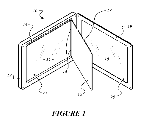
[00055] Figure 1 shows a general view of a preferred embodiment of the present
invention. A light box or frame 10 is primarily comprised of a front panel 11
that is
bordered by and attached (i.e. either permanently or removably fixed) to a
supporting
frame 12 which, in turn, is mountable in an appropriate location, e.g. in a
shop window.
The illustrated form of the frame utilises a cable suspension system 13 which
is shown in
further detail by Figures 2, 3 and 4.
[00056] In order to perform as a light frame, a light emitting means is
provided at
one or more edges of the frame 12 which, in the illustrated form, is an LED
strip 14
located across an upper edge.
[00057] The distribution of light from the LED strip 14, suitable to provide
back
lighting to content placed against front panel 11, is improved by a light
guide panel 15 of
a general type known in the art. According to the present invention, LGP 15 is
displaceable in situ from the front panel 11 which, in the preferred form
illustrated, is
embodied by hinges 16 at one edge so that the LGP can swing away from the
front panel
11. By virtue of hinges 16, LGP 15 can generally remain attached to the total
structure
of frame 12 to improve convenience when replacing artwork content located
against front
CA 03066868 2019-12-10
WO 2018/235039 7 PCT/IB2018/054602
panel 11. Preferably the LGP 15 is hinged to frame 12 at an edge different
from the
location of LED strip 14, leaving an exposed edge 17 free to align with LED
strip 14 when
the LGP is in a closed position. To be effective the alignment between the LGP
and LED
strip's respective edges do not have to be exact but preferably the hinge
arrangement
will move LGP 15 into position with relatively close accuracy. LGP 15 may be
hinged
directly to frame 12 / front panel 11 as illustrated or be mounted in a
separate frame
that, in turn, is attached by a hinged edge to the frame/panel.
[00058] In the illustrated form LED strip 14 is installed within the upper
edge of
frame 12, however, alternative embodiments may elect to install an LED strip
14 directly
to LGP 15 or a separate surrounding frame. The preference for which system to
use will
be apparent to a skilled person in context.
[00059] Light frame 10 further includes a rear panel 18, optionally surrounded
by a
frame 19. In use, rear panel 18 can be transparent and provide a second
viewing face for
content placed against the rear side of the LGP 15 since it transmits light in
both outward
directions from its main front/rear surfaces. Accordingly, the illustrated
form of the
invention is a double-sided light frame.
[00060] Like LGP 15, rear panel 18 is openable relative to the front panel 11,
either
by virtue of a hinge arrangement suggested (although not visible) by Figure 1
or,
alternatively, entirely separable where the rear panel 18/19 is removed by
virtue of
screw fixings, magnets or other suitable fasteners.
[00061] An openable rear panel firstly allows access to a rear portion 20
behind
panel 18 within which display content can be mounted (e.g. by sandwiching said
content
between the inner face of panel 18 and a face of LGP 15) and visible from the
rear side of
the light frame. Secondly, opening the rear panel gives a user access to LGP
15 that is
itself opened via hinges 16 or otherwise removable in order to provide access
to a front
portion 21 behind front panel 11 where display material is mounted (e.g.
sandwiched
between an inner face of panel 11 and a face of LGP 15). All the while, frame
12 and
front panel 11 remains in place, e.g. by the cable suspension system 13, and a
user is,
therefore, able to gain access to both front and rear portions 20 and 21 to
easily remove
and replace/update content from both sides of the light frame 10 without
complete
disassembly being necessary. The gaps/spaces of portions 20/21 for mounting
content
may be very thin, for receiving and sandwiching sheet material, or have a
depth to
receive thicker items. Further mounting options can be provided for holding
display
content against front and rear panels respectively dependent on the nature of
material.
[00062] The embodiment of Figure 1 keeps all components connected together by
virtue of hinge arrangements for LGP 15 and rear panel/frame 18/19, although
it will be
apparent that alternative solutions could be employed to achieve an
approximately
equivalent result. For example, magnetic strips may be provided around edges
of either
the LGP 15 or rear frame 19 or both to enable temporary removal of these
components
CA 03066868 2019-12-10
WO 2018/235039 8 PCT/IB2018/054602
from magnetic strips or a metal portion upon corresponding edges/locations on
front
panel 11 or frame 12.
[00063] Figures 2, 3 and 4 illustrate alternative examples of a cable
suspension
system 13. For example, Figure 2 shows a solution where suspension wires 23
are
located either side of the light frame with pairs of connector mounts 27
situated on each
side of the frame and connected to the wires 23 using a suitable
fastener/clamp
arrangement 26. Connectors 27 could be fitted to either the long or short
sides of the
light frame, which would enable the frame to be displayed in both landscape
(pictured)
and portrait formats.
[00064] Figure 3 shows a solution where a screw/bolt fitting end 22 of a
cable/wire
23 is insertable into a threaded socket 24 associated with a side of frame 12.
Preferably
the end 22 is freely rotatable relative to wire 23 so it does not twist the
wire during
threading of the screw end. At least two, but preferably eight, such socket
arrangements
24 would be needed to suspend light frame 10, two on each side of frame 12
and,
furthermore, opposite ends of a suspension cable 23 can include a screw
fitting 22 to
enable multiple light frames 10 to be arranged in line in a vertical
arrangement. Screw
fittings 24 located on both the long and short sides of the light frame 10
would enable
the light frame 10 to be displayed in both landscape and portrait formats.
Outermost
suspension wires 23 with fitting ends 22 extending from a light frame 10 will
be attached
to a wall, ceiling, floor, window-frame or the like mounting position to
suspend the total
arrangement of one or multiple light frames.
[00065] Mains power electrical connections for the LED strip 14 and associated
electronics (not shown) can be built into the cable suspension system 13 to
power it in a
discrete manner. Alternatively, the light source could be battery operated and
require
periodic recharging.
[00066] Figure 4 illustrates an alternative embodiment, shown in an open
configuration where rear panel 18 is hinged to front panel 11 by the
respective frames
12, 19. A suspension wire 23 is threaded or lead into a channel 25 extending
all the way
through an edge portion of front frame 12. An interference fit or suitable
fastener/clamp
arrangement 26 can be utilised to hold wire 23 in place so that light frame
will be
suspended in place.
[00067] As with the above example of Figure 3, multiple light frames 10 could
be
arranged in line in a vertical arrangement. Likewise, electrical connections
can be
incorporated into the suspension system to provide discrete power to the LED
strip 14
and associated electronics. Additional channels 25 and interference
fits/fasteners/clamps
26 located perpendicular to those illustrated would enable the light frame to
be displayed
in both landscape (pictured) and portrait formats.
[00068] Figure 5 illustrates a front view of an embodiment of the present
invention
with the front panel removed. In this embodiment, frame 12 is shown with
optional
CA 03066868 2019-12-10
WO 2018/235039 9 PCT/IB2018/054602
hollow sections and cross struts 29 to strengthen the frame 12. The cross
struts 29 also
provide a surface area to attach the front panel, for example using adhesive
tape.
[00069] LED strips 14 are shown on both long edges of frame 12, and are
connected to electrical contacts 30 capable of external connection to a power
source. It
will be apparent that LED strips 14 could also be disposed on one or both
short edges of
the frame 12, or in any other appropriate location for distribution of light
to provide side
and/or back lighting to the LGP 15. As outlined above, it will be apparent
that LED strips
14 could also be connected to a self-contained power source (for example, a
battery)
disposed in or on the frame 12, or elsewhere in or on the light box 10. LED
strips 14 and
exposed edge 17 of LGP 15 are configured to align when LGP 15 is in the closed
position,
to illuminate the LGP 15 and any printed material or content disposed on LGP
15.
[00070] LGP 15 is shown connected to hinges 16, and corner pieces 31, thus
allowing LGP 15 to rotatably hinge about hinges 16, whilst corner pieces 31
support the
opposite corners of LGP 15. Optionally, corner pieces 31 provide a locating
and/or locking
mechanism into frame 12, ensuring LGP 15 is secured and aligned to LED strip
14 when
in the closed position.
[00071] Figure 6 illustrates a rear view of an embodiment of the present
invention
with the rear panel removed. The rear of hinges 16 and corner pieces 31 are
shown
supporting and locating the corners of LGP 15, as described above in relation
to Figure 5.
Printed material 32 is shown attached to LGP 15, and can be illuminated via
LED strips
14 illuminating exposed edge 17 of LGP 15.
[00072] In an example embodiment of Figure 6, frame 12 is shown with magnets
28 disposed around the perimeter. Magnets 28 may be used to attach the rear
panel,
however in alternative embodiments the rear panel may be attached with magnets
in
combination with a hinge along one side, or any other suitable attachment
means.
[00073] Figures 7 to 9 illustrate an example embodiment of the hinges 16
illustrated in Figures 5 and 6.
[00074] Figure 7 illustrates an embodiment of hinge 16, which attaches to LGP
15
and locates LGP 15 and printed material 32 into frame 12. In an example
embodiment,
hinge 16 is shaped so as to provide for a supporting wall or retainer wall
section 33, to
support exposed edge 17 of LGP 15. The hinge 16 accepts LGP 15 via a slot
(slot 34 in
Figures 8 and 9), with supporting wall section 33 arranged to support a corner
and/or
edge of LGP 15.
[00075] In a preferred embodiment, a hinge hole or aperture (hinge hole or
aperture 35 in Figures 8 and 9) is provided in the hinge 16, on one or both
sides, and a
corresponding LGP hole or aperture is provided in the corner of the LGP 15
(not shown).
These hole or apertures are arranged to receive a fastener 36, such as a rivet
or sex bolt,
to secure and fix the LGP 15 into the hinge 16. It will be understood that any
alternative
CA 03066868 2019-12-10
WO 2018/235039 10 PCT/IB2018/054602
fastening means may be provided to secure LGP 15 to hinge 16, either
permanently or
removably, for example an adhesive or adhesive tape.
[00076] In a preferred embodiment, hinge 16 comprises a fastener, such as a
bolt,
37 and nut 38 to secure hinge 16 to the frame 12. Frame 12 is configured to
receive said
fastener, such as a bolt, and nut through a frame hole or aperture 39 and
recess 40.
Hinge 16 comprises a corresponding through hole or aperture (through hole or
aperture
41 in Figures 8 and 9), and hinge 16 is configured to hinge about the fastener
(such as
bolt) 37. In an alternative embodiment, the fastener (such as bolt) 37 and nut
38 could
be replaced with a friction fit hinge pin, or another suitable removable or
non-removable
fastener or hinge mechanism.
[00077] As described above in relation to Figure 5, in a preferred embodiment
two
different corner pieces are provided to locate and hinge LGP 15. One is hinge
16, and the
second is an un-hinged corner piece 31. Corner piece 31 may also comprise
supporting
wall section 33, slot 34, hinge hole or aperture 35, and fastener 36, as
described in
relation to hinge 16 in Figures 7 to 9.
[00078] In an embodiment, the hinge 16 and corner piece 31 comprises a recess
42 to hold printed material 32 or content in place on the outside of an
acrylic sheet or
panel of LGP 15. The hinges 16 and corner pieces 31 are shaped to hold the
printed
material 32 or content (e.g. poster) in the correct position on the LGP 15,
allowing it to
be sufficiently and evenly illuminated by LEDs 14 via exposed edge 17 of LGP
15. The
recess 42 is sized and shaped to receive a corner of the printed material 32,
whilst still
providing support to LGP 15 via supporting wall section 33 and fastener 36.
This allows
content such as printed material 32 to be readily substituted without removal
of hinge
16. Hinges 16 may comprise a recess 42 on both the front and rear sides,
allowing
content to be disposed on the front and rear of LGP 15.
[00079] Figures 8 and 9 show alternate views of the hinge 16 of Figures 5 to
7.
[00080] Figure 8 illustrates a front view of an example embodiment of hinge
16,
showing hinge hole or aperture 35 to accept a fastener (such as fastener 36 in
Figure 7),
along with slot 34, and supporting wall section 33 to accept and support LGP
15. An
arrow in Figure 8 illustrates how hinge 16 is accepted into frame 12. Figure 8
also
illustrates fastener, such as a bolt, 37 and nut 38 to secure hinge 16 into
frame 12 via
frame hole or aperture 39 and through hole or aperture 41.
[00081] Figure 9 illustrates a view of an example embodiment of hinge 16
showing
hinge hole or aperture 35 to accept a fastener (such as fastener 36 in Figure
7), and slot
34, and supporting wall section 33 to support and secure LGP 15. Through hole
or
aperture 41 is shown at the base of hinge 16, to accept a fastener, such as a
bolt, (such
as bolt 37 in Figures 7 and 8) to secure the hinge 16 to frame 12.
[00082] In an embodiment, the LGP 15 is an LGP assembly, and comprises two or
more sheets of acrylic material, or two or more light guide panels 15, in a
sandwich type
CA 03066868 2019-12-10
WO 2018/235039 1 1 PCT/IB2018/054602
assembly. It will be understood that any other suitable medium through which
light is
transmittable could form LGP 15 or LGP assembly 15, to provide illumination to
a printed
material disposed on the outside of said assembly. The LGP assembly 15 could
be formed
from two or more, or a plurality of light guide panels, acrylic sheets, or any
other suitable
light transmission medium.
[00083] Figures 10A, 10B, and 10C, and Figures 11A, 11B, 11C, and 11D, show
example embodiments of an LGP 15 with at least one modified surface.
[00084] Figure 10A shows an example embodiment of a light guide panel 15 with
an etched surface matrix 43 formed on one surface. The etched surface 43 may
be
formed opposite substantially planar surface 44, which may be configured to
receive
content. It will be understood that etched surface matrix 43 could be replaced
with a
printed surface matrix on one or both sides of LGP 15 in Figures 10A, 10B, and
10C. The
etched or printed surface matrix 43 acts to reorient light (e.g. such as by
internal
reflection) from illumination via exposed edge 17 to content disposed on one
or both
surfaces of the LGP 15, for example on substantially planar surface 44, to
illuminate said
content. The etched surface matrix 43 could be formed of dots, lines, or any
other
suitable pattern or surface modification for reorienting light from side
illumination to
surface illumination.
[00085] It has been found that if content to be illuminated (such as printed
material 32) is placed against an etched or printed surface matrix of LGP 15
(such as for
example etched surface 43 as described in Figures 10A and 10B, 10C), then the
dots,
lines, or pattern of the matrix may be visible through the illuminated
content.
[00086] It may therefore be preferable to place the content on the opposite
side 44
of the LGP 15 to the surface matrix 43. Alternatively, a second sheet, for
example an
acrylic sheet, or thin translucent material could be disposed on the etched
surface 43 to
provide a substantially planar surface to receive content. This is illustrated
in Figures 10B
and 10C.
[00087] In a preferred embodiment, a two piece LGP 15 is configured to
separate
the surface matrix from content disposed on the front and/or rear of the LGP
15,
providing a substantially planar surface 44 on either side of the LGP 15 to
receive content
to be illuminated, as illustrated in Figure 10C.
[00088] In an example embodiment, the two piece LGP 15 comprises of two sheets
or panels of light transmittable material, such as for example a transparent
or clear type
acrylic, with at least one of the sheets or panels comprising a surface matrix
43 on one
side.
[00089] The surface matrix can be sandwiched between the two sheets or panels
to
form LGP 15, resulting in content disposed on both the front and rear of the
LGP 15 being
spaced away from the pattern of the surface matrix 43. One or both sheets or
panels
(such as acrylic sheets or panels) could comprise a printed or etched surface
matrix 43
CA 03066868 2019-12-10
WO 2018/235039 12 PCT/IB2018/054602
sandwiched between the two sheets or panels, or one of the sheets or panels
could be
replaced by a relatively thin or thinner translucent or light transmitting
type material.
[00090] Alternatively, as shown in Figures 11 A, B, C, and D, the surface
matrix 43
could be a separate light reorientation sheet or panel arranged so as to be
adjacent to
another sheet or panel to form LGP 15. In the example embodiment of figure 11A
and
11B, content could be disposed on either side of LGP 15, but may preferably be
on a
substantially planar surface 44.
[00091] Figures 11 C and 11D show an additional sheet or panel or thin or
relatively thinner translucent material disposed on surface matrix 43,
providing a
substantially planar surface 44 on both sides of LGP 15 to place content to be
illuminated.
[00092] The hinges 16 and corner pieces 31 described in Figures 5 to 9 may
additionally act to hold the two or more panels or sheets together to form the
LGP
assembly 15 described above. In this configuration or any other configuration
disclosed,
LGP 15 can be rotated about hinges 16, and locked into place with un-hinged
corner
pieces 31.
[00093] It will be apparent that a number of modifications may be possible to
the
general construction which still falls within the scope of the invention
defined by the
appended claims. For example, the front panel 11 is most likely to be in the
form of a
separate component and material from its surrounding frame 12, however, these
components could be integrated in a single moulding. Likewise, rear panel 18
and its
frame 19 could be separate or integrated components dependent on the
manufacturing
technique chosen. Suspension system 13 is provided merely as an example and
multiple
options exist for fitting a frame in a window space or similar area for
display.
[00094] The materials and method of manufacture used to construct the
invention
are within the capabilities of a skilled person in the art. However, it is
possible that future
materials could be substituted for any of those examples described herein,
e.g. present
technology recommends PerspexTM or the like as the preferred material for a
light guide
panel but alternative materials or processes may supersede the present
preference.