Note : Les descriptions sont présentées dans la langue officielle dans laquelle elles ont été soumises.
CA 03066931 2019-12-11
WO 2019/001669
PCT/D1(2018/050160
1
IMPROVED ELECTRO-THERMAL HEATING SYSTEM
FOR WIND TURBINE BLADES
The present invention is directed to an improved Electro-Thermal Heating (ETH)
system and, in particular, to control method to normalise the power output in
the
Electro-Thermal Heating system.
Background
Wind turbines generate electrical power from wind energy and can be situated
on
land or off-shore. Wind turbines situated in cold climates can suffer from
icing
events where ice may be formed on the surface of the wind turbine blades due
to
freezing water on the cold surface. The accumulation of ice on the surface of
a
blade can result in undesirable consequences. For example, a change in the
profile of the wind turbine blades due to the accumulation of ice may reduce
the
speed of rotation of the wind turbine or change the angle of attack of the
blade
which can affect the thrust generated by the rotor of the wind turbine and the
power generated by the wind turbine. As a result, the wind turbine may operate
below optimal speed and efficiency which degrades the performance of the wind
turbine. Also, the additional weight of the accumulating ice on the wind
turbine
blades may cause fatigue and stress failures of the blades.
Therefore, there is a need to be able to prevent or reduce the effects of
icing on
the blades of a wind turbine in order to prevent damage to the blades and also
to
increase the performance of a wind turbine.
Various systems and methods have been described to either, or both, to de-ice
(e.g. remove ice accumulated) a wind turbine or to provide anti-icing (e.g.
prevent
ice from accumulating) for a wind turbine.
For example, it is known to attach to, or embed within, a wind turbine blade
several Electro-Thermal Heating (ETH) elements to form an ETH system which,
when supplied with electrical power, generate heat to increase the surface
CA 03066931 2019-12-11
WO 2019/001669
PCT/D1(2018/050160
2
temperature of the surface of the blade. Such ETH elements may be used for
either or both of anti-icing or de-icing of the wind turbine blade.
The ETH system is typically controlled by switching on and off the ETH
elements
according to a predetermined and specified switching cycle to generate the
required heat at the required locations in the wind turbine blade. However, a
critical control parameter, such as the supply voltage, of the ETH system may
fluctuate which can affect the power output of the ETH system and may cause
damage to the ETH system and/or to the blade by, for example, increasing the
heat generated by the ETH system to be above design limits.
The present invention seeks to address, at least in part, the problems and
disadvantages described hereinabove and to seek to provide a method to
compensate for fluctuations in control parameters of the ETH system.
Statement of Invention
According to a first aspect of the present invention there is provided a
method of
controlling an electro-thermal heating system in a wind turbine blade,
comprising:
measuring a supply voltage to the electro-thermal heating system; determining
a
duration of a variable time enforced off period based on the measured supply
voltage; and inserting the variable time enforced off period in a switching
duty
cycle or between consecutive switching duty cycles, wherein the switching duty
cycles control the electro-thermal heating system.
Therefore the present invention advantageously compensates for supply voltage
fluctuations by inserting a variable time enforced off period based on the
measured supply voltage.
The supply voltage may be measured using a voltage sensor. The supply voltage
may be measured using a current sensor.
CA 03066931 2019-12-11
WO 2019/001669
PCT/D1(2018/050160
3
The method may further comprise determining a ratio between the measured
supply voltage and a predefined design voltage; and determining the duration
of
the variable time enforced off period based on the determined ratio between
the
measured supply voltage and the predefined design voltage. The predefined
design voltage may be equal to the nominal voltage of the electro-thermal
heating
system. The predefined design voltage may be set at a voltage value between a
minimum voltage and a nominal voltage of the electro-thermal heating system.
The nominal voltage may be the rated voltage for the ETH system and the
minimum voltage may be the minimum voltage that is sufficient to operate the
ETH
system.
The electro-thermal heating system may comprises a plurality of electro-
thermal
heating elements located on or in the wind turbine blade; and the plurality of
electro-thermal heating elements may be controlled according to the switching
duty cycles.
Determining the duration of the variable time enforced off period may be based
on
one or more of a predefined design voltage, and the total switching time of a
switching duty cycle.
The duration of the variable time enforced off period may be determined using:
2
v D
ti = T(1 ¨ ¨142)
wherein:
ti = Duration of the variable time enforced off period;
VD = Predefined Design Voltage;
T = Total Switching Duty Cycle Time; and
Vi = Measured Supply Voltage.
The determined variable time enforced off period may be inserted within a
switching duty cycle.
The variable time enforced off period may be determined using:
CA 03066931 2019-12-11
WO 2019/001669
PCT/D1(2018/050160
4
V12
ti = T(¨ ¨ 1)
VD 2
wherein:
ti = Duration of the variable time enforced off period;
VD = Predefined Design Voltage;
T = Total Switching Duty Cycle Time; and
Vi = Measured Supply Voltage.
The determined variable time enforced off period may be inserted between
consectutive switching duty cycles.
The duration of the variable time based enforced off period may compensate for
supply voltage fluctuations in order to normalize a power output of the
electro-
thermal heating system.
According to a second aspect of the present invention there is provided a wind
turbine comprising: one or more wind turbine blades, wherein each wind turbine
blade comprises an electro-thermal heating system; a sensor for measuring a
supply voltage to the electro-thermal heating system; and a processor adapted
to
perform any one of the methods or features described hereinabove.
According to a third aspect of the present invention there is provided a
computer
program product comprising computer readable executable code for implementing
any one of the methods or features described hereinabove.
Drawings
Embodiments of the present invention will now be described, by way of example
only, and with reference to the accompanying drawings, in which:
Figure 1 shows a schematic of a wind turbine according to one or more
embodiments of the present invention.
CA 03066931 2019-12-11
WO 2019/001669
PCT/D1(2018/050160
Figure 2 shows a schematic of a wind turbine blade having a plurality of
resistive
elements according to one or more embodiments of the present invention.
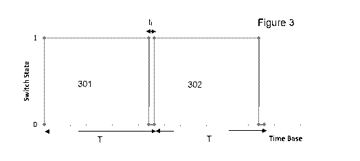
Figure 3 shows a switching duty cycle for a plurality of resistive elements
5 according to one or more embodiments of the present invention.
Figure 4 shows a switching duty cycle for a plurality of resistive elements
according to one or more embodiments of the present invention.
Embodiments
Figure 1 shows a schematic of a typical wind turbine 10 which includes
embodiments of wind turbine blades 19 according to the present invention. The
wind turbine 10 is mounted on a base 12 which may be onshore foundations or
off-shore platforms or foundations. The wind turbine includes a tower 14
having a
number of tower sections. A nacelle 16 is located and attached to the top of
tower
14. A wind turbine rotor, connected to the nacelle 16, includes a hub 18 and
at
least one wind turbine blade 19, where in Figure 1 three wind turbine blades
are
shown although any number of wind turbine blades 19 may be present depending
on the design and implementation of the wind turbine 10. The wind turbine
blades
19 are connected to the hub 18 which in turn is connected to the nacelle 16
through a low speed shaft which extends out of the front of the nacelle 16.
With reference to Figure 2, a wind turbine blade 201 may have attached
thereto, or
embedded within, a plurality of ETH elements 202 as part of an ETH system for
generating heat to substantially prevent or remove ice accretion from the wind
turbine blade 201.
Each of the plurality of ETH elements 202 is connected to a power supply 203
via
a bank of electrical contacts 204, such as an electrical relay. Each
electrical
contact 204 is operatively coupled to one or more predetermined ETH elements
202 in order to switch the predetermined ETH elements 202 on and off. A sensor
205 is connected to ETH system to measure the voltage supplied to the ETH
CA 03066931 2019-12-11
WO 2019/001669
PCT/D1(2018/050160
6
system. The sensor 205 may be a voltage sensor to measure the voltage directly
or a current sensor to determine the voltage based on the current, where
either
can be used to measure the voltage supplied to the ETH system.
Depending on environmental or icing conditions a predetermined number or
pattern of ETH elements 202 are activated according to a predefined switching
duty cycle. The switching duty cycle (e.g. switching on and off relays over a
period
of time) enables a power distribution across the ETH elements attached to, or
embedded within, the blade in a predefined manner. During a switching duty
cycle
any number of the ETH elements 202 may be switched on so as to generate heat
in the predetermined sections of the blade based on the heating requirements
at
that given time.
A switching duty cycle may be for any predetermined time period, e.g. 10
seconds,
20 seconds, 30 seconds, and so on, suitable for controlling the ETH elements
as
required for generating the necessary heat at the required locations in the
wind
turbine blade. During the switching duty cycle predetermined any number of
resistive elements 202 may be switched on and off based on a predefined cycle.
Each ETH element 202 is switched on and off from the power supply via the
corresponding electrical contact 204 according to the predefined switching
duty
cycle. As such, when the electrical contact 204 for a given ETH element 202 is
connected, i.e. switched on, the corresponding ETH element 202 receives
electrical power as it is connected to the power supply, which causes heat to
be
generated by the ETH element 202. In contrast, when the when the electrical
contact 204 for a given ETH element 202 is disconnected or open, i.e. switched
off, the corresponding ETH element 202 does not receive any electrical power
from the power supply.
During operation of the ETH system the voltage supplied may fluctuate which
can
cause the ETH elements of the ETH system to generate more heat than they are
expected or designed to generate. The ETH system may be supplied from the
grid to which the wind turbine is connected or supplied from the electrical
power
CA 03066931 2019-12-11
WO 2019/001669
PCT/D1(2018/050160
7
generated by the wind turbine where, in both cases, the supplied voltage may
fluctuate above a predefined design voltage. Therefore, in order to compensate
for, or to normalize the power output of the ETH system when, fluctuations in
the
supply voltage occur above a predefined design voltage, it has been identified
that
a variable time off period can be inserted within a switching duty cycle or
between
two consecutive switching duty cycles.
With reference to Figure 3, a variable time off period can be inserted within
a
switching duty cycle. Figure 3 shows two switching duty cycles 301, 302 for a
predetermined plurality of ETH elements. The ETH elements controlled by the
switching duty cycle 301, 302 may be all of the ETH elements or a subset of
the
total number of ETH elements, for example, the ETH elements in a particular
zone
or area of the blade such as the leading edge.
In this example of Figure 3, all of the plurality of ETH elements are to be
switched
on during the switching duty cycle 301 and also during the subsequent
switching
duty cycle 302.
In order to normalize the power output of the heating system when the supplied
voltage fluctuates above a predefined design value during the first duty cycle
301
a variable time based enforced off period ti is inserted during the first
switching
duty cycle 301. The duration of the variable time based enforced off period ti
is
variably adjusted proportionally based on the measured voltage supply to
compensate for any fluctuation in the voltage.
The supply voltage is constantly measured, or measured at predetermined times,
and any fluctuation above the predefined design voltage value is used to
determine the required variable time based enforced off period ti to be
inserted
within the switching duty cycle. In this example of Figure 3, the variable
time
based enforced off period ti is inserted towards the end of the duty cycle
301,
however, as will be appreciated the variable time based enforced off period ti
may
be inserted at a different point in the swutching duty cycle.
CA 03066931 2019-12-11
WO 2019/001669
PCT/D1(2018/050160
8
The duration of the variable time based enforced off period ti to be inserted
within
the switching duty cycle may be determined by the following:
VD2
ti = T(1 ¨
wherein:
ti = Duration of the variable time based enforced off period;
VD = Predefined Design Voltage;
T = Total Switching Duty Cycle Time;
VI = Measured Voltage supply.
The determined variable time off period ti is then inserted within the total
time T of
the switching duty cycle 301 to compensate for the voltage fluctuations in the
measured supply voltage.
With reference to Figure 4, a variable time off period can be inserted between
consecutive switching duty cycles. Figure 4 shows two switching duty cycles
401,
402 for a predetermined plurality of ETH elements. The ETH elements controlled
by the switching duty cycle 401, 402 may be all of the ETH elements or a
subset of
the total number of ETH elements, for example, the ETH elements in a
particular
zone or area of the blade such as the leading edge.
In this example of Figure 4, all of the plurality of ETH elements are to be
switched
on for the entire period T of the switching duty cycle 401 and also for the
entire
period T of the subsequent switching duty cycle 402.
In order to normalize the power output of the heating system when the supplied
voltage fluctuates above a predefined design value a variable time based
enforced
off period ti is inserted between the two switching duty cycles 401, 402. The
duration of the variable time based enforced off period ti is variably
adjusted
proportionally based on the measured voltage supply to compensate for any
fluctuation in the supply voltage.
CA 03066931 2019-12-11
WO 2019/001669
PCT/D1(2018/050160
9
The supply voltage is constantly measured, or measured at predetermined times,
and any fluctuation above the predefined design voltage value is used to
determine the required variable time based enforced off period ti to be
inserted
between the consecutive switching duty cycles.
The duration of the variable time based enforced off period ti to be inserted
within
the switching duty cycle may be determined by the following:
2
ti = T(¨vD2 ¨1)
wherein:
ti = Duration of the variable time based enforced off period;
VD = Predefined Design Voltage;
T = Total Switching Duty Cycle Time;
Vi = Measured Voltage supply.
The determined variable time off period ti is then inserted between the two
switching duty cycle 401, 402 to compensate for the voltage fluctuations in
the
measured supply voltage.
The predefined design voltage described hereinabove may be set at the nominal
voltage, e.g. the expected designed voltage, for the ETH system or may be set
at
a voltage below the nominal voltage. The design voltage may be set at a
voltage
lower than the nominal voltage (for example, between a minimum voltage for the
ETH system and the nominal design voltage) in order to take into account any
periods of under voltage, e.g. periods where the supply voltage is below the
expected supply voltage, and/or to provide a safety margin for the operation
of the
ETH system, and/or to enable a higher power output ETH element to be used but
at a lower voltage than can be supplied to the ETH system.
CA 03066931 2019-12-11
WO 2019/001669
PCT/D1(2018/050160
Therefore, the present invention advantageously enables the ETH system to
compensate for supply voltage fluctuations in order to normalize the power
output
of the ETH system and prevent any damage to the ETH system caused by supply
voltage fluctuations.
5
The examples and embodiments described above are for example purposes only,
and it will be appreciated that features of different embodiments or examples
may
be combined with one another. Embodiments of the present invention have been
described, by way of example only, and many modifications or changes may be
10 made to the embodiments and be within the scope of the appended claims.