Note : Les descriptions sont présentées dans la langue officielle dans laquelle elles ont été soumises.
CA 03068644 2019-12-30
Method for analyzing the operating state of a cutting unit and cutting unit
Description
The invention concerns a method and a cutting device for analyzing the
operating con-
dition of a cutting device of a harvesting machine, such as a combine
harvester.
In today's harvesting machines, the analysis of the operating states of
individual com-
ponents of harvesting machines is becoming increasingly important. In order to
in-
.. crease harvesting performance, for example, the aim is to maximize the
travel speed
of the harvester without risking blockages in the crop flow. For this purpose,
for exam-
ple, the determination of the current crop flow is decisive in order to
regulate it as far
as possible to a maximum value depending on the stock density of the crop. The
sen-
sors required to determine the crop flow are usually located in subsequent
arranged
components of the harvester for processing the cut crop or in conveyor systems
of the
harvester.
US 2016/0084987 Al proposes to install sensors in the attachment of a combine
har-
vester to determine the yield quantity and its variability in order to obtain
measured
values about the operating status, such as the crop flow rate, as early as
possible
during the harvesting process. The sensors can, for example, be torque sensors
of
rotating cutting tools. Using the data obtained with these sensors, a
geographical map
can be produced that records the crop density in the field for each
geoposition of the
crop. This data can then be used to adjust the application of seeds and
fertilizer, as
.. well as to adjust or control power when harvesting again.
The object of this invention is to provide a method and a cutting device for
analyzing
the operating condition of the cutting device of a harvesting machine which is
particu-
larly suitable for reciprocating mowing knives.
The object is met by a method for analyzing the operating state of a cutting
device for
mowing crop, the cutting device having at least one mowing knife which is
driven in
reciprocating manner in a stroke direction, and the mowing knife having
cutting edges
which interact with counter cutting edges of the cutting device, with the
following
CA 03068644 2019-12-30
2
method steps:
Detecting of a signal representing the stroke position of the mowing knife,
Detecting a signal representing the knife force for driving the mowing knife
as a func-
tion of the stroke position, and
Determination of crop and/or cutting system properties on the basis of an
evaluation
of the signal representing the knife force as a function of the stroke
position.
In this context, the operating condition of the cutting device in the narrower
sense is to
be equated with the crop and/or cutting system characteristics and may also
include
further characteristics of the cutting device beyond these. The cutting system
com-
prises the mowing knife and the components carrying the counter cutting edges,
such
as mower fingers or a stationary or moving counter knife. In principle, it is
also con-
ceivable that a finger bar carrying the mowing fingers is moved relative to
the mowing
knife.
The knife force can either be the force required to drive the mowing knife as
a whole,
i.e. a force that could be measured, for example, with a force sensor between
a drive
to drive the mowing knife and the mowing knife itself. In the sense of the
invention,
however, the term "knife force" may also refer to individual knife force
components,
.. such as the sum of friction force and cutting force, whereby knife force
components
may be disregarded due to mass inertia forces and natural vibrations of the
mowing
knife.
The signal representing the stroke position of the mowing knife can be, for
example,
.. from a position sensor on the mowing knife or a component moving in a
reciprocating
matter with the mowing knife. It is also possible to determine the stroke
position on the
basis of a rotary position of a rotating drive element for driving the mowing
knife.
For example, the signal representing the knife force for driving the mowing
knife can
.. be a measurement signal from a force sensor between a back and forth
(reciprocating)
moving drive element for driving the mowing knife and the mowing knife. It is
also
conceivable that a torque sensor is provided on a rotating drive element to
drive the
mowing knife, which is used to determine the drive torque. The drive torque
can be
converted into the knife force or directly used as the signal representing the
knife force
CA 03068644 2019-12-30
3
to drive the mowing knife if the drive torque changes directly proportional to
the knife
force. The drive power, which can also be used for further evaluation, can
also be
derived from the values determined in this way.
A reciprocating mowing knife has different operating characteristics in
different stroke
positions during a stroke. For example, the force required to drive the mowing
knife
and the power consumption in the reversing ranges for reversing the drive
direction
are different from those in the other ranges. There are also stroke ranges in
which the
crop is cut and the knife force is correspondingly high, and stroke position
ranges in
which no cutting takes place and the knife force is correspondingly low. For
example,
the force required to drive the mowing knife or the drive power in different
cutting po-
sition ranges of several strokes can provide information for analyzing the
operating
condition of the cutting device.
The determination of crop and/or cutting system properties can comprise in one
em-
bodiment of the method one property from the group consisting of stock density
of the
crop, crop type, crop moisture, weed components, collision, wear condition of
the cut-
ting device and defect of the cutting device.
With the aid of data on the stock density of the crop, crop type and/or crop
moisture,
the power consumption or the required drive power of units of the harvesting
machine
such as a threshing unit or chopper unit, which are located in the crop flow
direction
downstream of the cutting device, can be predicted and/or fed into a control
loop for
regulating the crop flow.
This data can also be used to control the travel speed of the harvester. With
decreasing
crop density, the travel speed can be increased and with increasing crop
density, the
travel speed can be reduced in order to always ensure a crop flow that is as
uniform
as possible and thus a constant load on the harvesting machine's crop
processing
units.
The stroke movement of the mowing knife can be divided into different stroke
position
ranges over the entire stroke of the mowing knife, whereby a distinction can
also be
made between stroke position ranges in a first stroke direction and stroke
position
CA 03068644 2019-12-30
4
ranges in a second stroke direction.
In particular when a mowing knife is used having a plurality of cutting edges
cooperat-
ing with counter cutting edges of the cutting device for cutting the crop, it
may be pro-
vided that those stroke position ranges in which the cutting edges of the
mowing knife
perform a cut of the crop with the counter cutting edges are defined as
cutting ranges.
The variance of the stock density of the crop can thus be determined by
analyzing
measurements of the knife force in cutting ranges taken one after the other.
The higher
the crop density of the crop, the higher the force (knife force) or power
required to drive
the mowing knife, so that the variance of the crop density can be inferred
from the
change in knife force in successive cutting ranges. It is also possible to use
reference
data for certain crop types in order to be able to determine an absolute value
of the
stock density in addition to the variance of the stock density.
The counter cutting edge of a cutting device are usually located on the mowing
fingers
or on the knife blades of a counter knife. The stroke position ranges in which
the cutting
edges of the mowing knife are guided past or through the mowing fingers or the
knife
blades of the counter knife without cutting the crop can be defined as over-
stroke
ranges.
In particular, when using mowing fingers with upper and lower parts which form
a knife
gap through which the mowing knife passes, the knife gap is cleaned or freed
of any
uncut crop which may have been drawn in during this over-stroke range.
If, in the over-stroke range, a higher knife force is required to drive the
mowing knife
than in previous measurements or compared to reference values, it can be
concluded
that an increased number of crop components were drawn between the knife
blades
moving against each other or into blade gaps of mower fingers and thus not
cut. This
may be due, for example, to increased moisture in the crop or other components
in the
crop to be cut, such as weeds.
In addition, those stroke position ranges in which the cutting edges of the
mowing knife
CA 03068644 2019-12-30
are moved between two adjacent counter cutting edges or mower fingers can be
de-
fined as cut-independent ranges. In these areas there is neither a cut of crop
nor a
cleaning of a blade gap from mowing fingers.
5 If there is increased power consumption across the cut-independent
ranges, this may
indicate a collision or defect in the cutting device.
When determining the knife force (or power), the average and/or maximum knife
force
(or power) for driving the mowing knife in certain stroke positions can be
determined.
Exceeding a certain maximum limit value may indicate a collision of the
cutting device
with a non-cuttable object, such as a stone, a reel tine or other foreign
object.
According to one embodiment of the method the average and/or maximum knife
force
for driving the mowing knife in different stroke position ranges of a single
stroke of the
mowing knife is compared. It is also possible to record the knife force curve
over a
single entire stroke of the mowing knife. This evaluation of the knife force
curve over a
single stroke or the comparison of the knife force in individual stroke
position ranges
of a single stroke can provide information about the crop properties or the
condition of
the cutting device.
According to another embodiment the average and/or maximum knife force for
driving
the mowing knife in identical stroke position ranges of different strokes of
the mowing
knife is compared. Thus, different successive strokes are compared with each
other in
terms of how the knife force runs in the individual stroke position ranges.
Likewise, it
is possible to determine a knife force curve over the individual strokes,
whereby the
successive knife force curves are compared with each other. Thus a temporal
variance
of the knife force can be analyzed.
According to a further embodiment of the method the average and/or maximum
knife
force for driving the mowing knife in a stroke position range is compared with
a refer-
ence value for this stroke position range. As an alternative or in addition,
the knife force
curve of an individual stroke can also be compared with a reference knife
force curve.
CA 03068644 2019-12-30
6
The object is further solved by a cutting device for an agricultural
harvesting machine
for mowing crop, comprising: at least one mowing knife reciprocally driven in
a stroke
direction; a drive driving the mowing knife; a sensor for detecting a signal
representing
the stroke position of the mowing knife; a sensor for detecting a signal
representing
the knife force for driving the mowing knife; and a processing unit for
evaluating and
recording the detected signals.
In general, the cutting device may have several mowing knives and at least one
sensor
per mowing knife for detecting a signal representing the stroke position of
the mowing
knife and at least one sensor for detecting a signal representing the knife
force for
driving the mowing knife.
A single processing unit can be assigned to each mowing knife. In one
embodiment,
the individual processing units of each mowing knife can be connected to a
central
processing unit of the cutting device for data exchange.
The invention is explained in more detail below using the drawings.
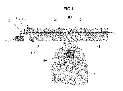
Figure 1 is a schematic top view of a combine harvester in the area of the
cutting
device with a mowing knife,
Figure 2 is a schematic top view of a combine harvester in the area of the
cutting
device with two mowing knives,
Figure 3 is a schematic top view of a double finger and a knife blade in
different
stroke positions in a cut-independent range,
Figure 4 is a schematic top view of a double finger and a knife blade in
different
stroke positions in a cutting range,
Figure 5 is a schematic top view of a double finger and a knife blade in
different
stroke positions in an over-stroke range,
Figure 6 is a partial longitudinal section through the cutting device in the
area of a
CA 03068644 2019-12-30
7
mower finger,
Figure 7 shows a control loop for controlling the engine load of a harvester,
and
Figure 8 shows a cascaded control loop for controlling the engine load of a
harvester.
Figures 1 and 2 each show a schematic top view of an agricultural harvester in
the
form of a combine harvester 8, which can be moved in a driving direction F
parallel to
a center axis M of the combine harvester 8. The combine harvester 8 is shown
in a
section in a front area where the combine harvester 8 has a cutting device 1
for mowing
crop. The cutting device 1 shown in Figure 1 and Figure 2 differ in that the
cutting
device 1 in Figure 1 has one mowing knife 2 and the cutting device 1 in Figure
2 has
two mowing knives 2, 2'. The mowing knives 2, 2' are driven back and forth in
a recip-
rocating manner along a drive axis A. The drive axis A runs at a right angle
to the
center axis M and thus transversely to the driving direction F. The mowing
knives 2, 2'
as shown in Figure 2 are arranged on both sides of the central axis M and can
each
be driven separately.
The mowing knives 2, 2' of both versions as shown in Figure 1 and Figure 2
each have
knife blades 3 which interact with counter cutting edges not shown here to
make a
cutting movement when the mowing knife 2, 2' is moved back and forth.
The mowing knife 2 of the cutting device 1 of the embodiment according to
Figure 1 is
connected to a drive 4 by means of which the mowing knife 2 is driven back and
forth.
Drive 4 may include, for example, a gearbox, such as a toothed gear, a
traction drive
or similar transmission. The drive 4, in turn, can be driven mechanically,
hydraulically
or electrically via a drive motor of the combine harvester 8.
At least one sensor 5 is provided on cutting device 1 to determine the knife
force. The
sensor can, for example, be a force sensor or a torque sensor, whereby other
meas-
ured values, such as power, can also be inferred from the directly measured
values.
In addition, a sensor 6 for determining the stroke position of the mowing
knife 2 is
arranged on cutting device 1.
CA 03068644 2019-12-30
8
The measured values determined by sensors 5 and 6 are transmitted to a
processing
unit 7 for drive 4. The measured values are recorded and evaluated in
processing unit
7. The processing unit 7 may also be connected to a control unit 9 of combine
harvester
8. This can be used, for example, to intervene in the drive control of the
units pro-
cessing the crop or in the motor control, for example to adjust the travel
speed of the
combine 8.
In Figure 2, one drive 4, 4', one sensor 5, 5' for determining the knife force
and one
sensor 6, 6' for the stroke position of the respective mowing knife 2, 2' are
provided for
each mowing knife 2, 2'. The sensors 5, 5', 6, 6' for a mowing knife 2, 2' are
each
assigned to a processing unit 7, 7'. As shown, a central processing unit 10
can also be
provided for the cutting device 1, which is connected to the two processing
units 7, 7'
for the drive 4, 4'. The central processing unit 10 for the cutting device 1
can in turn be
connected to the control unit 9 of the combine harvester 8. However, it is
also possible
that the processing units 7, 7' of the drives 4, 4' are directly connected to
the control
unit 9 of the combine harvester.
Data lines 11 are available for data transmission between the individual
processing
units 7, 7', 10 and the control unit 9.
In one of the processing units 7, 7', 10 of the cutting device 1, the knife
force for driving
the respective mowing knife 2, 2' in certain stroke positions or stroke
position ranges
is determined or calculated on the basis of the measured values of the sensors
5, 5',
6, 6'. For this purpose, the stroke movement of the mowing knives 2, 2' may be
divided
into different stroke position ranges over the entire stroke of the respective
mowing
knife 2, 2'.
Figures 3 to 5 show different representations of the cutting device 1 in the
area of a
double finger 12, which has two fingers 13, 14 protruding in the driving
direction F, the
two fingers 13, 14 being arranged laterally spaced from each other. As shown
in Figure
6, the double finger 12 also has an upper part 15 and a lower part 16, which
are firmly
connected to each other. At the rear end of the cutting device, viewed in the
driving
direction F, the upper part 15 and the lower part 16 are connected to a cutter
bar 18 of
the cutting device via fastening screws 17.
CA 03068644 2019-12-30
9
A central part 19 is arranged between the upper part 15 and the lower part 16,
a knife
gap 21 being formed between the central part 19 and an upper web 20 of the
upper
part 15. The mowing knife 2 is guided in the blade gap 21.
The mowing knife 2 has knife blades 22 which are guided in the knife gap 21.
The knife
blades 22, viewed in drive axis A, have cutting edges 23, 24 (Figures 3 to 5)
on both
sides, which interact with counter cutting edges 25, 26 of the fingers 13, 14
to cut crop.
Basically, other fingers can also be used, such as simple fingers with only
one finger
facing forward, or multiple fingers with more than two fingers. Likewise,
fingers can be
used which do not have an upper part, but only a lower part. In addition, as
an alterna-
tive to the fingers, a counter knife can also be provided, which is similar to
the mowing
knife and is equipped with corresponding knife blades.
Figures 3 to 5 show to simplify matters only the double finger 12 and a knife
blade 22
in different stroke positions relative to the double finger 12, whereby the
upper part of
the double finger 12 is not shown for the sake of clarity. In each of Figures
3 to 5, the
knife blade 22 is shown in two stroke positions, one in an initial position,
in which the
knife blade is shown with solid lines, and the other in an end position, in
which the knife
blade 22 is shown with broken lines. The respective starting positions and end
posi-
tions define the start and end of different stroke position ranges.
From Figure 3 to Figure 4 and to Figure 5, a complete stroke of the mowing
knife is
shown, in a stroke direction H parallel to the drive axis A. Figure 3 shows a
first stroke
range H1 from a turning point arranged on the right in Figure 3, in which the
direction
of movement of the mowing knife and thus of the knife blade 22 of the mowing
knife
shown is reversed, i.e. to the left in the illustration. Starting from the
right turning point
where the knife blade 22 is shown with solid lines, the knife blade 22 is
moved to a first
intermediate position where the knife blade 22 is shown with broken lines.
Over this
first stroke range H1, which can also be described as a cut-independent range,
the
cutting edge 23 of the knife blade 22 at the front in stroke direction H does
not cross
the counter cutting edge 25' of the left finger 14, so that no cut is made.
CA 03068644 2019-12-30
Figure 4 shows a second stroke range H2 from the first intermediate position
shown in
Figure 4 on the right, in which the knife blade 22 is shown with solid lines,
to reaching
a second intermediate position on the left, in which the knife blade 22 is
shown with
broken lines. Over this second stroke range H2, which can also be referred to
as the
5 cutting range, the cutting edge 23 of the knife blade 22 at the front in
stroke direction
H crosses the counter cutting edge 25' of the left finger 14 so that a cutting
movement
takes place.
Figure 5 shows a third stroke range H3 from the second intermediate position
shown
10 .. in Figure 5 on the right, in which the knife blade 22 is shown with
solid lines, to reaching
a left turning point, in which the knife blade 22 is shown with broken lines.
At left turning
points, the stroke direction changes from a left movement to a movement back
to the
right. This third stroke range H3, which can also be referred to as the over-
stroke range,
guides the mowing knife 2 past or through the left finger 14 without cutting
the crop.
Figure 7 shows a conventional exemplary control loop for controlling the
engine load.
The reference value 27 is the nominal value of the motor load and the feedback
28 is
the actual value of the motor load. These two values together result in
control deviation
29, which is fed to a controller for controlling the motor load. Controller 30
outputs a
setpoint as (general) control value 31 for the travel speed. The control value
31 of the
travel speed 31 is fed to an actuator 32 for controlling the travel drive,
resulting in an
actual value of the travel speed 33 (as control value). Due to the cutting
device settings,
crop characteristics and working width of the cutting device used, which are
the dis-
turbance value 34, the throughput of the cutting device over the controlled
system 35
.. is 36. The throughput of the harvesting machine 37 in the processing units
downstream
of the cutting device, such as a threshing unit, can only be determined after
a dead
time 38, as the crop must first be transported from the cutting device to the
threshing
unit.
The controlled value of the throughput of the harvester 37 is fed back via the
measuring
element 39 of the main engine as the actual engine load value 28.
Harvesters, in particular combine harvesters, are limited in their threshing
capacity by
CA 03068644 2019-12-30
11
the engine power. In order to cope with local increases in stock density, a
power re-
serve must be maintained for the engine so that threshing elements do not clog
up but
can absorb stock density peaks. Due to the transport dead time of the crop
from the
cutting device to the threshing organ, conventional regulations, as shown in
Figure 7,
only react to changed crop densities when the crop has already arrived in the
threshing
organ. The throughput of the harvesting machine is regulated here. The travel
speed
serves as the control value.
Figure 8 shows an adapted regulation. The control loop is initially designed
in the same
way as the control loop shown in Figure 7. However, the throughput of cutting
device
36 is already reduced in a cascaded control system. The sensors described
above on
the cutting device, which are specified here as measuring element 40, are used
for this
purpose. These output, for example, the required power of the knife drive 41.
This is
fed to a controller 43 with a nominal value of the knife drive power 42 for
controlling
the cutting system load. The controller 30 for the motor load does not output
a travel
speed nominal value, but the nominal value 42 for the knife drive. The
controller for the
editing system load 43 finally outputs the nominal value for the travel speed
31.
This results in a control loop that records stock fluctuations before they
affect the
threshing organ and can therefore react more quickly.
CA 03068644 2019-12-30
12
Reference numerals list
1 Cutting device
2, 2' Mowing knife
3 Knife blade
4, 4' Drive
5, 5' Sensor for knife force
6, 6' Sensor for stroke position
7, 7` Processing unit for the drive
8 Combine harvester
9 Combine harvester control unit
Processing unit for the cutting device
11 Data line
12 Double finger
13 Finger
14 Finger
Upper part
16 Lower part
17 Fixing screws
18 Cutter bar
19 Middle part
upper web
21 BaIde gap
22 Knife blade
23 Cutting edge
24 Cutting edge
25, 25' Counter cutting edge
26, 26' Counter cutting edge
27 Reference variable (nominal value)
CA 03068644 2019-12-30 .
13
28 Feedback (actual value)
29 Control deviation
30 Controller
31 Control value for travel speed
32 Actuator
33 Actual value of the travel speed
34 Disturbance value
35 Controlled system cutting device
36 Cutting device throughput
37 Harvester throughput
38 Dead time
39 Measuring element
40 Sensors
41 Power actual value
42 Power nominal value
43 Controller cutting system load
A Drive axis
F Driving direction
H1, H2, H3 Stroke position range
M Center axis