Note : Les descriptions sont présentées dans la langue officielle dans laquelle elles ont été soumises.
CA 03068703 2019-12-30
WO 2019/013644 1 PCT/N02018/050181
A METHOD, AN APPARATUS AND A SYSTEM FOR ALIGNING PIPES COAXIALLY
The present invention relates to a method, for aligning pipes coaxially. More
specifically the inven-
tion relates to a method, an apparatus and a system for aligning a movable
first pipe coaxially with
a substantially stationary second pipe to prepare a threaded end portion of
the first pipe for en-
gagement with a threaded end portion of the second pipe.
The pipes may typically, but not exclusively, be casing pipes or drill pipes
used in the oil and gas
industry wherein a plurality of individual pipes, so-called pipe joints, form
a pipe string.
A person skilled in the art will appreciate that a drill pipe is normally
provided with relatively rough
and robust threads, while a casing pipe is normally provided with fine threads
being vulnerable to
damages. The method according to the present invention is primarily directed
towards a method for
connecting joints or sections of casing pipes at a drill floor, but the method
is also suitable for con-
necting drill pipes.
The individual joints of casing, typically having a length of about 12 meters,
are secured to each
other to make up a casing string being lowered into a well of an oil or a gas
reservoir. When adding
a new joint of casing to a string of casing, the string of casing will be
supported at a rig floor by
means of a wedge or spider having a set of slips that supports the weight of
the casing string.
Typically, a casing elevator provided with clamps is used to collect a new
joint of casing to be se-
cured to the casing string. The casing elevator normally engages a top portion
of the new joint,
preferably just beneath a box section of the joint so that a top portion of
the elevator abuts against
a shoulder of said box section. Such an elevator is normally connected to a
top drive of the rig via
bails providing a hinge connection between the elevator and the top drive. The
bails are stiff rods
typically with ends provided with eyes for receiving connection means arranged
at the elevator and
top drive, respectively. Thus, free hanging bails and the elevator, i.e.
without carrying a new joint of
casing, will due to gravity hang vertically down from the top drive. To be
able to tilt the bails an an-
gle with respect to a vertical axis to effect a horizontal adjustment of the
elevator, a hydraulic cylin-
der is connected to a portion of the top drive and a portion of the bails
between the eyes, as will be
appreciated by a person skilled in the art. The actuation of the hydraulic
cylinder is controlled man-
ually, typically from a driller's cabin.
CA 03068703 2019-12-30
WO 2019/013644 2 PCT/N02018/050181
The elevator with the new joint of casing is lowered until it lands on, and is
supported by, the string
of casing. A casing gripper is then used to rotate the joint of casing so that
a threaded pin portion of
the casing joint is rotated into engagement with a threaded box portion of the
casing string.
A major challenge of such an operation is to make sure that the pin portion of
the casing joint fully
mates with the box portion of the casing string prior to rotating the joint of
casing into engagement
with the string of casing. By the term "fully mates" is meant that the joint
of casing is sufficient coax-
ial with the string of casing to avoid any damages on the threads. The
inventor has experienced
that making a connection when there is a deviation of more than 1 to 1.5
between the longitudinal
axis of the casing string and the casing joint, may cause serious damage to
the threads of the
to pin/box connection. Depending on the damage, the threads may in some
cases be repaired. How-
ever, such a repair is time consuming and therefore costly. In other cases,
both the top pipe joint of
the pipe string and the pipe joint to be connected thereto must be replaced.
A rig, especially an offshore rig, is vulnerable to movement due to for
example wind and waves.
Such a movement represents challenges for the driller and the casing operator
to decide when the
casing joint and the casing string are arranged sufficiently coaxially to
commence the engagement
operation, i.e. to activate rotation of the casing gripper. Oftentimes it is
difficult, or even impossible,
for an operator to decide whether the centre lines of the casing string and
the casing joint are coax-
ially aligned.
There is therefore a need for a method and an apparatus that may provide a
"diagnostic" of the rel-
ative position between the casing string and the casing joint to be connected
to the casing string.
Preferably, the method and the apparatus should provide information to the
driller and the casing
operator whether the connection is ready for commencement or not, i.e. go-
information or no-go-
information.
In accordance with the method, a relative position between the casing string
and the casing joint to
be connected to the casing string is measured by means of triangulation.
Triangulation measure-
ments may for example, but not exclusively, be provided by means of a laser
emitting device by
means of a so-called LIDAR (Light Detection and Ranging) technology.
Laser emitting devices have been used for a variety of purposes in the oil and
gas industry.
Publication EP0471659 Al discloses an apparatus and a method for aligning on a
common axis at
least two spaced-apart elongated members to a known angular relationship. The
apparatus com-
prises: a laser for producing a beam of light; a reflector with a reference
mark thereon; means for
attaching the laser to a first elongated member with said laser directed along
the common axis and
with a first reference mark on a radius from the common axis to said laser;
and means for attaching
said reflector with the mark thereon to the second elongated member with said
reflector perpendic-
ular to the common axis and with a second reference mark on the radius from
the common axis to
CA 03068703 2019-12-30
3
WO 2019/013644 PCT/N02018/050181
said mark on said reflector. The apparatus and method are particularly suited
for aligning the ele-
ments in directional core barrels used for determining the orientation of
cores of rock cut from bore-
holes.
Publications W02014/005187 Al and US 2012/279782 Al disclose a laser alignment
device for a
drill rig having an elongate drill rod, the laser alignment device including a
head unit having at least
a pair of laser emitting devices mounted independently of one another thereon,
each of the laser
devices movable in one plane only and oriented in substantially opposite
directions to one another,
an attachment means to attach the head unit to a drill rig and a length-
adjustable assembly to ad-
just the separation distance between the head unit and the drill rod, wherein
the alignment device
to is used to align at least the azimuth of the drill rod relative to
survey marks.
Publication US 2013/341036 Al discloses an apparatus for aligning a wellhead
or BOP stack and a
mast. The apparatus comprises: a rig carrier; a mast assembly pivotally
mounted to said rig carrier,
said mast assembly moveable between a lowered position and an upright position
with respect to
said rig carrier, said mast assembly extending over a back end of said rig
carrier when raised to
.. said upright position; a top drive mounted on said mast assembly which is
constrained to move
along a fixed axial path; and at least one sensor such as for example a laser
or a sonar sensor, op-
erable for aligning said fixed axial path with said wellhead or BOP stack for
drilling operations.
Publication WO 2013/048260 A2 discloses a method for determining a stickup
height of a pipe or
the position of a pipe joint on the drill floor in order to accurately define
the action point to where a
pipe handling means, such as a roughneck, is to be applied.
Publication US 4747454 discloses a method for aligning a second conduit with a
first conduit
wherein the first conduit is substantially vertically positioned in a borehole
so that an upper end of
the first conduit extends upwardly from the bore hole. The second conduit has
an upper end and a
lower end, the method comprising the steps of: connecting a signal generating
unit to the second
conduit so as to be disposed in close proximity to the upper end thereof, said
signal generating
means adapted to produce a signal in the direction of the lower end of the
second conduit repre-
sentative of a vertical plumb line reference of the second conduit when the
second conduit is sub-
stantially vertically disposed.
The invention has for its object to remedy or to reduce at least one of the
drawbacks of the prior
art, or at least provide a useful alternative to prior art.
The object is achieved through features specified in the description below and
in the claims that fol-
low.
The invention is defined by the independent patent claim. The dependent claims
define advanta-
geous embodiments of the invention.
CA 03068703 2019-12-30
4
WO 2019/013644
PCT/N02018/050181
A first aspect of the invention relates to a method for aligning a movable
first pipe coaxially with a
substantially stationary second pipe to prepare a threaded end portion of the
first pipe for engage-
ment with a threaded end portion of the second pipe. The method comprises the
steps of:
a) determining, by means of triangulation, a position of a centre line of the
second pipe;
b) prior to bringing the threaded end portion of the first pipe in contact
with the threaded end portion
of the second pipe, determining, by means of triangulation, a position of a
central end portion of the
first pipe being closest to the second pipe;
c) calculating direction and amount of any horizontal deviation between the
centre line of the sec-
ond pipe and the central end portion of the first pipe facing the second pipe;
d) outputting a first guiding signal indicative of direction and amount of the
horizontal deviation cal-
culated in step c),
e) moving the first pipe according to the first guiding signal; and then
f) moving the threaded end portion of the first pipe to abut against the
threaded end portion of the
second pipe;
g) determining, by means of triangulation, a first pipe direction vector and a
second pipe direction
vector;
h) calculating direction and amount of any inclination of the first pipe
direction vector with respect to
the second pipe direction vector;
i) outputting a second guiding signal indicative of direction and amount of
inclination calculated in
step h);
j) adjusting the inclination of the first pipe according to the second guiding
signal; and
k) rotating the first pipe so that the threads of the first pipe engage with
the threads of the second
pipe.
In step a), the centre line may be determined by finding peripheral end-
portions of a cross-section
of the second pipe. By assuming that the pipe is circular, the position of the
centre line may be cal-
culated. Further, by assuming the second pipe having vertical orientation,
only one horizontal
measurement needs to be executed. In such a case with one horizontal
measurement of the sec-
ond pipe, a body of the second pipe is measured relatively close to a border
area between the pipe
body and the portion of the pipe provided with threads. By relatively close is
meant for example 25
cm below the border area. However, in the event that the second pipe deviates
from a vertical posi-
tion, for example due to inclination of a floating rig, at least two distant
positions of the second pipe
may be measured to find a direction of the centre line of the second pipe.
In step b), the end portion of the first pipe may be determined in the same
manner as for the "one-
measurement" case for the second pipe.
In steps a) to c) and g) to h), the triangulations and calculations are
preferably determined and cal-
culated by means of a computer.
Steps a) to e) may be repeated one or more times until the first guiding
signal indicates that said
CA 03068703 2019-12-30
WO 2019/013644
PCT/N02018/050181
central end portion of the first pipe is arranged substantially aligned with
the centre line of the sec-
ond pipe. Similarly, steps g) to j) may be repeated one or more times until
the second guiding sig-
nal indicates that the first pipe direction vector is substantially coaxial
with the second pipe direction
vector.
5 In one embodiment, steps g) to k) are repeated at least until a portion
of the threaded end portion
of the first pipe has been rotated into engagement with the threaded end
portion of the second
pipe. This has the effect that any misalignment occurring during commencement
of the engage-
ment may be corrected.
In a manual operation controlled by an operator, at least one of the first
guiding signal and the sec-
t() ond guiding signal may be provided as visual and/or audible signals to
an operator. In one embodi-
ment, the signals may be presented as visual signals on at least one monitor
such as for example a
display device. Alternatively or additionally, the visual signals may be
presented by means of col-
oured lights, such as for example red, yellow and green signals wherein red
signal light may indi-
cate "no-go", while a green signal may indicate "go" with respect to relative
position of the first pipe
with respect to the second pipe.
In an autonomous operation, i.e. an operation controlled by an automatic pipe
handling apparatus
such as a robot, the first guiding signal and the second guiding signal may be
provided as input sig-
nals to the automatic pipe handling apparatus.
The triangulation measurements may be obtained by means of 3D sensor apparatus
selected from
.. the group comprising: laser scanning apparatus, acoustic scanning apparatus
such as a sonar, ra-
dar apparatus, stereo camera, combined with triangulation algorithms, or a
combination of two or
more thereof.
In one embodiment, step a) and step b) may comprise using a laser scanning
apparatus having an
oscillating scanning pattern being substantially perpendicular to a
longitudinal axis of the first pipe
.. and the second pipe. Step g) may comprise using a laser scanning apparatus
having a rotating
scanning pattern wherein the scanning pattern is in a substantially vertical
plane. Alternatively, step
g) may comprise using an oscillating laser scanning apparatus having at least
two scanning pat-
terns being mutually distant and substantially perpendicular to a longitudinal
axis of the second
pipe.
In one embodiment, step a) and/or b) may comprise using a laser scanning
apparatus having a ro-
tating scanning pattern wherein the scanning pattern is in a substantially
vertical plane.
As mentioned introductorily, a new joint of casing to be secured to the casing
string supported at a
rig floor, is typically collected from a storage area by means of a pipe
handling apparatus or system
comprising an elevator hanging from the top drive via bails.
CA 03068703 2019-12-30
WO 2019/013644 6 PCT/N02018/050181
To adjust an inclination of the first pipe according to the second guiding
signal, as stated in step j)
of the method, it may be necessary to move the elevator carrying the first
pipe a certain horizontal
distance.
A horizontal movement of the elevator, and thus the inclination of the first
pipe, is effected by tilting
the bails. A tilting of the bails may typically be effected by means of the
hydraulic cylinder con-
nected to a portion of the bails and a portion of the top drive.
A person skilled in the art will appreciate that the tilting is possible in a
two-dimensional plane only.
The two-dimension tilting plane is an imaginary plane defined by a centre axis
of the bails.
Prior to aligning the first pipe coaxially with the second pipe, the imaginary
plane defined by the
bails must be oriented with respect to the second pipe direction vector so
that the imaginary plane
is substantially perpendicular to the second pipe direction vector. If the
bails are tilted by means of
the hydraulic cylinders when the imaginary plane is not substantially
perpendicular to the second
pipe direction vector, then the first pipe direction vector would not be
aligned with the second pipe
direction vector. The imaginary plane defined by the bails is oriented by
rotating the top drive a cer-
tam n angle, as will be appreciated by the skilled person.
Experience shows that that in most situations, the imaginary plane defined by
the bails does not
have to be adjusted. However, it is sometimes necessary to adjust or reorient
the imaginary plane
to a substantially perpendicular position with respect to the second pipe
direction vector so that the
first pipe direction vector can be sufficiently aligned by tilting the bails
by means of the hydraulic
cylinders operatively connected thereto.
The inventor has surprisingly found that an electronic compass arranged on the
elevator or on the
top drive may provide information concerning a rotation angle of the elevator
required for orienting
the bails prior to or during tilting of the bails by means of the hydraulic
cylinders. Further, the inven-
tor has found that the hydraulic cylinders may be controlled automatically by
means of a propor-
tional valve known per ser and configured for receiving signals from a control
unit.
In one embodiment, the method may comprise obtaining information regarding an
initial orientation
of an imaginary plane defined by bails connecting an elevator carrying the
first pipe, the information
provided by means of an electronic compass. In one embodiment, the method may
comprise:
- prior to step j) determining by means of a signal from an electronic
compass, an orientation of an
elevator carrying the first pipe, the elevator connected to a top drive via
bails, each bail operatively
connected to a hydraulic cylinder for adjusting an inclination of the bails;
- comparing a current orientation with a desired orientation required for
adjusting the inclination of
the first pipe with respect to the second pipe; and
- if the desired orientation deviates from the current orientation, activating
a rotation of the top drive
so that the desired orientation is achieved.
CA 03068703 2019-12-30
7
WO 2019/013644
PCT/N02018/050181
In one embodiment, step j) of adjusting the inclination of the first pipe
according to the second guid-
ing signal, may comprise activating the hydraulic cylinder for adjusting an
inclination of bails in a
pipe handling apparatus by means of a proportional hydraulic valve configured
for receiving a con-
trol signal.
The control signal may be computer generated based on input from the second
guiding signal.
Thus, it should be understood that the electronic compass arranged on the pipe
handling appa-
ratus, for example on the elevator or the top drive, provides information with
regards to the orienta-
tion of the bails and the elevator. Once the signal from the compass provides
information that the
imaginary plane is correctly oriented with respect to the second pipe
direction vector, instruction
signals to the hydraulic proportional valve can be sent so that the hydraulic
cylinder activates a de-
sired tilting of the bails to align the movable first pipe coaxially with the
stationary second pipe.
In one embodiment, the signals to the hydraulic proportional valve may be
initiated manually by an
operator, i.e. activation of the instruction signals is a manual operation.
Preferably, after an initial activation the instruction signals are computer
generated. This has the
effect that the desired inclination of the bails, and thus the alignment of
the first pipe coaxially with
the second pipe may be fully automatic once the compass gives the operator
information that the
imaginary plane is correctly oriented with respect to the second pipe
direction vector.
In one embodiment the signals received from the electronic compass and the
signals to the hydrau-
lic proportional valve are sent/received continuously throughout the step of
adjusting the inclination
of the first pipe with respect to the second pipe.
In a second aspect of the invention there is provided an apparatus for
aligning a movable first pipe
coaxially with a substantially stationary second pipe to prepare a threaded
end portion of the first
pipe for engagement with a threaded end portion of the second pipe, the
apparatus comprising:
- a first triangulation device for determining a position of a centre line of
the second pipe, the first
triangulation device configured for sending a signal to a computer;
- a second triangulation device for determining a position of a central end
portion of the first pipe
being closest to the second pipe, the second triangulation device configured
for sending a signal to
the computer;
- the computer configured for calculating direction and amount of any
horizontal deviation between
the centre line of the second pipe and the central end portion of the first
pipe facing the second
pipe;
- a signal transmitter for outputting a first guiding signal indicative of
direction and amount of the
horizontal deviation calculated by the computer; wherein
- the computer further configured for calculating a first pipe direction
vector and a second pipe di-
rection vector and providing a signal to the signal transmitter for outputting
a second guiding signal
CA 03068703 2019-12-30
WO 2019/013644 8
PCT/N02018/050181
indicative of direction and amount of inclination calculated by the computer.
As mentioned above,
the first triangulation device and the second triangulation device may be a 3D
sensor apparatus se-
lected from the group comprising: laser scanning apparatus, acoustic scanning
apparatus, radar
apparatus, stereo camera, combined with triangulation algorithms, or a
combination of two or more
thereof.
The first triangulation device may be a laser scanning apparatus oscillating
in at least one plane or
level.
The second triangulation device may be a laser scanning apparatus oscillating
in more than one
plane, wherein the planes are at different levels along a length of the first
pipe. In one embodiment
.. the second triangulation device is a rotating laser configured for rotating
with respect to the length
of the first pipe.
In an alternative embodiment, the first and the second triangulation device is
a common triangula-
tion device having a dual rotating or oscillating plane.
The signals may be presented to an operator by means of one of or a
combination of a visible sig-
nal on a monitor, or by means of a signal-emitting device configured for
giving a visual and/or audi-
ble signal.
The apparatus according to the invention may be used as a tool for measuring
the length of the
pipe string while tripping in hole. This is achieved by measuring by means of
the triangulation de-
vices a distance between specific parts of two succeeding pipes and add up a
total length of the
pipe string run in hole, as will be explained in the specific part of the
description.
In a third aspect of the invention there is provided a system comprising the
apparatus according to
the second aspect of the invention, wherein the system comprises an electronic
compass arranged
on a pipe handling apparatus comprising an elevator and bails connecting the
elevator to a top
drive, wherein the compass is configured for sending a signal indicative of a
position of an imagi-
nary plane defined by a centreline of the bails.
In one embodiment the system further comprises a hydraulic proportional valve
configured for acti-
vating hydraulic cylinders for affecting an inclination of the bails with
respect to a vertical axis. In a
preferred embodiment, the hydraulic proportional valve is operated by means of
signals generated
by the computer of the apparatus, the signals being based on the second
guiding signal being in-
dicative of direction and amount of inclination of the first pipe direction
vector with respect to the
second pipe direction vector.
From the above, it should be understood that the compass and the hydraulic
proportional valve will
make the method and the system almost fully automatic, i.e. semi-automatic. A
fully automatic
method and system would require that the rotation of the top drive, i.e.
activating a rotation of the
CA 03068703 2019-12-30
9
WO 2019/013644 PCT/N02018/050181
top drive so that the desired orientation of the bails and thus the elevator,
is also automatic. Such
an automatization is particularly relevant for a pipe handling apparatus
manufactured for use with
the system according to the present invention. An existing pipe handling
apparatus would require
modification to be fully automatic for use with the system according to the
invention. By controlling
the orientation of the top drive manually, the only modification required is
to connect the hydraulic
proportional valve to the hydraulic valve controlling the inclination of the
bails, and attach the elec-
tronic compass to a desired portion of the pipe handling apparatus.
In summary, the electronic compass is used to secure a correct orientation of
the bails and the ele-
vator prior to activating the hydraulic cylinders for aligning the first pipe
directional vector coaxially
.. with the second pipe direction vector, after which the threads of first
pipe is rotated into engage-
ment with the threads of the second pipe. The rotation is provided by means of
a pipe rotating de-
vice known per se.
Thus, in one embodiment the method and system according to the invention can
be easily imple-
mented in existing pipe handling apparatuses substantially without
modifications.
.. The method may further comprise measuring by means of triangulation a
length of a pipe string
while being tripped in hole. This has the effect that an exact length of the
pipe string run in hole is
known without having to measure the length manually.
In the following is described an example of a preferred embodiment illustrated
in the accompanying
drawings, wherein:
Fig. 1 shows a side elevation view of a top portion of casing string
supported through a rig
floor and a casing joint hanging above the casing string, wherein a laser
apparatus is
used to measure relative positions between the casing string and the casing
joint,
and a view of a first signal provided on a monitor indicating a relative
position of the
end portion of the casing joint with respect to the centre line of the casing
string rep-
resented by a bull's eye of the target;
Fig. 2a shows a top view of a laser scanning path towards the casing
string in fig. 1;
Fig. 2b shows a top view of a laser scanning path towards a lower
portion of the casing joint
in fig. 1;
Fig. 3 shows the same as fig. 1, but after an end portion of the casing
joint has been moved
substantially into alignment with a centre line of the casing string;
Fig. 4a shows the casing joint after being lowered into contact with the
casing string, wherein
the laser scanning apparatus is used to determine the direction vector of the
upper
portion of the piping string and the direction vector of the casing joint, and
a view of a
CA 03068703 2019-12-30
WO 2019/013644 10 PCT/N02018/050181
second signal provided on the monitor indicating a relative position of the
inclination
of the casing joint with respect to the centre line of the casing string
represented by a
bull's eye of the target;
Fig. 4b shows an alternative to the embodiment shown in fig. 4a, wherein
the direction vector
of the upper portion of the piping string and the direction vector of the
casing joint is
determined by a means of a third laser scanning apparatus;
Fig. 5a shows the same as fig. 4a, but after the centre line of the
casing joint has been
moved substantially into alignment with a centre line of the casing string,
and rotation
of the casing joint into engagement with the casing string has commenced;
Fig. 5b shows an alternative to the embodiment shown in fig. 5a, wherein
the direction vector
of the upper portion of the piping string and the direction vector of the
casing joint is
determined by means of a third laser scanning apparatus;
Fig. 6a shows a screen shot of an ideal make-up graph;
Fig. 6b shows an unacceptable make-up graph showing a so-called humping
wherein a peak
is above a shoulder; and
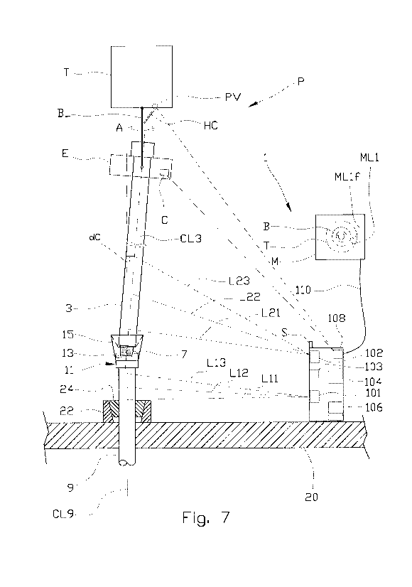
Fig. 7 is based on fig. 4a, but where an elevator is provided with an
electronic compass and
a proportional hydraulic valve wherein the valve is configured for controlling
a cylin-
der for adjusting an inclination of the bails.
Positional specifications, such as over, under, upwards, downwards, upper,
lower, right and left,
refer to the positions that are shown in the figures.
The figures are principle drawings only. For illustrative reasons, the size
ratios between some of
the elements may be somewhat distorted.
Like or corresponding elements are indicated by the same reference numeral in
the various figures,
but, for the sake of exposition, some of the elements may be shown without
reference numerals in
some of the figures.
In figures 1 to 5b, the reference numeral 1 indicates a triangulation
apparatus for use in a method
for aligning a first pipe 3, here shown as a pipe joint 3, with a second pipe
9, here shown as a top
portion of a pipe string 9. The pipe joint 3 and pipe string 9 may for example
be casing pipes or drill
pipes. In the following, the first pipe 3 is denoted a casing joint 3, while
the second pipe is denoted
a casing string 9.
A lower end portion of the casing joint 3 is provided with a pin 5 having
external threads 7. A top
portion of the casing string 9 (and a top portion, not shown, of the pipe
joint 3) is provided with a
CA 03068703 2019-12-30
WO 2019/013644 11
PCT/N02018/050181
box 11 having internal threads 13 mating with the external threads 7 of the
pin 5.
The pipe joint 3 is carried by for example a casing elevator (not shown)
provided with clamps, as
will be appreciated by a person skilled in the art. The casing string 9 is
supported at a rig floor 20
by means of a wedge 22 provided with slips 24 that supports the weight of the
casing string 9.
In the embodiment shown, a top portion of the casing string 9 is provided with
a detachable guiding
collar 15, such as a manual stabbing guide, to provide a guiding means for
guiding the pin 5 of the
pipe joint 3 during lowering of the pipe joint 3 into abutment with the box 11
of the casing string 9.
The pin 5 will hereinafter also be denoted pin portion 5. It should be noted
that the guiding collar 15
is preferable, but not essential. When the pipe joint is a drill pipe stand to
be connected to a drill
string, such a guiding collar is normally not utilized.
The triangulation apparatus 1 comprises laser scanners 101, 102, a computer
104 with a software,
power supply 106 and a transmitter 108 for transmitting signal to at least a
monitor M for presenting
a result of relative positions between the pipe joint 3 and the casing string
9, wherein the positions
are determined by means of triangulation and calculated by means of the
computer 104 with soft-
ware. In the embodiment shown, the signal to the monitor M is transmitted via
a cable 110. How-
ever, wireless signal transmission is also conceivable. The power supply 106
is connected to an
internal or an external energy source.
A casing joint 3 to be connected on a top portion of a casing string 9, is
typically moved from a stor-
age area such as for example a so-called mouse hole (not shown) on a rig by
means of an elevator
(not shown), and near to the casing string 9, as shown in fig. 1. The elevator
may be operated
manually or automatically by means of robotics.
In fig. 1, the pipe or casing joint 3 hangs at a higher elevation than a top
portion of the casing string
9 protruding above the rig floor 20, i.e. there is a vertical distance between
the pin portion 5 of the
pipe joint 3 and the box portion 11 of the casing string 9.
Prior to starting the operation, necessary information with regards to
location of the apparatus 1
with respect to the portion of the casing string 9 protruding above the rig
floor, and data filters and
tolerances, are entered into the computer 104 of the apparatus 1 in a manner
known per se. By
means of the data filters, only data acquired within a specific area will be
used. The acquired data
are distances and angles to the objects measured by the laser scanners 101,
102. Thus, data ac-
quired from objects being outside of the specific area will be disregarded
from triangulation calcula-
tions executed by the computer 104.
When the information mentioned above is entered into the computer 104 and at
least when the
casing joint 3 is brought to the position shown in fig. 1, the laser scanners
101, 102 of the triangula-
tion apparatus 1 may be activated to start scanning a portion of the casing
string 9 as indicated by
the lower dotted line L1. This scanning is performed by the first laser 101.
In the embodiment
CA 03068703 2019-12-30
WO 2019/013644 12
PCT/N02018/050181
shown, a centre line CL9 of the casing string 9 is substantially vertical. In
this operational step, it
may therefore be sufficient to obtain data from only one level or elevation of
the casing string 9.
The first laser 101 may therefore oscillate in one level only as indicated in
fig. 2a, to obtain data for
determining, by means of triangulation, calculations the position of the side
portions 9a and 9b of
the casing string 9 and thus provide data for calculating a position of the
centre line CL9 of the cas-
ing string 9. However, in a situation where the casing string 9 is inclined,
for example more than 5-
with respect to a vertical direction, it may be desirable to determine the
centre line CL9 of the
casing string 9 in the same way as will be discussed below with regards to
fig. 4a and fig. 4b
wherein two or more mutually distant levels of the casing string 9 are
measured.
10 Thereafter, or alternatively simultaneously with the scanning of the
casing string 9, a lower portion
of the casing joint 3 is scanned in a similar way by means of a rotating or
oscillating second laser
102, as indicated by the upper dotted line L2 shown in fig. 1 and fig. 2b. It
should be noted that the
dotted line L2 indicates the measurements that are used in calculating the
position of the centre
line CL3 of the lower end portion of pin portion 5 of the casing joint 3. It
should also be noted that
the second laser 102 is configured to cover an area extending below and above
the lower end por-
tion of the casing joint 3. This is advantageous in order to "find" the lower
end portion of the pin por-
tion 5 and thus be able to determine the position thereof by filtering away
any data being above
and below the lower end portion of the pin portion 5. Thus, the second laser
102 may typically be a
laser rotating in a vertical plane or an oscillating laser configured for
scanning in several "horizon-
tal" levels, i.e. providing several horizontal scanlines being mutually
distant.
By means of the software the computer 104 calculates any deviation dH between
the centre line
CL9 of the casing string 9 and the position of the lower end portion of the
pin portion 5 of the casing
joint 3.
A first guiding signal is sent from the computer 104 of the apparatus 1 to a
monitor M indicating the
deviation dH between the centre line CL9 of the casing string 9 and the
position of the lower end
portion of the casing joint 3. In fig. 1, the first guiding signal is
presented as a dot ML2 in a target T,
wherein a bull's eye B on the target T represents the centre line CL9 of the
casing string 9. The dot
ML2 in the target T provides information to an operator with respect both to a
distance and an ori-
entation of the position of the lower end portion of the casing joint 3 with
respect to the target T, i.e.
the centre line CL9 of the casing string 9. Thus, in a manual operation, the
operator receives visual
information for moving the casing joint 3 towards a target position. During
any movement of the
casing joint 3, the measurement and calculation of at least the position of
the lower end portion of
the casing joint 3 continues either continually or at certain time intervals
such as for example, but
not limited to, one measurement every second.
The movement of the casing joint 3 typically continues until the first guiding
signal ML2 indicates
that the central lower end portion of the casing joint 3 substantially crosses
the centre line CL9 of
the casing string 9, i.e. that the dot ML2 is at least within an outer portion
(shown by a dotted line)
CA 03068703 2019-12-30
WO 2019/013644 13 PCT/N02018/050181
of the bull's eye B in the target T. This is indicated in fig. 3 wherein dH
indicated in fig. 1 is close to
zero. Due to the guiding collar 15, the dH indicated in fig. 1 does not have
to be zero. It is adequate
that dH is sufficiently small to allow the pin 5 of the casing joint 3 to be
guided by the collar 15 into
correct position with respect to the box section 11 of the casing string 9
during lowering of the cas-
ing joint 3 into abutment with the box section 11, as shown in fig. 4.
A drill pipe string is normally not provided with a separate guiding collar 15
of the type shown in fig-
ures 1 to 5b. However, a person skilled in the art will appreciate that a box
portion of a drill pipe
string has a "wedge" form for receiving a pin portion of a drill pipe stem.
The alignment discussed above may be regarded as a "course" alignment. Thus,
the course align-
ment is represented by steps a) to f) above.
However, in order to avoid any damage to the threads 7 of the pin 5 and the
threads 13 of the box
11, the casing joint 3 should be fully aligned with the casing string 9, i.e.
the casing joint 3 must be
arranged coaxially with the casing string 9. By the term fully aligned is
meant sufficiently aligned to
avoid any "shearing" or other serious damages to the threads 7, 13 when
rotation of the casing joint
3 commences. The inventor has found that a deviation of up to about 1 between
the centre line
CL3 of the casing joint 3 and the centre line CL9 of the casing string 9, is
acceptable. For a casing
joint 3 having an overall length of 11 meters, a distant end portion (not
shown) of the casing joint 3
may deviate up to about 20 cm from the centre line CL9 of the casing string 9
to be sufficiently
aligned.
A person skilled in the art will appreciate that the maximum acceptable
deviation depends on the
type of threads of the pipes to be screwed together. Other pipes than casing,
such as for example
drill pipes normally having much coarser threads than those of casing pipes,
may be connected
while having a larger deviation than that for casing pipes discussed above.
Fig. 4a and fig. 4b illustrates two alternative ways of finding the deviation
dC between the centre
line CL3 of the casing joint 3 and the centre line CL9 of the casing string 9.
In fig. 4a, a direction vector of a portion of the casing string 9 protruding
from the rig floor 20 is de-
termined by scanning at least two (three shown in fig. 4a) mutually distant
portions L11, L12, L13 of
the casing string 9. This scanning is performed by means of the first laser
scanning apparatus 101.
Similarly, the direction vector of the casing joint 3 is determined by
scanning at least two (three
shown in fig. 4a) mutually distant portions L21, L22, L23 of the casing joint
3. This scanning is per-
formed by means of the second laser scanning apparatus 102. Based on the
triangulation data ac-
quired by the laser scanning apparatuses 101, 102, the direction vectors for
the casing joint 3 and
casing string 9, respectively, are calculated. For simplicity, the direction
vectors for the casing joint
3 and the casing string 9 are denoted CL3 and CL9, respectively.
The purpose of scanning at least two mutually distant portions of each of the
casing joint 3 and the
CA 03068703 2019-12-30
WO 2019/013644 14
PCT/N02018/050181
casing string 9, is to take into account any movement of for example a
floating rig being subjected
to waves. Such a movement may bring the casing string 9 out of an exact
vertical position.
The measurements of the mutually distant portions L21-L23 and L11-L13 of the
casing joint 3 and
casing string 9, respectively, are, in the embodiment shown in fig. 4a,
obtained by scanning first
one portion of the pipe substantially horizontally and then scanning at least
one other portion of the
pipe being mutually distant from the first portion along a longitudinal axis
of the pipe.
By means of the software, the computer 104 calculates any deviation dC between
the centre line
CL9 of the casing string 9 and the position of uppermost scanning portion
indicated by the dotted
line L23 of the casing joint 3.
In the alternative embodiment shown in fig. 4b, the at least two mutually
distant portions described
above may be obtained by means of a single laser scanning apparatus 103 having
a dual rotating
or oscillating plane.
The third laser scanning apparatus 103 (which is shown in figures 4b, 5b and 7
only) is configured
for rotating or oscillating in a vertical plane, while at the same time
rotating or preferably oscillating
in a "horizontal" plane in a similar way as shown in fig. 2a.
From measurements obtained by the third laser scanning apparatus 103, the
centre line CL9 of the
casing string 9 is calculated from data obtained from the mutually distant
portions L31-L33 (corre-
sponding to the mutually distant portions L11-L13 shown in fig. 4a), while the
centre line CL3 of the
casing joint 3 is calculated from data obtained from mutually distant portions
L34-L36 (correspond-
ing to the mutually distant portions L21-L23 shown in fig. 4a).
By means of the software, the computer 104 calculates any deviation dC between
the centre line
CL9 of the casing string 9 and the position of uppermost scanning portion
indicated by the dotted
line L36 of the casing joint 3.
Independent of which one of the embodiments shown in figures 4a and 4b that
are utilized, a sec-
ond guiding signal is sent from the apparatus 1 to the monitor M indicating
the deviation dC be-
tween the centre line CL9 of the casing string 9 and the casing joint 3. Thus,
the second guiding
signal provides information about direction and magnitude of the inclination
of the casing joint 3
with respect to the casing string 9. In fig. 4a and fig. 4b, the second
guiding signal is presented as a
dot ML1 in the target T wherein a bull's eye B on the target T represents the
centre line CL9 of the
casing string 9. In the example shown in fig 4a, or in the alternative
embodiment shown in fig. 4b,
the dot ML1 on the monitor M indicates that the casing joint 3 is inclined to
the right and a bit out of
the drawing plane.
Preferably, the second signal ML1 is visually different from the first signal
ML2, for example by
means of a different colour or pattern. By presenting two visually
distinguishable signals ML1 and
CA 03068703 2019-12-30
WO 2019/013644 15
PCT/N02018/050181
ML2, both signals may be presented simultaneously. Such a simultaneous
presentation may be
particularly desired if the top portion of the casing string 9 is not provided
with the collar 15. Without
the collar 15, the lower portion of the casing joint 3, i.e. the pin 5, may
move horizontally with re-
spect to the box 11 of the casing string 9 before the engagement of the
threads 7, 13 has com-
menced.
Based on the second signal ML1, the operator may move the casing joint 3 until
the second signal
ML1 is within the inner portion bull's eye B, i.e. the inner circle of the
target T. Thus, the triangula-
tion measurements continue either "continually" or at certain time intervals,
such as for example
each second, at least until the direction vector CL3 of the casing joint 3 is
aligned with the direction
vector CL9 of the casing string 9.
The alignment discussed above may be regarded as a "fine" alignment.
Once the direction vector CL3 of the casing joint 3 is aligned with the
direction vector CL9 of the
casing string 9, rotation R of the casing joint 3 with respect to the casing
string 9 may commence
so that the threads 7 of the pin 5 correctly engage with the threads 13 of the
box 11. This is shown
in fig. 5a and in fig. 5b showing an alternative embodiment of fig. 5a.
In figures 1 to 5b, the apparatus 1 is provided with a signal-emitting device
S configured for giving a
visual and/or audible signal to the operator. The signal-emitting device S may
be a "go"/"no-go"-
signal based at least on the second signal ML1 sent from the apparatus 1. For
example: during the
coarse alignment shown in figures 1 to 4a or 4b, the signal-emitting device S
may emit a red light
indicating "no-go" with respect to starting rotation of the casing joint 3
into engagement with the
casing string 9. Such a red light will be emitted until the direction vector
CL3 of the casing joint 3 is
fully aligned with the direction vector CL9 of the casing string 9, i.e. until
the second signal ML1 is
within the inner portion of the bull's eye B of the target T. When the second
signal ML1 is within the
inner portion of the bull's eye B of the target T, the light emitted from the
signal-emitting device S
will change to green light indicating "go" with respect to starting rotation R
of the casing joint 3. In
one embodiment, an audible signal may be issued simultaneously with the green
light. This exam-
ple is one way of providing signals to an operator in addition to the
information provided by the tar-
get T. It should be clear that other alternatives with respect to light and/or
audible signal may be
issued by the signal-emitting device S to provide any "go" or "no-go" signals
to the operator.
In an alternative to an operation manually controlled by an operator, the
signals ML2 shown in fig-
ures 1-3 and ML1 shown in figures 4a and 5a or 4b and 5b, may be used for
controlling an auto-
mated pipe handling apparatus (not shown) known per se. In such an embodiment,
said signals
ML2 and ML1 may additionally be presented visually for example as indicated by
means of the tar-
get T shown in figures 1-5b.
Turning now to figures 6a and 6b showing an ideal make-up graph and an
unacceptable make-up
CA 03068703 2019-12-30
WO 2019/013644 16
PCT/N02018/050181
graph, respectively.
In fig. 6a, which shows a print out of a real measurement, the torque
(vertical axis) is substantially
constant until the engagement meets the so-called shoulder after a number of
turns (horizontal
axis). The print out shows an ideal make-up graph.
Fig. 6b illustrates a so-called "humping" which means that a so-called peak is
above the shoulder.
Possible causes for a humping may arise for example due to misalignment. A
person skilled in the
art will understand that other reasons for such a humping may be too much
thread compound, bad
stabbing or minor thread damage. However, the present invention concerns
avoiding misalignment.
If a connection operation results in a humping, a break out of the connection
is required. After the
break out a cleaning and inspection of at least the threads are required. If
the threads are ac-
cepted, i.e. no damage, the connection can be remade. If the threads are
damaged beyond minor
repair that may be performed in situ, the pipe string 9 must be pulled in
order to replace the upper
pipe of the pipe string 9. The pipe joint 3 must also be replaced in such a
case. A person skilled in
the art will know that this is a time-consuming and thus a costly operation.
In order to control the rotation R of the casing joint 3, the triangulation
measurements preferably
continue at least during the first few rotations R of the casing joint 3, for
example during the three to
five first rotations R. If the measurements reveal any misalignment between
the direction vectors
CL3 and CL9, the operator will halt rotation R and, based on the second signal
ML1, adjust the
casing joint 3 until the direction vectors CL3 and CL9 are again aligned, and
then continue the rota-
tion R. Thus, an operator may have full control of the process in order to
achieve a substantial ideal
make-up graph as shown in fig. 6a. A person skilled in the art will appreciate
that make-up graphs
are important documentation for the making of a pipe string such as for
example a casing string 9.
In a situation where misalignment of the casing joint 3 and the casing string
9 occurs after com-
mencing the rotation R, the signal-emitting device S may be configured for
issuing an alarm signal.
The alarm signal may be a visual and/or an audible signal.
Turning now to fig. 7 showing a system comprising the apparatus 1 shown in
fig. 4a wherein the
first pipe 3 hangs from a pipe handling apparatus P comprising an elevator E
connected to a top
drive T by means of two spaced-apart bails BL (one shown) as will be
appreciated by a person
skilled in the art. At their end portions the bails BL are provided with eyes
for connection to a con-
nection device on the elevator E and top drive T, respectively, for providing
a "hinged", i.e. freely
rotating, connection. The skilled person will further understand that the pipe
handling apparatus P
shown in fig. 7 is very schematic.
Each one of the two bails BL of the pipe handling apparatus P is further
provided with a hydraulic
cylinder HC having ends connected to a portion of the top drive T and a
portion of the bail BL, re-
spectively. The purpose of the hydraulic cylinders HC is to effect an
inclination of bails BL with
CA 03068703 2019-12-30
WO 2019/013644 17 PCT/N02018/050181
respect to a vertical axis as indicated by arrow A. In a neutral position the
bails BL and thus the ele-
vator E hang vertically down from the top drive T.
In the embodiment shown, the elevator E is provided with an electronic compass
C. In an alterna-
tive embodiment (not shown) the electronic compass could be arranged on a
rotatable portion of
the top drive T, or even on one of the bails BL, However, for practical
reasons, the electronic com-
pass C should preferably be connected to the top drive T or the elevator E.
The electronic compass C is configured to indicate an imaginary plane defined
by the two bails BL.
The imaginary plane runs through the elevator E carried by the bails BL.
In the embodiment shown in fig. 7, the imaginary plane defined by the two
bails BL is 900 with re-
spect to the paper plane. This means that the imaginary plane is perpendicular
to the second pipe
direction vector CL9. Thus, by activating the hydraulic cylinder HC, the bails
BL will be inclined. In
the embodiment shown, the hydraulic cylinders HC should be extended so that
the elevator E
urges the first pipe 3 towards left until the first pipe direction vector CL3
is coaxially with the second
pipe direction vector CL9, i.e. dC= 0. However, in some situations the
imaginary plane defined by
the bails BL, may initially be oriented with an angle being different from 90
with respect to the sec-
ond pipe direction vector CL9. In such a situation, an activation of the
hydraulic cylinder HC would
not bring the first pipe direction vector CL3 coaxially with the second pipe
direction vector CL9.
Thus, it would not possible to reduce dC to zero.
The purpose of the electronic compass C is therefore to provide information to
an operator (or input
to the computer with software in a fully automatic version of the system)
regarding the orientation of
the imaginary axis with respect to the second pipe directional vector CL9. In
the embodiment
shown, the electronic compass E is configured for sending a signal to a
transceiver 108 for receiv-
ing and transmitting signal to the monitor M. In fig. 7 the signal ML1i
indicates the signal initially re-
ceived form the electronic compass E. In a semi-automatic system and based on
the initial signal
ML1i (here shown at "4 o'clock") the operator notes that a rotation of the top
drive T is required in
order to bring the imaginary axis to a predetermined position, which in the
embodiment is at "3
o'clock". The operator then activates rotation of the top drive T until the
signal from the electronic
compass E indicates that the imaginary plane defined by the bails BL is
perpendicular to the sec-
ond pipe direction vector CL9, and the initial signal ML1i on the monitor M is
at the predetermined
position, here shown as ML1f at 3 o'clock.
From the above, the skilled person will understand that the electronic compass
E issues signals
"continually", for example each second. The first pipe 3 is now prepared for
being axially aligned
with the second pipe 9 by means of activating the hydraulic cylinder HC of the
pipe handling appa-
ratus P. In one embodiment this alignment may be achieved by controlling the
hydraulic cylinders
HC manually.
CA 03068703 2019-12-30
WO 2019/013644 18 PCT/N02018/050181
However, the inventor has found that the hydraulic cylinder HC may be
controlled automatically by
means of a hydraulic proportion valve PV operatively connected to the
hydraulic cylinders HC. The
hydraulic proportional valve PV is provided with a control device comprising a
receiver for receiving
signals from the transceiver 108 of the apparatus 1. The signals are based on
data prepared by the
computer 104 and software. The data are calculated from input of present
position ML1f and de-
sired position wherein ML1f is within the bull's eye B, i.e. the first pipe 3
is arranged coaxially with
the second pipe 9.
The signals to the hydraulic proportional valve PV are sent "continually"
during this operation, for
example once per second.
When the pipes 3, 9 are aligned, the hydraulic proportional valve PV may be
locked in an open po-
sition which means that the hydraulic cylinder HC is ready for a manual
operation.
The method, apparatus and system according to the present invention solves the
challenge of en-
suring exact alignment of a first pipe 3 with respect to a second pipe 9 prior
to, and in one embodi-
ment also during, commencement of engagement of the threads 7, 13 of the pipes
3,9, irrespec-
tive of a manual or an automatic operation. Tests show that the method
considerably reduces time
spent for each connection, and that damages to the threads of the pipes due to
misalignment dur-
ing engagement are virtually eliminated which again reduces time and costs for
making a pipe
string.
Further, the method and system according to one embodiment of the invention
provides a near fully
automatic pipe handling apparatus substantially without any modification of
existing pipe handling
apparatuses.
As mentioned above, the apparatus 1 according to the invention may be used as
a tool for measur-
ing the length of the pipe string while tripping in hole. This is achieved by
measuring by means of
the triangulation devices (101, 102; 103) a distance between specific parts of
two succeeding pipes
(3, 9) and add up a total length of the pipe string run in hole.
For example, with reference to fig. 7, after the first pipe 3 has been aligned
with the second pipe 9,
i.e. the first pipe direction vector CL3 has been aligned with the second pipe
direction vector CL9,
the detachable guiding collar 15 is removed. Thereafter, the slips 24 are
released from the wedge
22 and the tripping into the hole commences. During tripping, the laser
scanners 101, 102 as
shown for example in fig. 7 or the laser scanner 103 also shown in fig. 7 and
explained above in
connection with fig. 5b, are active. In fig. 7, only the laser scanners 101,
102 are shown active, but
it should be clear that the laser scanner 103 may be used as explained above
in connection with
fig. 5b. The lower shoulder of the box section 11 of the second pipe 9 will be
detected by the laser
scanners 101, 102; or 103 because of the increased diameter with respect to
the dimension of the
pipe below the box section 11. A length of the first pipe 3 will be measured
continually by means of
CA 03068703 2019-12-30
WO 2019/013644 19 PCT/N02018/050181
the laser scanning apparatus 102; 103 until the elevator E is detected. Since
the height of the ele-
vator E is known, a lower shoulder of the first pipe 3 is also known. Thus, a
length between the
lower shoulders of each of the box sections of the pipes 3, 9 are known. This
length is stored in the
computer 104 and added up with corresponding measurements of subsequent pipes
tripped in
hole. Therefore, the apparatus 1 may be used for measuring an exact length of
the pipe string run
in hole.
The height of the elevator E is entered as input to a software of the
computer.
It should be noted that the above-mentioned embodiments illustrate rather than
limit the invention,
and that those skilled in the art will be able to design many alternative
embodiments without depart-
ing from the scope of the appended claims. In the claims, any reference signs
placed between pa-
rentheses shall not be construed as limiting the claim. Use of the verb
"comprise" and its conjuga-
tions does not exclude the presence of elements or steps other than those
stated in a claim. The
article "a" or "an" preceding an element does not exclude the presence of a
plurality of such ele-
ments.
The mere fact that certain measures are recited in mutually different
dependent claims does not
indicate that a combination of these measures cannot be used to advantage.
The invention may be implemented by means of hardware comprising several
distinct elements,
and by means of a suitably programmed computer.