Note : Les descriptions sont présentées dans la langue officielle dans laquelle elles ont été soumises.
CA 03071859 2020-01-30
WO 2019/055765 PCT/US2018/051049
VARIABLE STIFFNESS GUIDE WIRE
CROSS-REFERENCE TO RELATED APPLICATION
[0001] This application claims the benefit of Provisional Application No.
62/558,402, filed September 14, 2017, which is incorporated herein by
reference in its
entirety for all purposes.
BACKGROUND
[0002] The present disclosure is related to intravascular delivery
devices and
more particularly to guide wires configured to include one or more selectively
variable
mechanical properties, such as flexibility.
[0003] Physicians generally require the use of one or more guide wires to
gain
access to and deliver therapeutic and/or diagnostic devices to intravascular
regions
requiring treatment within the body. A relatively flexible guide wire is
selected and
utilized to facilitate navigation through tortuous vasculature. However,
relatively stiff
guide wires are typically utilized during device delivery and deployment
because they
provide the requisite support needed for proper delivery as well as stability
during
deployment. Thus, in some cases, a combination of guide wires is required to
complete
a procedure.
[0004] Abdominal aortic aneurysmal ("AAA") repair is one of many
exemplary
procedures where multiple different guide wires are utilized during the course
of a
medical procedure. For instance, in some AAA cases, three (3) or more
different guide
wires are utilized during the procedure. A first flexible guide wire is used
to initially
navigate the tortuous structure of the vasculature in order to access the
treatment site
within the aorta. Thereafter, a catheter may be advanced over the first
flexible guide
wire. The first flexible guide wire is subsequently removed and replaced with
a stiffer
guide wire that is suitable for deploying a medical device, such as a stent or
stent graft.
In some cases involving the deployment of a bifurcated stent-graft, a third
guide wire is
used to cannulate the contralateral leg of the bifurcated stent-graft. In some
cases, the
first flexible guide wire used to initially navigate the tortuous structure of
the vasculature
lacks the requisite stability needed to facilitate proper deployment.
SUMMARY
[0005] According to one example, ("Example 1"), a medical system includes
a
guide wire assembly that includes a guide wire member including an alloy and
having a
CA 03071859 2020-01-30
WO 2019/055765 PCT/US2018/051049
flexibility that is configured to change when exposed to an electrical
current; and an
insulation material surrounding at least a portion of the guide wire member.
The
medical system further includes a controller electrically coupled to the guide
wire
assembly and configured to cause an electrical current to be selectively
supplied to the
guide wire assembly such that the flexibility of the guide wire assembly
changes in
response to an exposure to the electrical current.
[0006] According to one example, ("Example 2"), a medical system includes
a
guide wire assembly configured to transition between a first configuration and
a second
configuration, wherein a flexibility of the guide wire assembly in the first
configuration
exceeds the flexibility of the guide wire assembly in the second
configuration, the guide
wire assembly including: a guide wire member including an alloy; and an
insulation
material surrounding at least a portion of the guide wire member. The medical
system
further includes a controller electrically coupled to the guide wire assembly
and
configured to cause an electrical current to be selectively supplied to the
guide wire
assembly to cause the guide wire assembly to transition between the first and
second
configurations.
[0007] According to another example, ("Example 3") further to any of the
preceding Examples, the alloy including a phase-changeable alloy.
[0008] According to another example, ("Example 4") further to any of the
preceding Examples, the alloy including nitinol.
[0009] According to another example, ("Example 5") further to any of the
preceding Examples, the guide wire member including a first core member and a
second core member coupled to the first core member the first core member
including
the alloy such that the guide wire member is configured to change its
flexibility when
exposed to the electrical current, wherein the first and second core members
are
coupled to one another at respective first ends of the first and second core
members,
and wherein respective second ends of the first and second core members are
coupled
with the controller.
[0010] According to another example, ("Example 6") further Example 5, one
or
more of the first and second core members extend generally linearly along a
longitudinal axis of the guide wire assembly when exposed to electrical
current.
[0011] According to another example, ("Example 7") further to any of
Examples
or 6, wherein the first and second core members are aligned parallel to one
another.
[0012] According to another example, ("Example 8") further Example 5,
wherein
the second core member is helically coiled about the first core member.
2
CA 03071859 2020-01-30
WO 2019/055765 PCT/US2018/051049
[0013] According to another example, ("Example 9") further to Example 5,
wherein the first and second core members are each helically wound about a
longitudinal axis of the guide wire assembly.
[0014] According to another example, ("Example 10") further to any of
Examples
to 9, wherein the first core member and the second core member are formed from
different materials.
[0015] According to another example, ("Example 11") further to any of
Examples
5 to 10, wherein the first core member and the second core member are formed
from
different alloys.
[0016] According to another example, ("Example 12") further to any of the
preceding Examples, the guide wire assembly varies in flexibility to allow it
to function
for at least two of the following guide wire purposes: tracking, deployment,
and
cannulation.
[0017] According to another example, ("Example 13") further to any of the
preceding Examples, the controller is operable to cause a current to flow
through a first
portion of the guide wire member and wherein the insulation material surrounds
the first
portion.
[0018] According to another example, ("Example 14") a method of making a
medical system includes providing a guide wire member including an alloy;
disposing an
insulation material about at least a portion of the guide wire member to
define a guide
wire assembly, the guide wire assembly having a flexibility that is configured
to change
when exposed to an electrical current; and electrically coupling a controller
to the guide
wire assembly such that the controller is operable to cause an electrical
current to be
selectively supplied to the guide wire assembly such that the flexibility of
the guide wire
assembly changes in response to an exposure to the electrical current.
[0019] According to another example, ("Example 15") a method of treatment
includes: providing a guide wire assembly that includes a guide wire member
having an
alloy and having a flexibility that is configured to change when exposed to an
electrical
current; and an insulation material surrounding at least a portion of the
guide wire
member. The method further includes electrically coupling a controller to the
guide wire
assembly such that the controller is operable to cause an electrical current
to be
selectively supplied to the guide wire assembly; and causing the controller to
supply a
first electrical current to the guide wire assembly to cause the flexibility
of the guide wire
assembly to change from a first flexibility to a second flexibility, wherein
the first
flexibility exceeds the second flexibility.
3
CA 03071859 2020-01-30
WO 2019/055765 PCT/US2018/051049
[0020] While multiple embodiments are disclosed, still other embodiments
will
become apparent to those skilled in the art from the following detailed
description, which
shows and describes illustrative examples. Accordingly, the drawings and
detailed
description are to be regarded as illustrative in nature and not restrictive.
BRIEF DESCRIPTION OF THE DRAWINGS
[0021] The accompanying drawings are included to provide a further
understanding of inventive embodiments of the disclosure and are incorporated
in and
constitute a part of this specification, illustrate examples, and together
with the
description serve to explain inventive principles of the disclosure.
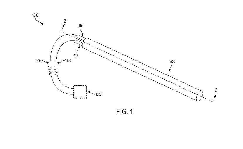
[0022] FIG. 1 is an illustration of a variable stiffness guide wire,
according to
some embodiments.
[0023] FIG. 2 is an illustration of a cross section of the variable
stiffness guide
wire illustrated in FIG. 1 taken along line 2-2, according to some
embodiments.
[0024] FIG. 3 is an illustration of a cross section of a variable
stiffness guide
wire, according to some embodiments.
[0025] FIG. 4 is an illustration of a cross section of a variable
stiffness guide
wire, according to some embodiments.
DETAILED DESCRIPTION
[0026] Persons skilled in the art will readily appreciate that various
aspects of the
present disclosure can be realized by any number of methods and apparatuses
configured to perform the intended functions. It should also be noted that the
accompanying drawing figures referred to herein are not necessarily drawn to
scale, but
may be exaggerated to illustrate various aspects of the present disclosure,
and in that
regard, the drawing figures should not be construed as limiting. In describing
various
examples, the term proximal is used to denote a position along the exemplary
device
proximate to or alternatively nearest to the user or operator of the device.
Proximal may
also be referred to as trailing. The term distal is used to denote a position
along an
exemplary device farthest or farther from the user or operator of the device.
Distal may
also be referred to as leading.
[0027] Various aspects of the present disclosure are directed toward guide
wires
and the like for utilization during medical procedures to locate treatment
regions within a
patient's vasculature and/or facilitate the delivery and deployment of one or
more
medical devices to the treatment region within the vasculature. More
specifically, the
4
CA 03071859 2020-01-30
WO 2019/055765 PCT/US2018/051049
present disclosure relates to guide wire devices and systems, and methods for
using
such guide wire devices and systems.
[0028] In various embodiments, a guide wire system 1000 as illustrated in
FIGS.
1 and 2 includes a guide wire assembly 1100 and a controller 1200 electrically
coupled
to the guide wire assembly 1100. FIG. 2 is a cross sectional view of the guide
wire
assembly of 1100 illustrated in FIG. 1 taken along lines 2-2. The guide wire
assembly
1100 is generally cylindrically shaped having a generally circular cross-
section and
includes an elongate shaft having a proximal end 1102 and a distal end 1104.
Those of
skill in the art will appreciate that the guide wire assembly 1100 may include
any
suitable cross sectional shape. For example, the cross sectional shape may
have
curved aspects, linear aspects, or combinations thereof (e.g., ovular or
polygonal)
without departing from the spirit or scope of the application. Likewise, while
the cross-
section of the guide wire assembly 1100 illustrated in FIG. 2 is generally
uniform along
its length, it should be appreciated that the cross section may vary without
departing
from the spirit or scope of the inventive concepts discussed herein. For
instance, in
various examples, the cross section of the guide wire assembly may taper
longitudinally. In such examples, a distal end may have a different cross
sectional area
than a proximal end and/or an intermediate portion situated between the
proximal and
distal ends.
[0029] In various examples, the guide wire assembly 1100 is generally
insulated
(e.g., electrically and/or thermally) and includes a plurality of core
members, such as
first core member 1110 and second core member 1120. As discussed in greater
detail
below, a flexibility or stiffness of the guide wire assembly 1100 can be
changed or
adjusted during operation (e.g., in-situ) by inducing a current through the
first and
second core members 1110 and 1120 of the guide wire assembly 1100. In various
examples, the flexibility or stiffness of one or more of the first and second
core members
1110 and 1120 of the guide wire assembly 1100 can be controlled through
operation of
the controller 1200. Such a configuration provides that, unlike conventional
designs, the
same guide wire assembly can be utilized during an operation to both locate a
treatment
region within a patient's vasculature and facilitate the delivery and
deployment of one or
more medical devices to the treatment region within the vasculature. For
instance, as
explained in greater detail below, after locating a target treatment region
within a
patient's vasculature, a flexibility of the guide wire can be modified or
adjusted such that
a medical device can be delivered and deployed over the guide wire.
[0030] As mentioned above, the guide wire assembly 1100 includes a plurality
of
CA 03071859 2020-01-30
WO 2019/055765 PCT/US2018/051049
core members, including a first core member 1110 and a second core member
1120. In
various examples, one or more of the first and second core members 1110 and
1120
include, or otherwise formed from, a material that changes one or more
physical
properties when subjected to stimulation from an exterior energy source, such
as an
electrical power source. Thus, in various examples, the first and second core
members
1110 and 1120 include a material that is electrically conductive. Suitable non-
limiting
exemplary materials include, but are not limited to, alloys and phase
changeable alloys
such as nickel-titanium alloys like nitinol (NiTi), doped nickel-titanium
alloys, gold
cadmium alloys, silver cadmium alloys, copper alloys, magnesium alloys, cobalt
alloys,
and the like. In some examples, polymeric material can be melted to achieve
similar
phase changeable properties, as those of skill in the art will appreciate. In
some
examples, these materials are shape settable in that they can transition
between a first
configuration and a second different configuration upon being heated beyond a
critical
temperature (e.g., a temperature at which the material undergoes a transition
between
martensitic and austenitic states), as those of skill in the art will
appreciate. Generally,
the first configuration in which the material is compliant or relatively
flexible in
comparison to the second configuration wherein the material is more stiff or
less
flexible. Relative stiffness or flexibility can be measured using a standard
three-point
bending test or any other test recognized by those in the field as suitable
for a particular
application. For example, ASTM D790 refers to possible non-limiting test
methods for
flexural properties of unreinforced and reinforced plastics and electrical
insulating
materials that could be used to measure relative stiffness and flexibility.
[0031] In various examples, the first and second core members 1110 and
1120
generally include a body having proximal and distal ends. For example, as
shown in
FIG. 2, a first core member 1110 includes a body 1112, a proximal end 1114,
and a
distal end 1116. The first core member 1110 additionally includes an
intermediate
portion 1118 that is situated between the proximal and distal ends 1114 and
1116.
Likewise, as shown in FIG. 2, a second core member 1120 includes a body 1122,
a
proximal end 1124, a distal end 1126, and an intermediate portion 1128
situated
between the proximal and distal ends 1124 and 1126.
[0032] As mentioned above, in various embodiments, a current is induced
through the guide wire assembly 1100 to adjust a flexibility of the guide wire
assembly
1100. In various examples, the first and second core members 1110 and 1120 of
the
guide wire assembly 1100 are electrically coupled together to form a circuit
through
which current can be passed or otherwise induced. While the first and second
core
6
CA 03071859 2020-01-30
WO 2019/055765
PCT/US2018/051049
members 1110 and 1120 may be coupled together at one or more of a plurality of
locations along their length, in various examples, the first and second core
members
1110 and 1120 are electrically coupled together at an end opposite the ends to
which
the electrical leads are coupled. For example, as shown in FIG. 2, distal ends
1116 and
1126 of the first and second core members 1110 and 1120, respectively, are
electrically
coupled together at joint 1130. That is, a joint 1130 is established where the
distal ends
1116 and 1126 of the first and second core members 1110 and 1120 are
electrically
coupled together. Suitable non-limiting exemplary mechanisms and methods for
electrically coupling the first and second core members 1110 and 1120 together
include
welding, soldering, adhering, or banding together with one or more fasteners
including
electrically conductive fasteners as those of skill should appreciate.
[0033] In various examples, the passage of current through the core members
generates heat, which causes a change in one or more physical properties of
the core
members (e.g., flexibility), as discussed in greater detail below. In various
examples,
such heat generation is due in part to the resistance of the material through
which the
current is passing.
[0034] While the core members may be electrically coupled together at one or
more portions or points along their length, in various examples, the core
members may
be additionally or alternatively electrically isolated from one another at one
or more
locations or regions along their lengths. Such a construction provides that
the current
passing through the core members follows a predetermined path, which
facilitates a
guide wire assembly 1100 having a flexibility and structure that can be
selectively
controlled during its use in association with a medical procedure.
[0035] In
various examples, a point or region of a core member is electrically
isolated by disposing or surrounding an insulative material about designated
portions of
the core member. In some examples, the insulative material may be in the form
of a
sleeve that is disposed about the core member or alternatively a sleeve within
which the
core member is inserted. In other examples, the insulative material may be in
the form
of a material that is wrapped about the core member. For instance, an
insulative
material in the form of a tape may be wrapped (e.g., helically or
longitudinally) about the
core member. In other examples, the insulative material may be disposed about
the
core member by way of one or more dipping processes. Similarly, in some
examples,
the insulative material may be disposed about the core member by way of one or
more
spray processes. In some examples, after an insulative material has been
applied to a
core member, one or more processes may be utilized to remove portions of the
7
CA 03071859 2020-01-30
WO 2019/055765 PCT/US2018/051049
insulative material from one or more designated regions, areas, or portions of
the core
member to expose such designated regions, areas, or portions. It should be
appreciated that an insulative material may be disposed about the core member
such
that the core member is entirely insulated (e.g., electrically, thermally, or
both). In some
examples, an insulative material may be disposed about the core member such
that the
conductive elements of the guide wire assembly are prevented from electrically
interacting with the surrounding body environment including the body tissue.
Likewise,
in some example, an insulative material may be disposed about the core member
such
that the surrounding body environment including the body tissue is protected
against
any damaging amounts of thermal energy generated by the guide wire assembly.
Thus,
in various examples, the insulative material is disposed about the guide wire
assembly
such that the surrounding body environment is not otherwise exposed to
electrical or
thermal elements that may cause damage.
[0036] Those of skill in the art should appreciate that an insulative
material may
be disposed about the core members individually or collectively. For instance,
in some
examples, each core member includes an insulative material individually
disposed
thereabout. In some other examples, an insulative material is disposed about a
plurality
of core members. For example, a plurality of core members may be collected or
bunched together and an insulative material is disposed about the collection
or bunch.
[0037] In some examples, an insulative material or layer is disposed
about one or
more, but less than all, of the core members. Thus, in some examples, the
guide wire
assembly is configured such that at least one core member of the guide wire
assembly
does not have an insulative material disposed thereabout to independently
isolate the
core member from the other core members of the guide wire assembly. However,
in
some such examples, the insulative material disposed about the other core
members
operates to isolate the core members from one another (see e.g., FIG. 4).
Thus, in
some examples, an insulative layer disposed about a first core member operates
to
electrically isolate the first core member and a second adjacently situated
and exposed
core member along the length of the insulative layer. Additionally, those of
skill should
appreciate that the insulative layers additionally operate to protect
surrounding tissue
from damage due to exposure to heat and/or electric current.
[0038] Referring again to FIG. 2, as shown, the first and second core members
1110 and 1120 of the guide wire assembly 1100 each include an insulative
material
disposed thereabout. For example, an insulative layer 1140 is disposed about
the first
core member 1110 and an insulative layer 1150 is disposed about the second
core
8
CA 03071859 2020-01-30
WO 2019/055765 PCT/US2018/051049
member 1120. As shown, the distal and proximal ends of the first and second
core
members 1110 and 1120 are exposed or not otherwise covered by the insulative
layers
1140 and 1150. That is, as shown in the illustrated example of FIG. 2, the
insulative
layers 1140 and 1150 are each disposed about only a portion of their
respective first
and second core members 1110 and 1120.
[0039] Specifically, as shown, insulative layer 1150 is disposed about
the second
core member 1120 such that the proximal and distal ends 1124 and 1126 of
second
core member 1120 remain exposed or uncovered. Likewise, as shown, insulative
layer
1140 is disposed about core member 1110 such that the proximal and distal ends
1114
and 1116 of core member 1110 remain exposed or uncovered. Thus, in various
examples, an insulative layer may be applied to a core member of a guide wire
assembly such that one or more portions remain uncovered or exposed. While the
proximal and distal ends of the core members illustrated in FIG. 2 remain
exposed or
uncovered, those of skill should appreciate that the insulative layer may be
applied to a
core member of the guide wire assembly such that one or more regions of the
core
members other than the proximal and distal ends (e.g., intermediate portions,
or one or
more discrete portions thereof) may be additionally or alternatively exposed
or
uncovered.
[0040] In various examples, as mentioned above, the guide wire assembly may
additionally or alternatively include one or more insulative layers disposed
about the
plurality of core members. That is, one or more insulative layers may be
disposed
about the plurality of core members in addition to or as an alternative to any
insulative
layers that are individually disposed about the core members of the guide wire
assembly. For example, as shown in FIG. 2, an insulative layer 1160 is
disposed about
the first and second core members 1110 and 1120 in addition to the insulative
layers
1140 and 1150 that are individually disposed about the first and second core
members
1110 and 1120, respectively. In various examples, insulative layer 1160 forms
or
otherwise defines an exterior of the guide wire assembly 1100. In some
examples, the
insulative layer 1160 is disposed about the distal ends of the core members
such that
insulative layer 1160 defines the distal end 1104 of the guide wire assembly
1100.
[0041] However, those of skill in the art should appreciate that other
examples
are envisioned where one or more other features are disposed about the distal
ends of
the core members. For instance, one or more covers or tips may be coupled to,
or
otherwise disposed about, the distal ends of the core members. Likewise,
embodiments are also envisioned where the distal ends of the core members
remain
9
CA 03071859 2020-01-30
WO 2019/055765 PCT/US2018/051049
uncovered or otherwise exposed.
[0042] In some examples, the core members may be electrically coupled together
(e.g., short circuited) at some point proximal to the distal ends thereof.
That is, in some
examples, the core members are coupled together such that the core members
(and
thus the guide wire assembly) includes a portion proximal to the coupling and
a portion
distal to the coupling. In some examples, current does not generally flow
through the
portion of the core members extending distal to the coupling. Such
configurations
provide for a guide wire assembly wherein one or more portions of the core
member
extending distal to the coupling are more compliant or otherwise not as stiff
as one or
more portions more proximate to the coupling and/or more proximal thereto. For
instance, in some examples, the portion(s) of the core member(s) extending
distal to the
coupling have a temperature gradient thereacross resulting in a stiffness
gradient
thereacross wherein more distal portions are less stiff than more proximal
portions.
[0043] In various examples, the insulative materials or layers discussed
herein
may include expanded polytetrafluoroethylene (ePTFE), fluorinated ethylene
propylene
(FEP), or any other suitable polymeric material. In some examples, the
polymeric
material includes, or is otherwise formed of, one or more layers, sheets, or
films of
polymeric material. Other non-limiting exemplary polymeric materials include,
but are
not limited to, polytetrafluoroethylene (PTFE), polyurethane, polysulfone,
polyvinylidene
fluorine (PVDF), polyhexafluoropropylene (PHFP), perfluoroalkoxy polymer
(PFA),
polyolefin, and acrylic copolymers. These materials can be in sheet, film,
knitted or
woven (e.g., fiber), or non-woven porous forms. In some examples, these
materials are
spray-coated onto a substrate or directly coated onto one or more of the core
members
or a material surrounding the core members. In some examples, the polymeric
material
is formed from a plurality of layers or sheets of polymeric material. In some
such
examples, the layers or sheets are laminated or otherwise mechanically coupled
together, such as by way of heat treatment and/or high pressure compression
and/or
adhesives and/or other laminating methods known by those of skill in the art.
Non-
limiting examples of applying an insulation layer to a core member include
helical
wrapping, spray coating, dip coating, longitudinal wrapping, and the like,
application
through a polymer extrusion process, or a continuous barrier (controlled
grounding).
[0044] As mentioned above, in various embodiments, the guide wire system
includes a controller 1200 that is electrically coupled to the guide wire
assembly 1100.
In some embodiments, the controller 1200 operates to direct and control the
delivery
and/or flow of current to the guide wire assembly 1100. In some examples, the
CA 03071859 2020-01-30
WO 2019/055765
PCT/US2018/051049
controller 1200 includes, or is otherwise electrically coupled with, a power
source that is
configured to deliver, or otherwise induce a current through, the guide wire
assembly
1100. The power source may be integral with the system or may be externally
coupleable and may include a conventional power supply with conventional
control
circuitry to provide a constant or modulated AC or DC signal. Various non-
limiting
examples of the applied current include a steady current, pulsing current, and
sinusoidal
current. In some examples, the controller further includes, or is otherwise
electrically
coupled to, an electronic regulator that operates to condition and control the
electrical
signal delivered to the guide wire assembly 1100. In various examples, the
electronic
regulator operates to increase and/or decrease resistance, and/or adjust pulse
frequency, and/or increase and/or decrease current, and/or adjust amplitude.
[0045] As mentioned above, the controller 1200 is electrically coupled to the
guide wire assembly 1100. In some examples, one or more electrical leads are
situated
between and electrically couple the controller 1200 to the guide wire assembly
1100.
For example, as illustrated in FIG. 2, electrical leads 1302 and 1304 are
situated
between and electrically couple the controller 1200 to the guide wire assembly
1100. In
various examples, the electrical leads include any lead suitable for
delivering current to
the guide wire assembly 1100. In various examples, the electrical leads are
integral to
the guide wire assembly 1100 in that the electrical leads are designed for
single use as
those of skill in the art will appreciate. In other examples, the electrical
leads may be
integral to the controller or may be otherwise configured for repeated use as
those of
skill in the art will appreciate. In yet other examples, the electrical lead
components of
the guide wire system 1000 are independent of the guide wire assembly 1100 and
the
controller 1200. In various examples, the leads can be temporarily
disconnected from
one or more components of the system such that medical devices (e.g.,
catheters,
stents, grafts, stent-grafts, etc.) can be loaded onto and subsequently
delivered and
deployed over the guide wire assembly 1100. In some examples, current is
applied to
one or more of the core members during deployment of the medical device.
[0046] In
various examples, the electrical leads are coupled to the guide wire
assembly such that the core members of the guide wire assembly are
electrically
coupled to the controller, as discussed above. As illustrated in FIG. 2,
electrical lead
1302 is situated between the controller 1200 and the guide wire assembly 1100
and
electrically coupled to an exposed portion of the proximal end 1114 of the
core member
1110 and a positive terminal of the controller 1200. Similarly, as shown in
FIG. 2,
electrical lead 1304 is situated between the controller 1200 and the guide
wire assembly
11
CA 03071859 2020-01-30
WO 2019/055765 PCT/US2018/051049
1100 and electrically coupled to an exposed portion of the proximal end 1124
of the
second core member 1120 and a negative terminal of the controller 1200.
[0047] While the proximal ends 1114 and 1124 of the first and second core
members 1110 and 1120 are illustrated as being exposed and coupled to leads
1302
and 1304, respectively, in various examples, the proximal ends of the core
members
may be covered, concealed, or not otherwise exposed. For instance, in some
examples, the proximal end of the guide wire assembly includes one or more
terminals
to which the electrical leads can be coupled. In some such examples, the
terminals are
electrically coupled to the corresponding core members of the guide wire
assembly as
those of skill will appreciate. In various embodiments, such a configuration
provides
that a potential or voltage may be drawn across the proximal ends of the core
members
of the guide wire assembly such that a current flows therethrough. In the
specific
example illustrated in FIG. 2, current is induced across the proximal ends
1114 and
1124 of the first and second core members 1110 and 1120 such that, within the
guide
wire assembly 1100, the current generally flows from the negative terminal
proximal end
1124 of second core member 1120, through second core member 1120, through the
joint 1130 between the first and second core members 1110 and 1120, through
core
member 1110, and to the positive terminal proximal end 1114 of the core member
1110.
[0048] In various examples, as current flows through the core members of the
guide wire assembly, a temperature of the core members increases due to the
resistive
nature of the material of the core members. In these examples, the temperature
of the
core members generally increases in association with an increase in the
current flowing
through the core members (e.g., as a result of an increase in voltage
potential drawn
across the distal ends of the core members). As discussed in greater detail
below,
upon reaching a designated temperature, one or more of the core members
undergoes
a physical change such that a flexibility of the core member changes along its
length or
along a portion of its length. In various examples, this change in flexibility
of the core
member results in a change in flexibility of the guide wire assembly.
[0049] As mentioned above, in various examples, the core members of the guide
wire assembly include alloys and phase changeable alloys such as nitinol
(NiTi). As
explained above, these core members are generally configured such that upon
reaching
a designated temperature, one or more properties of the material changes,
causing a
flexibility or stiffness of the core member to change. Specifically, upon
heating a core
member beyond a designated temperature, the core member loses flexibility and
increases in stiffness. In various examples, in addition to losing flexibility
and increasing
12
CA 03071859 2020-01-30
WO 2019/055765 PCT/US2018/051049
in stiffness, the core member is predisposed to adopt a particular geometry.
Those of
skill in the art should appreciate that the core member may be predisposed to
adopt
virtually any desired geometry upon heating beyond the designated temperature.
[0050] Referring again to the guide wire assembly 1100 illustrated in
FIG. 2, the
first and second core members 1110 and 1120 are generally situated adjacent
and
parallel to one another and generally parallel to a longitudinal axis of the
guide wire
assembly 1100. In this illustrated example, each of the first and second core
members
1110 and 1120 are predisposed to adopt a linear shape and extend along the
longitudinal axis of the guide wire assembly 1100 (as shown) when heated.
Thus, when
a temperature of the first and second core members 1110 and 1120 is elevated
above a
designated or critical temperature, each of the first and second core members
1110 and
1120 are extended linearly along the longitudinal axis of the guide wire
assembly 1100
(as shown) and stiffen (or lose flexibility). Accordingly, one or more of the
core
members (and thus the guide wire assembly) is configured to transition between
a first
configuration and a second different configuration upon being heated beyond a
designated temperature, wherein in the first configuration the core member
(and thus
the guide wire assembly) is compliant or relatively flexible in comparison to
the second
configuration, wherein the core member (and thus the guide wire assembly) is
more stiff
or less flexible. It should also be appreciated that the core member may also
change
shape when transitioning between the first and second configurations (e.g.,
between
martensitic and austenitic states).
[0051] While the above-referenced example illustrated in FIG. 2 includes first
and
second core members 1110 and 1120, wherein the first and the second core
members
1110 and 1120 each become relatively less flexible and more stiff when
transitioning
between the first and second configuration, those of skill in the art should
appreciate
that, in some alternative examples, only one of the core members (or less than
all of the
core members) is configured to become relatively less flexible and more stiff
when
transitioning between the first and second configurations. For example, as
discussed
further below, one or more of the core members may be configured to maintain
its
flexibility and shape when its temperature is elevated above the designated or
critical
temperature. As explained below, this may be a result of a specific heat
treatment or
the core member may be formed from a non-phase changeable alloy or material
that
does not otherwise increase its rigidity as its temperature is elevated.
[0052] Additionally, while the illustrated example of FIG. 2 includes a
plurality of
core members that are longitudinally aligned and configured to extend linearly
along the
13
CA 03071859 2020-01-30
WO 2019/055765 PCT/US2018/051049
longitudinal axis of the guide wire assembly 1100 (as shown) and stiffen (or
lose
flexibility) as their associated temperature is elevated, those of skill in
the art should
appreciate that various alternative core member configurations are
contemplated and
fall within the scope of the inventive concepts addressed in the instant
disclosure.
[0053] For example, with reference now to FIG. 3, a guide wire system 2000 is
illustrated as including a guide wire assembly 2100 including a first core
member 2110
and a second core member 2120 helically wrapped about the first core member
2110.
In some examples, the guide wire system 2000 includes a controller 1200
electrically
coupled to the guide wire assembly 2100, as shown. As discussed above, in some
examples, the controller 1200 includes, or is otherwise electrically coupled
with, a power
source that is configured to deliver or otherwise induce a current through a
guide wire
assembly, such as guide wire assembly 2100. As shown in FIG. 3, the controller
1200
is coupled to the guide wire assembly 2100 via leads 1302 and 1304.
[0054] The cross-sectional view in FIG. 3 of the guide wire assembly 2100
illustrates the guide wire assembly 2100 as including the first core member
2110 and
the helically wound second core member 2120 coupled to one another at their
distal
ends to form a joint 2130. Like the guide wire assembly 1100, the guide wire
assembly
2100 is generally cylindrically shaped having a generally circular cross
section and
includes an elongate shaft having a proximal end 2102 and a distal end 2104.
As
shown, the joint 2130 is proximate the distal end 2104 of the guide wire
assembly 2100.
In various examples, joint 2130 is constructed in the same or similar manner
as joint
1130 discussed above.
[0055] The first core member 2110 is similar to the first core member 1110 of
the
guide wire assembly 1100 in that the first core member 2110 includes a body
having a
proximal end 2114 and a distal end, and an intermediate portion situated
between the
proximal and distal ends. Similarly, like the second core member 1120 of the
guide wire
assembly 1100, the second core member 2120 includes a body having a proximal
end
2124 and a distal end (not shown), and an intermediate portion situated
between the
proximal and distal ends.
[0056] Additionally, like the first core member 1110 of the guide wire
assembly
1100 discussed above, the first core member 2110 of guide wire assembly 2100
is
predisposed to adopt a linear shape and extend along the longitudinal axis of
the guide
wire assembly 2100 (as shown). Thus, when a temperature of the first core
member
2110 is elevated above a designated or critical temperature, the first core
member 2110
is configured to extend linearly along the longitudinal axis of the guide wire
assembly
14
CA 03071859 2020-01-30
WO 2019/055765 PCT/US2018/051049
2100 (as shown) and stiffen (or lose flexibility).
[0057] However, as shown, the second core member 2120 is helically wound
about the first core member 2110. That is, while the first and second core
members
1110 and 1120 of the guide wire assembly 1100 are generally the same shape,
size,
and length, in the illustrated example of FIG. 3, because the second core
member 2120
is helically wound about a portion of the first core member 2110 and extends
generally
the same length along the longitudinal axis of the guide wire assembly 2100 as
the first
core member 2110, the second core member 2120 is longer or has a longer axial
length than the first core member 2110 (as measured along the longitudinal
axis of the
second core member 2120). In various examples, the second core member 2120 is
predisposed to maintain its helical winding configuration about first core
member 2110
when its temperature is elevated above a designated or critical temperature.
For
instance, in some examples, the second core member 2120 is configured such
that
when a temperature of the second core member 2120 is elevated above a
designated
or critical temperature, the second core member 2120 stiffens or loses
flexibility, but is
predisposed to adopt or otherwise maintain its helical winding shape about the
first core
member 2110.
[0058] In other examples, a core member may be heat treated in a manner that
destroys its shape memory properties as those of skill in the art will
appreciate. That is,
in some examples, a member may be heat treated such that it is not predisposed
to
stiffen or lose flexibility as its temperature is elevated, but rather
generally maintains its
stiffness or flexibility across the operating temperature range. In some
examples, a
portion of less than all of the core members may be subjected to such heat
treatment
such that a portion of less than all of the core members not predisposed to
stiffen or
lose flexibility as their temperatures are elevated, but rather generally
maintain their
stiffness or flexibility across the operating temperature range. Such a
configuration
provides that a guide wire assembly may be formed with a single core member
having a
first portion and a second portion, wherein the first portion is configured to
stiffen and/or
change shape upon the core member's temperature being elevated to or beyond a
designated temperature, and wherein the second portion is configured to
maintain its
shape and flexibility upon the core member's temperature being elevated to or
beyond
the designated temperature.
[0059] In some examples with variable stiffness properties, the core member
may
include a proximal and distal end, and an intermediate portion between the
proximal
and distal ends. The proximal and distal ends of the core member may be
situated
CA 03071859 2020-01-30
WO 2019/055765 PCT/US2018/051049
proximate the proximal end of the guide wire assembly and the intermediate
portion
may be situated proximate the distal end of the guide wire assembly. In such a
configuration, the first portion includes the portion between the proximal end
and
intermediate portion, and the second portion includes the portion between the
distal end
and intermediate portion. Those of skill in the art should appreciate that the
core
member may be configured such that the first portion (or alternatively the
second
portion) is configured to stiffen and/or change shape upon the core member's
temperature being elevated to or beyond a designated temperature and such that
the
second portion (or alternatively the first portion) is configured to maintain
its shape and
flexibility upon the core member's temperature being elevated to or beyond the
designated temperature.
[0060] In some examples, the second core member 2120 may be formed from a
non-phase changeable alloy or material that does not otherwise increase its
rigidity as
its temperature is elevated. In these examples, despite not increasing in
stiffness with
an elevation in temperature, the second core member 2120 nevertheless operates
with
the first core member 2110 to complete a circuit such that current can be
induced
through the guide wire assembly 2100.
[0061] In some examples, the second core member 2120 is predisposed to adopt
a linear shape and extend along the longitudinal axis of the guide wire
assembly 2100
as its temperature is elevated above a designated or critical temperature.
That is,
although the second core member 2120 is helically wound about the first core
member
2110, as current flows through the guide wire assembly 2100 and the
temperature of
the second core member 2120 is elevated above a designated or critical
temperature,
the second core member 2120 is predisposed to adopt a linear shape and extend
along
the longitudinal axis of the guide wire assembly 2100. In some examples, this
expansion of the second core member 2120 induces the second core member 2120
to
unwind helically and lengthen relative to the longitudinal axis of the guide
wire assembly
2100. However, the joint 2130 where the first and second core members 2110 and
2120 are coupled together operates to constrain the second core member 2120
from
elongating relative to the first core member 2110, which tensions the first
core member
2110 and thus adds further stiffness to the guide wire assembly 2100 as those
of skill
will appreciate.
[0062] In a manner similar to or the same as that discussed above regarding
the
guide wire assembly 1100, an insulative layer 2150 is disposed about the
second core
member 2120 and an insulative layer 2160 is disposed about core members 2110
and
16
CA 03071859 2020-01-30
WO 2019/055765 PCT/US2018/051049
2120 in addition to any insulative layers that are individually disposed about
the core
members 2110 and 2120. In various examples, insulative layer 2160 forms or
otherwise defines an exterior of the guide wire assembly 2100. In various
examples,
insulative layer 2150 is constructed and disposed about the second core member
2120
in a same or similar manner as insulative layer 1150 is disposed about second
core
member 1120, discussed above. However, as shown in FIG. 3, an insulative layer
is
not individually disposed about the first core member 2110 (see, e.g., the
discussion
above regarding the application of layers about the first and second core
members 1110
and 1120). In some examples, the insulative layer 2150 disposed about the
second
core member 2120 electrically isolates core members 2110 and 2120 from one
another.
[0063] While the second core member 2120 is illustrated in FIG. 3 as having
generally constant helical windings, it should be appreciated that the second
core
member 2120 may be wound about the first core member 2110 with helical
windings
that vary in pitch along the length of the first core member 2110. In some
examples, the
helical windings generally progressively increase (or alternatively decrease)
in pitch
along the length of the first core member 2110. In other examples, the helical
windings
may increase in pitch in some areas along the length of the first core member
2110 and
may also decrease in pitch in some other areas along the length of the first
core
member 2110. Such configurations can be utilized to tune the flexibility or
stiffness of
one or more designated areas or regions along the length of the guide wire
assembly
2100. In other words, a first region having a first average pitch is
associated with a first
stiffness and a second region having a second average pitch is associated with
a
second stiffness.
[0064] Turning now to FIG. 4, a guide wire system 3000 having a dual helical
core member configuration is illustrated. As shown, the guide wire system 3000
includes a guide wire assembly 3100 and a controller 1200 electrically coupled
to the
guide wire assembly 3100. As discussed above, in some examples, the controller
1200
includes or is otherwise electrically coupled with a power source that is
configured to
deliver or otherwise induce a current through a guide wire assembly, such as
guide wire
assembly 3100. As shown in FIG. 4, the controller 1200 is coupled to the guide
wire
assembly 3100 via leads 1302 and 1304.
[0065] A cross-sectional view of the guide wire assembly 3100 is illustrated
as
including a first core member 3110 and a second core member 3120 coupled to
one
another at a joint 3130. Like the guide wire assembly 1100, the guide wire
assembly
3100 is generally cylindrically shaped having a generally circular cross-
section and
17
CA 03071859 2020-01-30
WO 2019/055765 PCT/US2018/051049
includes an elongate shaft having a proximal end 3102 and a distal end 3104.
As
shown, the joint 3130 is proximate the distal end 3104 of the guide wire
assembly 3100.
In various examples, joint 3130 is constructed in the same or similar manner
as joint
1130 discussed above.
[0066] The first and second core members 3110 and 3120 are each generally
similar to the first and second core members 1110 and 1120 of the guide wire
assembly
1100 in that the first and second core members 3110 and 3120 each include a
body
having a proximal and distal end. Likewise, each of the first and second core
members
3110 and 3120 include an intermediate portion situated between the proximal
and distal
ends of the core member.
[0067] The first and second core members 3110 and 3120 are each helically
wound about a central axis of the guide wire assembly 3100. In various
examples, the
first and second core members 3110 and 3120 are each predisposed to maintain
their
respective helical winding configuration when their temperatures are elevated
above a
designated or critical temperature. For instance, like the second core member
2120
discussed above, in some examples, the first and second core members 3110 and
3120
are each configured to stiffen or lose flexibility but adopt or otherwise
maintain their
helically wound configuration when their temperatures are elevated above a
designated
or critical temperature.
[0068] In some examples, one of the first and second core members 3110 and
3120 may be configured to maintain its configuration and flexibility or
stiffness despite
being elevated above a designated or critical temperature. For instance,
similar to the
discussion above with regard to the second core member 2120, in some examples,
one
of the first and second core members 3110 and 3120 may be heat treated such
that it is
not predisposed to stiffen or lose flexibility as its temperature is elevated,
but rather
generally maintains its stiffness or flexibility across an operating
temperature range. In
some other examples, one of the first and second core members 3110 and 3120
may
alternatively be formed from a non-phase changeable alloy or material that is
not
operable to change in flexibility as its temperature is elevated.
[0069] In a manner similar to or the same as that discussed above regarding
guide wire assembly 1100, an insulative layer is disposed about each of the
first and
second core members 3110 and 3120. Specifically, as shown in FIG. 4, a first
insulative layer 3150 is disposed about the first core member 3110, and a
second
insulative layer 3140 is disposed about the second core member 3120. Though
not
illustrated in FIG. 4, those of skill should appreciate that in addition to
any insulative
18
CA 03071859 2020-01-30
WO 2019/055765 PCT/US2018/051049
layers that are individually disposed about the core members 3120 and 3110, an
insulative layer may additionally be disposed about the plurality of core
members 3110
and 3120.
[0070] In various examples, the insulative layers 3140 and 3150 are
constructed
and disposed about their respective core members as discussed herein.
[0071] While the first and second core members 3110 and 3120 are illustrated
in
FIG. 4 as having generally constant helical windings, it should be appreciated
that the
first and second core members 3110 and 3120 may be wound about the
longitudinal
axis of the guide wire assembly 3100 with helical windings that vary in pitch
along the
length of the guide wire assembly 3100. As mentioned above, in some examples,
the
helical windings may generally progressively increase (or alternatively
decrease) in
pitch. In other examples, the helical windings may increase in pitch in some
areas and
may also decrease in pitch in some other areas. Such configurations can be
utilized to
tune the flexibility or stiffness of one or more designated areas or regions
along the
length of the guide wire assembly 3100.
[0072] The inventive scope of the concepts addressed in this disclosure has
been
described above both generically and with regard to specific examples. It will
be
apparent to those skilled in the art that various modifications and variations
can be
made in the examples without departing from the scope of the disclosure.
Likewise, the
various components discussed in the examples discussed herein are combinable.
Thus, it is intended that the examples cover the modifications and variations
of the
inventive scope.
19