Note : Les descriptions sont présentées dans la langue officielle dans laquelle elles ont été soumises.
CA 03072147 2020-02-05
DESCRIPTION
SLUDGE TREATMENT APPARATUS
Technical Field
[0001]
The present invention relates to a sludge treatment
apparatus for treating sludge settled in a water tank, and
more particularly, to a forward movement mechanism for a
scraper that draws up the sludge.
Background Art
[0002]
Conventionally, there has been known a sludge
treatment apparatus for treating sludge settled on the
bottom of a tank through forward movement of a scraper that
draws up the sludge settled in the tank. Patent Literature
1 discloses an example of a sludge scraping apparatus
including an endless circulation driving member wound
around a pair of wheels. Pulling power is transmitted via
this circulation driving member to cause the forward
movement of the scraper. As illustrated in Fig. 13, a
traveling body 20 including the scraper is provided with
engagement reception surfaces 31 and 32 that come into
contact with an engagement portion 33 on an endless
circulation driving member 19. The endless circulation
driving member 19 continuously rotates with the rotation
1
CA 03072147 2020-02-05
direction fixed. As a result, the engagement portions 33
moving along the endless circulation driving member 19
alternately come into contact with the engagement reception
surfaces 31 and 32, and the traveling body 20 moves
alternately in one direction and the opposite direction.
Citation List
Patent Literature
[0003]
Patent Literature 1: Utility model registration No. 2603973
Summary of Invention
Technical Problem
[0004]
In the above-described conventional technique, the
traveling direction is reversed at the end of the movable
range of the scraper. The traveling direction cannot be
reversed in the middle of the movable range, in other words,
in the middle of the movement of the sludge drawing tool.
[0005]
In view of this, an object of the present invention
is to make the traveling direction reversible regardless of
the position of the scraper.
Solution to Problem
2
CA 03072147 2020-02-05
[0006]
The present invention provides a sludge treatment
apparatus including a pair of wheels including a driving
wheel; a power transmission member that is endlessly formed
and is provided with a pulling portion; and a moving body
provided with first to fourth engagement portions. The
power transmission member is wound around the pair of
wheels, and includes a first straight line and a second
straight line extending between the pair of wheels. The
moving body is provided to be able to move forward between
the pair of wheels and includes a scraper for drawing in
sludge. The first to the fourth engagement portions have a
shape enabling the pulling portion that circumferentially
moves along the power transmission member to engage with
and to be disengaged from the first to the fourth
engagement portions. The first engagement portion is
provided near the first straight line, and comes into
contact with the pulling portion moving on the first
straight line in one direction to make the moving body move
in the one direction when the driving wheel rotates in one
direction. The second engagement portion is provided near
the second straight line, and comes into contact with the
pulling portion moving in an opposite direction on the
second straight line to make the moving body move in the
opposite direction when the driving wheel rotates in the
3
CA 03072147 2020-02-05
one direction. The third engagement portion is provided
near the first straight line and at a position different
from the first engagement portion, and comes into contact
with the pulling portion moving in the opposite direction
on the first straight line to move the moving body in the
opposite direction when the driving wheel rotates in an
opposite direction. The fourth engagement portion is
provided near the second straight line and at a position
different from the second engagement portion, and comes
into contact with the pulling portion moving in the one
direction on the second straight line to make the moving
body move in the one direction when the driving wheel
rotates in the opposite direction.
[0007]
In this embodiment, the third engagement portion is
preferably provided at a position opposite to the second
engagement portion, and the fourth engagement portion is
preferably provided at a position opposite to the first
engagement portion. Furthermore, the third engagement
portion is preferably shaped to be line symmetrical with
the second engagement portion with respect to an axis of
symmetry connecting center axes of the pair of wheels, and
the fourth engagement portion is preferably shaped to be
line symmetrical with the first engagement portion with
respect to the axis of symmetry.
4
CA 03072147 2020-02-05
[0008]
In the present invention, the moving body may
include a carriage to which the scraper is rotatably
attached, a slide portion, and a link mechanism. The
carriage has a wheel for moving on a rail. The slide
portion is provided to the carriage to be slidable within a
predetermined movable range, and includes the first to the
fourth engagement portions. The link mechanism couples the
slide portion and the scraper to each other and makes the
scraper rotate in accordance with sliding of the slide
portion with respect to the carriage. In this case, the
slide portion is preferably attached on a lower side of the
carriage, and the power transmission member is preferably
provided through an inside of the slide portion.
Advantageous Effects of Invention
[0009]
According to the present invention, the moving body
including the scraper moves forward with the pulling
portion alternately coming into contact with the first and
the second engagement portions when the driving wheel
rotates in one direction, and moves forward with the
pulling portion alternately coming into contact with the
third and the fourth engagement portions when the driving
wheel rotates in the opposite direction. To reverse the
CA 03072147 2020-02-05
traveling direction in the middle of the movement of the
moving body, the driving wheel is reversed. As a result,
the pulling portion that has been in contact with one
engagement portion (the first engagement portion, for
example) moves on the straight line and comes into contact
with another engagement portion (the third engagement
portion, for example) arranged on the same straight line,
so that the traveling direction of the moving body is
reversed. As a result, the traveling direction can be
reversed at any desired position during the movement of the
moving body.
Brief Description of Drawings
[0010]
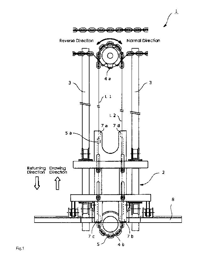
Fig. 1 is a top view of a sludge treatment apparatus.
Fig. 2 is a top view of a chain.
Fig. 3 is a side view of the chain.
Fig. 4 is a side view of a sludge drawing tool.
Fig. 5 is a schematic top view of a slide portion.
Fig. 6 is an explanatory view of an operation for
moving a scraper upward and downward.
Fig. 7 is an explanatory view of a forward movement
of the sludge drawing tool caused by a rotation of a
driving wheel in a forward direction.
Fig. 8 is an explanatory view illustrating how the
6
CA 03072147 2020-02-05
sludge drawing tool is reversed in the middle of a movement.
Fig. 9 is a front view of a wheel with stopper.
Fig. 10 is a side view of the wheel with a stopper.
Fig. 11 is an explanatory diagram of an operation of
the stopper.
Fig. 12 is a front view of a wheel with stopper
according to a modification.
Fig. 13 is an explanatory view of a conventional
technique.
Description of Embodiments
[0011]
Fig. 1 is a top view of a sludge treatment apparatus
according to the present embodiment. The sludge treatment
apparatus 1 is arranged on the bottom of a tank containing
treatment target water, for drawing up and discharging the
sludge settled in the tank using a scraper 8. The sludge
treatment apparatus 1 mainly includes a sludge drawing tool
2 that is a moving body having the scraper 8 for drawing up
the sludge, rails 3, a pair of wheels 4a and 4b, and a
chain 5 serving as a power transmission member. The
present embodiment features the following three points.
The first point is that the sludge drawing tool 2 makes
forward movement between the pair of wheels 4a and 4b, that
is, moves alternately in a drawing direction and a
7
CA 03072147 2020-02-05
returning direction, simply by continuously rotating the
driving wheel 4a in one direction. The second point is
that the scraper 8 that is a component of the sludge
drawing tool 2 moves upward and downward in accordance with
the traveling direction of the sludge drawing tool 2.
Specifically, the scraper 8 moves downward in response to
the movement in the drawing direction for drawing in the
sludge, and moves upward in response to the movement in the
returning direction. The third point is that the movement
direction of the sludge drawing tool 2 can be freely
switched, even during the movement of the sludge drawing
tool 2. Thus, reversing to the returning direction can be
implemented in the middle of the movement in the drawing
direction, and reversing to the drawing direction can be
implemented in the middle of the movement in the returning
direction.
[0012]
The two rails 3 are arranged in parallel to each
other on the bottom of the tank. At one end of the rails 3,
that is, in an end portion in the drawing direction, the
bottom of the tank is depressed to be formed into a pit for
discharging the sludge. The pair of wheels 4a and 4b are
provided at both ends of the rails 3. In the present
embodiment, the driving wheel 4a is disposed at the end in
the drawing direction, and the driven wheel 4b is disposed
8
CA 03072147 2020-02-05
at the end in the returning direction. It is to be noted
that, driving force can also be transmitted to the sludge
drawing tool 2 with the wheels 4a and 4b arranged
oppositely, that is, with the driving wheel 4a disposed at
the end in the returning direction.
[0013]
The chain 5 is an endless power transmission member
that is wound around the pair of wheels 4a and 4b. The
chain 5 includes two semicircular arc-shaped curved lines
extending along the outer circumferences of the respective
wheels 4a and 4b and two straight lines Li and L2 extending
between the wheels 4a and 4b. Note that a belt or the like
may be used instead of the chain 5 as a member for
transmitting driving force to the sludge drawing tool 2.
[0014]
The driving force from a driving source such as a
motor (not illustrated) is transmitted to the driving wheel
4a via a chain provided separately from the chain 5, to
rotate the driving wheel 4a. When the driving wheel 4a
rotates, the chain 5 wound around the wheels 4a and 4b
moves, so that the driving force is transmitted to the
sludge drawing tool 2. The driving wheel 4a rotate in any
of the normal direction and the reverse direction, by
switching the rotation direction of the driving source.
[0015]
9
CA 03072147 2020-02-05
Power transmission from the driving source to the
driving wheel 4a via the chain provides an advantage that
the number of sludge treatment apparatuses 1 arranged in
parallel can be adjusted flexibly and inexpensively.
However, if such an effect needs not to be taken into
consideration, for example, the driving wheel 4a may be
directly attached to a rotation shaft of the driving source
arranged above the driving wheel 4a.
[0016]
Fig. 2 is a top view of the chain 5, and Fig. 3 is a
side view thereof. A pulling portion 5a having a pin-like
shape protruding in a predetermined direction is attached
to a part of the chain 5 by welding or the like. The
pulling portion 5a is provided so as to protrude upward in
the top view of Fig. 1, but may be provided so as to
protrude laterally outward in the figure. The pulling
portion 5a may have any shape as long as engagement
portions 7a to 7d described later can be free engage
therewith and disengaged therefrom. An example such a
shape includes a hook shape. The pulling portion 5a can
circumferentially move along the chain 5 as the driving
wheel 4a rotates.
[0017]
The sludge drawing tool 2 is arranged on the two
rails 3, and can freely move forward in the drawing
CA 03072147 2020-02-05
direction and in the returning direction between the pair
of wheels 4a and 4b. As illustrated in Fig. 1, the sludge
drawing tool 2 is provided with the four engagement
portions 7a to 7d, and is pulled in the drawing direction
and in the returning direction with the pulling portion 5a,
circumferentially moving along the chain 5, coming into
contact with any of the engagement portions 7a to 7d.
[0018]
Fig. 4 is a side view of the sludge drawing tool 2.
The sludge drawing tool 2 mainly includes a carriage 6, a
slide portion 7, and the scraper 8. The carriage 6
includes a plurality of wheels 6a for moving on the two
rails 3, to be movable on the rail 3. Furthermore, the
carriage 6 has a lower surface provided with a protruding
portion 6b protruding downward.
[0019]
The slide portion 7 is slidably attached to the
lower side of the carriage 6. The slide portion 7 has an
upper surface provided with a depression extending for a
predetermined length, along the movement direction of the
sludge drawing tool 2, to serve as a guide groove 7e. The
protruding portion 6b on the carriage 6 side is inserted in
the guide groove 7e. As a result, the movable (slidable)
range of the slide portion 7 with respect to the carriage 6
is limited to a range defined by the guide groove 7e.
11
CA 03072147 2020-02-05
[0020]
Fig. 5 is a schematic top view of the slide portion
7. The chain 5 is provided through the inside of the slide
portion 7 having both side surfaces provided with the
above-described four engagement portions 7a to 7d. These
engagement portions 7a to 7d protrude toward the chain 5,
and are shaped to enable the pulling portion 5a,
circumferentially moving along the chain 5, to be engaged
therewith and to be disengaged therefrom. The engagement
portions 7a and 7c are provided at different positions near
the straight line Li, and the engagement portions 7b and 7d
are provided at different positions near the straight line
L2. The engagement portions 7a and 7d are provided at
opposite positions, and have shapes that are line-symmetric
about an axis of symmetry P connecting the center axes of
the pair of wheels 4a and 4b. Furthermore, the engagement
portions 7b and 7c are provided at opposite positions and
have shapes that are line-symmetric about the axis of
symmetry P.
[0021]
When the driving wheel 4a rotates in the normal
direction, the slide portion 7 (sludge drawing tool 2) is
pulled by means of the engagement portions 7a and 7b.
Specifically, when the driving wheel 4a rotates in the
normal direction, the engagement portion 7a comes into
12
CA 03072147 2020-02-05
contact with the pulling portion 5a moving in the drawing
direction on the straight line Ll, to make the slide
portion 7 move in the drawing direction. The engagement
portion 7b comes into contact with the pulling portion 5a
moving on the straight line L2 in the returning direction,
to make the slide portion 7 move in the returning direction.
[0022]
When the driving wheel 4a rotates in the reverse
direction, the slide portion 7 (sludge drawing tool 2) is
pulled by means of the engagement portions 7c and 7d.
Specifically, when the driving wheel 4a rotates in the
reverse direction, the engagement portion 7c comes into
contact with the pulling portion 5a moving in the returning
direction on the straight line Li, to make the slide
portion 7 move in the returning direction. The engagement
portion 7d comes into contact with the pulling portion 5a
moving on the straight line L2 in the drawing direction, to
make the slide portion 7 move in the drawing direction.
[0023]
The scraper 8 extends substantially orthogonally to
the rails 3, and has a shape to draw in the sludge settled
in the tank. The scraper 8 is attached to the carriage 6
via a rotation shaft 9, as illustrated in Fig. 4.
Furthermore, a link mechanism 10 is provided between the
slide portion 7 and the scraper 8 to couple these elements
13
CA 03072147 2020-02-05
to each other. The link mechanism 10 rotates the scraper 8
in accordance with the sliding of the slide portion 7 with
respect to the carriage 6. Thus, the scraper 8 moves
upward and downward. Specifically, as illustrated in Fig.
6, in a state where the slide portion 7 is pulled out
toward the right side with respect to the carriage 6 (a
state indicated by a broken line), the scraper 8 is lowered.
As the slide portion 7 in this state is pushed toward the
left side, the scraper 8 gradually rises. When the slide
portion 7 is completely pushed in, the scraper 8 is
completely raised. The scraper 8 is gradually lowered as
the slide portion 7 is pulled out toward the right side
after being pushed toward the left side relative to the
carriage 6 to completely raise the scraper 8. Then, when
the slide portion 7 is completely pulled out, the scraper 8
is completely lowered.
[0024]
Next, an operation of the sludge drawing tool 2 will
be described. Fig. 7 is an explanatory view of a forward
movement of the sludge drawing tool 2 caused by the forward
rotation of the driving wheel 4a. For example, the pulling
portion 5a moving on the straight line Li of the chain 5 in
the drawing direction comes into contact with the
engagement portion 7a. As a result, the slide portion 7
(sludge drawing tool 2) moves in the drawing direction
14
CA 03072147 2020-02-05
until the pulling portion 5a reaches the end of the
straight line Li, with the lowered state (a state for
scraping the sludge) of the scraper 8 maintained. Upon
reaching the end of the straight line Li, the pulling
portion Sa starts to move on the curved line along the
outer circumference of the driving wheel 4a, to gradually
move away from the engagement portion 7a. Then, when the
pulling portion 5a reaches a position P1 to be disengaged
from the engagement portion 7a, the slide portion 7 (sludge
drawing tool 2) stops while maintaining the lowered state
(end position).
[0025]
After moving on the curved line, the pulling portion
5a enters the straight line L2. In this process, the
entrance of the pulling portion 5a will not be hindered by
the engagement portion 7d at the end position where the
slide portion 7 has stopped, because the engagement
portions 7a and 7d have the same protruding height. Then,
the pulling portion 5a reaches a position P2 on the
straight line L2 to come into contact with the engagement
portion 7b. Thus, the slide portion 7 starts to move in
the returning direction that is opposite to the drawing
direction. The resistance against the sliding of the slide
portion 7 on the carriage 6 is smaller than the resistance
against the movement the carriage 6 on the rail 3. Thus,
CA 03072147 2020-02-05
the movement of the pulling portion 5a after passing
through the position P2 results in the slide portion 7
sliding with respect to the carriage 6. As a result, the
scraper 8 that has been lowered starts to rise. Then, when
the pulling portion 5a moves to the end of the movable
range defined by the guide groove 7e, the scraper 8 is
completely raised, and the carriage 6 and the slide portion
7 integrally moves in the returning direction as the sludge
drawing tool 2.
[0026]
The same applies to the operation on the driven
wheel 4b side. Specifically, when the pulling portion 5a
is disengaged from the engagement portion 7b, the sludge
drawing tool 2 stops in the raised state. Then, the
scraper 8 starts to be lowered when the pulling portion Sa
comes into contact with the engagement portion 7a. When
the scraper 8 is completely lowered, the sludge drawing
tool 2 moves in the drawing direction.
[0027]
The reverse rotation of the driving wheel 4a results
in an operation that is basically the same as the operation
described above. However, in this case, the forward
movement of the sludge drawing tool 2 involving upward and
downward movement of the scraper 8 occurs with the pulling
portion 5a alternately coming into contact with the
16
CA 03072147 2020-02-05
engagement portions 7c and 7d instead of the engagement
portions 7a and 7b.
[0028]
In this manner, the forward movement of the sludge
drawing tool 2 involving the upward and downward movement
of the scraper 8 can be automatically implemented simply by
rotating the driving wheel 4a in a predetermined direction.
This is advantageous in that no sensor needs to be provided
for detecting the end position of the sludge drawing tool 2
and that the driving wheel 4a needs not to be alternately
rotated in the forward and the reverse directions.
[0029]
Fig. 8 is an explanatory view illustrating how the
sludge drawing tool 2 is reversed in the middle of a
movement. For example, the pulling portion 5a moving on
the straight line Li of the chain 5 in the drawing
direction comes into contact with the engagement portion 7a.
As a result, the slide portion 7 (sludge drawing tool 2)
moves in the drawing direction with the lowered state of
the scraper 8 maintained. If the driving wheel 4a is
reversed during this movement, the pulling portion 5a on
the straight line Li starts to move in the opposite
direction. As a result, the pulling portion 5a is
disengaged from the engagement portion 7a, and the sludge
drawing tool 2 stops with the lowered state maintained.
17
CA 03072147 2020-02-05
[0030]
The pulling portion 5a moving on the straight line
Li reaches a position P3 to come into contact with the
engagement portion 7c arranged on the same straight line Ll.
As a result, the scraper 8 starts to rise. When the
scraper 8 is completely raised, the sludge drawing tool 2
moves in the returning direction.
[0031]
The operation described above occurs as a result of
making the driving wheel 4a that has been rotating in the
forward direction rotate in the reverse direction. An
operation as a result of making the driving wheel 4a that
has been rotating in the reverse direction rotate in the
forward direction is basically the same. However, in this
case, the reverse movement of the sludge drawing tool 2
involving upward and downward movement of the scraper 8
occurs with the pulling portion 5a coming into contact with
the engagement portions 7c and 7d one by one, instead of
the engagement portions 7a and 7b.
[0032]
A stopper for achieving temporary braking of the
carriage 6 may be provided to ensure that the carriage 6
does not move during the raising and lowering processes of
the scraper 8. Fig. 9 is a front view of a wheel with a
stopper as an example, and Fig. 10 is a side view thereof.
18
CA 03072147 2020-02-05
This stopper 11 is made of metal and has a pair of arms ha
and lib and a contact portion llc. The pair of arms ha
and llb are eccentrically and rotatably mounted on the
rotation shaft of the wheel 6a. The contact portion 11c is
integrally provided to the tips of these arms ha and 11b,
to come into contact with the rails 3 for generating
frictional force (braking force). The contact portion 11c
protrudes beyond the outer circumference of the wheel 6a,
and has a curved outer circumference surface processed
(knurled) to have recesses and protrusions for applying
strong braking force to the carriage 6.
[0033]
Fig. 11 is a diagram illustrating an operation of
the stopper 11. As illustrated in a part (a) of the figure,
the stopper 11 is positioned on the travelling direction
side (obliquely forward) at a timing when the sludge
drawing tool 2 is reversed. In this state, the carriage 6
receives a predetermined amount of braking force due to the
frictional force between the stopper 11 and the rails 3
based on the weight of the stopper 11 and the effect of the
stopper 11, positioned obliquely forward, being stuck to
the rails 3. As a result, the carriage 6 stops without
being dragged by the slide portion 7, meaning that only the
slide portion 7 slides until reaching the end of the
movable range.
19
CA 03072147 2020-02-05
[0034]
Then, when the slide portion 7 sliding on the
carriage 6 reaches the end of the movable range, the force
transmitted to the slide portion 7 via the chain 5 directly
acts on the carriage 6. As a result, the wheel 6a moves
over the stopper 11 as illustrated in a part (b) of the
figure. Thus, the stopper 11 is located on the opposite
side (obliquely rearward) in the traveling direction as
illustrated in a part (c) of the figure. Thus, the braking
force to the carriage 6 is released, whereby the carriage 6
and the slide portion 7 integrally moves in the traveling
direction.
[0035]
Fig. 12 is a front view of a wheel with a stopper
according to a modification. This stopper 11' has one arm
ha with a distal end surface provided with the above-
mentioned contact portion llc. In this case, the contact
portion llc has a smaller are than in the configuration of
Fig. 9, but can guarantee a certain amount of braking force.
[0036]
As described above, according to the present
embodiment, the sludge drawing tool 2 moves forward with
the pulling portion 5a alternately coming into contact with
the engagement portions 7a and 7b when the driving wheel 4a
rotates in the forward direction, and moves forward with
CA 03072147 2020-02-05
the pulling portion 5a alternately coming into contact with
the engagement portions 7c and 7d when the driving wheel 5a
rotates in the reverse direction. To reverse the traveling
direction in the middle of the movement of the sludge
drawing tool 2, the driving wheel 4a is reversed. As a
result, the pulling portion 5a that has been in contact
with one engagement portion (7a for example) moves on the
straight line and comes into contact with another
engagement portion (7c for example) arranged on same the
straight line, so that the traveling direction of the
sludge drawing tool 2 is reversed. As a result, the
traveling direction can be reversed at any desired position
during the movement of the sludge drawing tool 2. This is
advantageous in terms of improving the maintainability of
the sludge treatment apparatus 1 is improved and making an
unexpected situation easier to be handled.
[0037]
The sludge drawing tool 2 according to the present
embodiment is configured as follows. Specifically, the
slide portion 7 slidable with respect to the carriage 6 is
provided for causing the pulling of the sludge drawing tool
2 with the slide portion 7 as starting point. The link
mechanism 10 is provided to couple the slide portion 7 and
the scraper 8 to each other. Thus, automatic upward and
downward movement of the scraper 8 linked with the forward
21
CA 03072147 2020-02-05
movement of the sludge drawing tool 2 can be implemented
using the power transmitted via the chain 5. The upward
and downward movement can be implemented with a mechanical
mechanism without providing the sludge drawing tool 2 with
a driving source (such as a motor). This is advantageous
in that the sludge treatment apparatus I can have a higher
durability and maintainability.
[0038]
The sludge drawing tool 2 according to the present
embodiment is further configured as follows. Specifically,
the slide portion 7 is provided on the lower side of the
carriage 6, and the chain 5 is provided through the inside
of the slide portion 7. As a result, the sludge drawing
tool 2 can have a low height, so as to be effectively
prevented from interfering with other members in the tank
(such as an inclined plate enabling swift sinking of the
sludge in the water).
[0039]
In the embodiment described above, the sludge
drawing tool 2 is provided with the raising and lowering
mechanism including the slide portion 7 and the link
mechanism 10 so that the scraper 8 can be raised and
lowered with the power supplied from the chain 5. Such a
raising and lowering mechanism needs not to be provided in
cases such as a case where the power is externally supplied
22
CA 03072147 2020-02-05
from a system different from the chain 5 or a case where
the sludge drawing tool 2 is provided with a driving source
for the upward and downward movement.
Reference Signs List
[0040]
1 Sludge treatment apparatus
2 Sludge drawing tool
3 Rail
4a Driving wheel
4b Driven wheel
Chain
5a Pulling portion
6 Carriage
6a Wheel
6b Protruding portion
7 Slide portion
7a to 7d Engagement portion
7e Guide groove
8 Scraper
9 Rotation shaft
Link mechanism
11, 11' Stopper
ha, llb Arm
11c Contact portion
23
CA 03072147 2020-02-05
FIG. 1
REVERSE ROTATION
NORMAL ROTATION
RETURNING DIRECTION
DRAWING DIRECTION
FIG. 5
RETURNING DIRECTION
DRAWING DIRECTION
REVERSE ROTATION
NORMAL ROTATION
FIG. 7
DRAWING DIRECTION
NORMAL ROTATION
29