Note : Les descriptions sont présentées dans la langue officielle dans laquelle elles ont été soumises.
CA 03072520 2020-02-07
WO 2019/074696 PCT/US2018/053412
1
EASY START CANNULATED BONE SCREW
CROSS-REFERENCE TO RELATED APPLICATIONS
[0001] This application claims priority to U.S. Provisional Patent
Application Serial No.
62/569,770, filed on October 9, 2017 and entitled "Easy Start Cannulated Bone
Screw," and
U.S. Provisional Patent Application Serial No. 62/599,228, filed on December
15, 2017 and
entitled "Easy Start Cannulated Bone Screw."
BACKGROUND OF THE INVENTION
1. Field of the Invention
[0002] The present disclosure is directed generally to a surgical fixation
device and,
more particularly, to a cannulated screw for fixation into bone or soft
tissue.
2. Description of Related Art
[0003] In orthopedic surgeries, screws are often used to secure and fix
biological
material or another object, such as an implant, in a desired position relative
to a bone. For
example, screws are used to attach a bone block to an existing bone or to
secure soft tissue to
a bone or soft tissue. The initial threading of the screw into the bone or a
bone block can be
difficult. Therefore, in some procedures, a pilot hole is required to aid in
alignment of the
screw. As well understood in the surgical field, the pilot hole is smaller in
depth and diameter
than the screw to provide a guide for the screw, while still being narrow
enough to allow
enough of the threads of the screw to penetrate the boney interference site. A
mallet may also
be used to hammer the screw deep enough for the threads to penetrate the boney
interference
site.
[0004] Drilling a pilot hole requires additional surgical time and
additional surgical
instruments. While using a mallet to hammer the screw into the bone may be
less time
consuming and require less instrumentation, it is less precise. Hammering the
screw into the
bone carries a greater risk that the screw will become misaligned with the
desired fixation
location. Therefore, there is a need for a surgical screw that does not
require the use of a pilot
hole or a mallet, while maintaining sturdy and reliable fixation within the
bone.
SUMMARY OF THE INVENTION
[0005] The present invention is directed to a surgical screw. The surgical
screw
comprises features for reducing the torque required to start or introduce the
screw into the
anatomy. According to one aspect, the surgical screw includes a cannulated
body having a
proximal end and a distal end. The distal end of the cannulated body can have
a tapered tip,
and a plurality of threads which can extend around the exterior of the
cannulated body from a
CA 03072520 2020-02-07
WO 2019/074696 PCT/US2018/053412
2
position at the very distal end, a position adjacent to the distal end, or a
position proximal to
the distal end to a position at the very proximal end, a position adjacent to
the distal end, or a
position distal of the proximal end. An introducer extends distally from the
tapered tip and
has a diameter (which can be constant or variable) which is less than a
diameter of the
tapered tip. The surgical screw is cannulated such that a channel extends
through the body
from the proximal end to the distal end.
[0006] According to another aspect, the surgical screw includes a
cannulated body
having a proximal end and a distal end, which has a tapered tip. A plurality
of threads extend
around the exterior of the cannulated body (from positions as described
above). The plurality
of threads include a primary thread and a secondary thread. A lead of the
primary thread is
greater than a pitch of the plurality of threads. An introducer extends
distally from the tapered
tip. The surgical screw is cannulated such that a channel extends through the
body from the
proximal end to the distal end.
[0007] It should be appreciated that all combinations of the foregoing
concepts and
additional concepts discussed in greater detail below (provided such concepts
are not
mutually inconsistent) are contemplated as being part of the inventive subject
matter
disclosed herein. In particular, all combinations of claimed subject matter
appearing at the
end of this disclosure are contemplated as being part of the inventive subject
matter disclosed
herein. It should also be appreciated that terminology explicitly employed
herein that also
may appear in any disclosure incorporated by reference should be accorded a
meaning most
consistent with the particular concepts disclosed herein.
[0008] These and other aspects of the invention will be apparent from and
elucidated
with reference to the embodiment(s) described hereinafter.
BRIEF DESCRIPTION OF THE DRAWINGS
[0009] One or more aspects of the present invention are particularly
pointed out and
distinctly claimed as examples in the claims at the conclusion of the
specification. The
foregoing and other objects, features, and advantages of the invention are
apparent from the
following description taken in conjunction with the accompanying drawings in
which:
[0010] FIG. 1 is a proximal perspective view schematic representation of a
surgical
screw, according to an embodiment;
[0011] FIG. 2 is a distal perspective view schematic representation of a
surgical screw,
according to an embodiment;
CA 03072520 2020-02-07
WO 2019/074696 PCT/US2018/053412
3
[0012] FIG. 3 is side view schematic representation of a surgical screw,
according to an
embodiment;
[0013] FIG. 4 is a perspective view schematic representation of a surgical
screw,
according to an alternative embodiment;
[0014] FIG. 5 is a side view schematic representation of a surgical screw,
according to an
alternative embodiment;
[0015] FIG. 6 is a distal perspective view schematic representation of a
surgical screw,
according to an alternative embodiment;
[0016] FIG. 7 is a distal end view schematic representation of a surgical
screw,
according to an alternative embodiment;
[0017] FIG. 8 is a distal perspective view schematic representation of a
surgical screw,
according to an embodiment;
[0018] FIG. 9 is a side view schematic representation of a surgical screw,
according to an
alternative embodiment; and
[0019] FIG. 10 is a side view schematic representation of a surgical screw,
according to
another embodiment;
[0020] FIG. 11 is a side view schematic representation of a surgical screw,
according to
yet another embodiment;
[0021] FIG. 12 is a close-up view schematic representation of an exemplary
embodiment
of a surgical screw with a single start; and
[0022] FIG. 13 is a close-up view schematic representation of an exemplary
embodiment
of a surgical screw with a double start.
DETAILED DESCRIPTION OF THE INVENTION
[0023] Aspects of the present invention and certain features, advantages,
and details
thereof, are explained more fully below with reference to the non-limiting
examples
illustrated in the accompanying drawings. Descriptions of well-known
structures are omitted
so as not to unnecessarily obscure the invention in detail. It should be
understood, however,
that the detailed description and the specific non-limiting examples, while
indicating aspects
of the invention, are given by way of illustration only, and are not by way of
limitation.
Various substitutions, modifications, additions, and/or arrangements, within
the spirit and/or
scope of the underlying inventive concepts will be apparent to those skilled
in the art from
this disclosure.
CA 03072520 2020-02-07
WO 2019/074696 PCT/US2018/053412
4
[0024] Referring now to the figures, wherein like reference numerals refer
to like parts
throughout, FIG. 1 shows a proximal perspective view schematic representation
of a surgical
screw 100, according to an embodiment. The surgical screw 100 comprises a body
102
extending between a proximal end 104 and a distal end 106. The surgical screw
100 can be
composed of any suitable biocompatible material, such as titanium or
magnesium, and can be
manufactured according to common manufacturing methods, such as machining (as
should be
understood by a person of ordinary skill in the art in conjunction with a
review of this
disclosure). The surgical screw 100 may also be composed of bio-composite
material and
manufactured via injection molding (as should be understood by a person of
ordinary skill in
the art in conjunction with a review of this disclosure).
[0025] As shown in FIG. 1, the body 102 comprises a feature 108 at the
proximal end
104 that allows the surgical screw 100 to be torqued. Specifically, the
feature 108 is on an
outer surface 110 of the proximal end 104. For example, the feature 108 can be
that of any
conventional screw head and non-conventional geometries as well (e.g., Tr-Lobe
driver
geometry). In the depicted embodiment, the feature 108 has a hexagonal cross-
section. As
shown in FIG. 1, the surgical screw 100 is cannulated such that a channel 112
extends from
the feature 108 at the outer surface 110 of the proximal end 104 through the
body 102 to the
distal end 106.
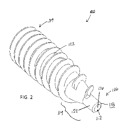
[0026] Turning now to FIG. 2, there is shown a distal perspective view
schematic
representation of the surgical screw 100, according to an embodiment. In the
depicted
embodiment, the body 102 of the surgical screw 100 comprises a tip 114 at the
distal end
106. In FIG. 2, the tip 114 is a tapered region (at least partially tapered,
can be tapered all the
way to the very distal end, and can include a constant, variable - increasing
or decreasing
taper, or more than one taper (which may be separated with a section with no
taper) with the
same or different taper value) such that the body 102 is tapered toward the
distal end 106. As
described above, the surgical screw 100 is cannulated. FIG. 2 shows the
channel 112
extending through the body 102 of the surgical screw 100 to the tip 114 at the
distal end 106.
Specifically, the channel 112 extends from the feature 108 at the proximal end
104 to an
opening 116 on an outer surface 118 of the tip 114.
[0027] Still referring to FIG. 2, the surgical screw 100 comprises an
introducer 120 at the
tip 114. In the depicted embodiment, the introducer 120 is an elongated
extension from the
tip 114. In the depicted embodiment, the introducer 120 is a narrow cylinder
extending from
the tip 114 at the distal end 106. As shown, the introducer 120 is also
cannulated such that the
CA 03072520 2020-02-07
WO 2019/074696 PCT/US2018/053412
introducer 120 has the outer surface 118 with the opening 116 to the channel
112 extending
through the body 102. The introducer 120 allows for easier insertion of the
surgical screw
100 because the introducer 120 can be used to align the surgical screw 100 at
the desired
bone hole location.
[0028] Referring now to FIG. 3, there is shown a side view schematic
representation of the
surgical screw 100, according to an embodiment. As shown in FIG. 3, the
surgical screw 100
comprises a plurality of threads 122 along the length of the body 102. As with
all
conventional screws, adjacent threads 122 have a pitch p and root diameter d.
However, the
pitch p and therefore, the root diameter d of the depicted embodiment of the
surgical screw
100 can be variable/non-constant (alternatively, the pitch can be variable and
the root
diameter can be constant or vice versa, and the pitch and/or the root diameter
can be variable
for a certain length of the body and constant for another length of the body).
In other words,
the threads 122 of the surgical screw 100 are not evenly spaced. In one
embodiment, the pitch
p increases from the proximal end 104 to the distal end 106, while the root
diameter d
increases from the distal end 106 to the proximal end 104. For example, as
shown in FIG. 3,
the pitch p1 at the distal end 106 is larger than the pitch p2 at the proximal
end 104, and the
root diameter at the distal end 106 is smaller than the root diameter at the
proximal end 104.
[0029] Still referring to FIG. 3, the threads 122 of the surgical screw 100
are dual start
threads. Dual start threads are two threads opposed at 180 degrees. As shown
in FIG. 3, the
surgical screw 100 comprises a staggered start 124. In other words, a
secondary thread 128
begins 180 degrees later than a primary thread 126. As shown in FIG. 13, the
primary thread
122A has a lead L, which is greater than the pitch p of the threads 122 (122A,
122B) when
the surgical screw 100 has a dual start or staggered start 124. The surgical
screw 100 may
also have a triple start or any additional multiple start (as should be
understood by a person of
ordinary skill in the art in conjunction with a review of this disclosure, not
shown) or a single
start (FIG. 12) where the lead L and the pitch p are equal. In an embodiment,
as shown in
FIG. 3, the primary thread 126 has a reduced surface area A. The reduced
surface area A
reduces resistance and lowers torque during initial engagement with the bone.
[0030] Turning now to FIGs. 4-11, there are shown various views schematic
representations of surgical screw 100 according to alternative embodiments.
First, in FIG. 4,
there is shown a perspective view schematic representation of a surgical screw
100, according
to an alternative embodiment. As with the surgical screw 100 in FIGs. 1-3, the
surgical screw
100 in FIG. 4 comprises a body 102 extending between a proximal end 104 and a
distal end
CA 03072520 2020-02-07
WO 2019/074696 PCT/US2018/053412
6
106 with a feature 108 on an outer surface 110 at the proximal end 104, which
allows the
surgical screw 100 to be torqued. As shown in FIG. 4, the surgical screw 100
is cannulated
such that a channel 112 extends from the feature 108 at the outer surface 110
of the proximal
end 104 through the body 102 to the distal end 106. As with the surgical screw
100 of FIGs.
1-3, the surgical screw 100 shown in FIGs. 4-11 can be composed of any
suitable
biocompatible material, such as titanium or magnesium, or bio-composite
material, and can
be manufactured according to common manufacturing methods, such as machining
or
injection molding, for example.
[0031] FIG. 5 shows a side view schematic representation of a surgical
screw 100,
according to an alternative embodiment. The surgical screw 100 shown in FIG. 5
has threads
122 extending along the body 102 of the screw 100. Adjacent threads 122 in the
depicted
embodiment have a constant (i.e., equal) pitch p. However, the surgical screw
100 may also
have threads 122 with a variable pitch p1, p2, as shown in the embodiment in
FIG. 3. The
embodiment of the surgical screw 100 in FIG. 5 also has threads 122 with a
root diameter d
that is tapered from the proximal end 104 to the distal end 106. Specifically,
the root diameter
d decreases from the proximal end 104 to the distal end 106 (which can be a
constant
decrease in diameter in some embodiments, and a non-constant decrease in
diameter in other
embodiments).
[0032] Still referring to FIG. 5, the embodiment of the surgical screw 100
also includes a
dual start thread (i.e., staggered start) 124. As stated above, the dual start
thread 124 includes
a primary thread 126, which is 180 degrees opposed from a secondary thread 128
such that
the secondary thread 128 starts 180 degrees later (i.e., around the exterior
of the body 102)
than the primary thread 126. However, in other embodiments, the secondary
thread 128 can
start anywhere from a little as 5 degrees to as most as 360 degrees later than
the primary
thread 126. The primary thread 126 and secondary thread 128 have reduced
surface areas Al,
A2 to reduce resistance and lower torque during initial engagement with the
bone.
[0033] Turning now to FIGs. 6-7, there are shown distal end and distal
perspective views
schematic representations of a surgical screw 100, according to an alternative
embodiment. In
the depicted embodiment of the surgical screw 100, the primary thread 126 and
the secondary
thread 128 are chamfered. The chamfering removes a leading edge from the
primary and
secondary threads, further reducing the surface area Al, A2 thereof. As shown
in FIG. 6, the
chamfering creates a first sharp edge 130 on the primary thread 126 and a
second sharp edge
132 on the secondary thread 128. The sharp edges 130, 132 allow for better
engagement
CA 03072520 2020-02-07
WO 2019/074696 PCT/US2018/053412
7
between the surgical screw 100 and bone. In the depicted embodiment, the
distal portion 134
of the primary thread 126 is configured such that the surface area Al of the
primary thread
126 is further reduced as compared to the surface area A2 of the secondary
thread 128. In
additional embodiments, a radius is used in place of the chamfer when the
surgical screw 100
is used for engagement with soft tissue as opposed to bone.
[0034] Referring now to FIG. 8, there is shown a distal perspective view
schematic
representation of a surgical screw 100, according to an embodiment. In the
depicted
embodiment, the surgical screw 100 includes a notching feature 136 at the
distal end 106. In
one embodiment, as shown in FIG. 8, the notching feature 136 extends from the
introducer
120 at the distal end 106 of the surgical screw 100. In the depicted
embodiment, the notching
feature 136 is a notch that extends approximately tangentially from the
introducer 120. The
notching feature 136 can be malleted into the bone when the bone is hard. For
example, a
surgeon will align the introducer 120 at the desired bone hole location and
mallet the
proximal end 104 of the surgical screw 100 such that the introducer 120 and
notching feature
136 engage the bone. In another embodiment, the notching feature 136 is used
to find gaps
between a primary bone and a graft when the surgical screw 100 is rotated.
When the
notching feature 136 finds a gap, it directs the primary thread 126 to the
desired area and the
surgical screw 100 can be rotated and installed without the need for
malleting.
[0035] Turning now to FIGs. 9-10, there are shown side views schematic
representations
of a surgical screw 100, according to additional embodiments. In the
embodiment shown in
FIGs. 9-10, the opening 116 to the channel 112 at the distal end 106
(introducer 120) of the
surgical screw 100 is solid or otherwise replaced with a solid feature 138.
The solid feature
138 may be rounded, as shown in FIG. 9, or the solid feature 138 may have any
other suitable
geometry. For example, the solid feature 138 may be a drill tip 140, as shown
in FIG. 10. In
the embodiments shown in FIGs. 9-10, the solid feature 138 is not cannulated.
However, in
alternative embodiments, the cannulation may also be completely removed (as in
FIGs. 9-10)
or only partially removed. In other words, the solid feature 138 can be either
completely solid
or only partially solid.
[0036] Referring now to FIG. 11, there is shown a side view schematic
representation of
a surgical screw 100, according to yet another embodiment. In the depicted
embodiment, the
surgical screw 100 comprises one or more exterior markings 142 along the body
102 between
the proximal end 104 and the distal end 106. The exterior markings 142 of the
surgical screw
100 in FIG. 11 are depth indicator markings 142. The depth indicator markings
142 are
CA 03072520 2020-02-07
WO 2019/074696 PCT/US2018/053412
8
visible to a surgeon (or other user) during rotation and installation of the
surgical screw 100.
The depth indicator markings 142 allow the surgeon to determine the depth of
the surgical
screw 100 within the bone or soft tissue. In the depicted embodiment, the
depth indicator
markings 142 are circumferential markings extending around the exterior of the
surgical
screw 100. However, the depth indicator markings 142 can be placed anywhere
along the
exterior of the surgical screw 100 such that they are visible to the surgeon
(or other user). As
shown in FIG. 11, the depth indicator markings 142 can include multiple
markings 142
spaced at equidistant intervals (e.g., 5 mm), a single depth marking, or
multiple markings
spaced at irregular intervals, as desired, and can be made from or coated with
radiographic
material.
[0037] All definitions, as defined and used herein, should be understood to
control over
dictionary definitions, definitions in documents incorporated by reference,
and/or ordinary
meanings of the defined terms.
[0038] While various embodiments have been described and illustrated
herein, those of
ordinary skill in the art will readily envision a variety of other means
and/or structures for
performing the function and/or obtaining the results and/or one or more of the
advantages
described herein, and each of such variations and/or modifications is deemed
to be within the
scope of the embodiments described herein. More generally, those skilled in
the art will
readily appreciate that all parameters, dimensions, materials, and
configurations described
herein are meant to be exemplary and that the actual parameters, dimensions,
materials,
and/or configurations will depend upon the specific application or
applications for which the
teachings is/are used. Those skilled in the art will recognize, or be able to
ascertain using no
more than routine experimentation, many equivalents to the specific
embodiments described
herein. It is, therefore, to be understood that the foregoing embodiments are
presented by
way of example only and that, within the scope of the appended claims and
equivalents
thereto, embodiments may be practiced otherwise than as specifically described
and claimed.
Embodiments of the present disclosure are directed to each individual feature,
system, article,
material, kit, and/or method described herein. In addition, any combination of
two or more
such features, systems, articles, materials, kits, and/or methods, if such
features, systems,
articles, materials, kits, and/or methods are not mutually inconsistent, is
included within the
scope of the present disclosure.
[0039] The terminology used herein is for the purpose of describing
particular
embodiments only and is not intended to be limiting of the invention. As used
herein, the
CA 03072520 2020-02-07
WO 2019/074696 PCT/US2018/053412
9
singular forms "a", "an" and "the" are intended to include the plural forms as
well, unless the
context clearly indicates otherwise. It will be further understood that the
terms "comprise"
(and any form of comprise, such as "comprises" and "comprising"), "have" (and
any form of
have, such as, "has" and "having"), "include" (and any form of include, such
as "includes"
and "including"), and "contain" (any form of contain, such as "contains" and
"containing")
are open-ended linking verbs. As a result, a method or device that
"comprises", "has",
"includes" or "contains" one or more steps or elements. Likewise, a step of
method or an
element of a device that "comprises", "has", "includes" or "contains" one or
more features
possesses those one or more features, but is not limited to possessing only
those one or more
features. Furthermore, a device or structure that is configured in a certain
way is configured
in at least that way, but may also be configured in ways that are not listed.
[0040] The corresponding structures, materials, acts and equivalents of all
means or step
plus function elements in the claims below, if any, are intended to include
any structure,
material or act for performing the function in combination with other claimed
elements as
specifically claimed. The description of the present invention has been
presented for
purposes of illustration and description, but is not intended to be exhaustive
or limited to the
invention in the form disclosed. Many modifications and variations will be
apparent to those
of ordinary skill in the art without departing from the scope and spirit of
the invention. The
embodiment was chosen and described in order to best explain the principles of
one or more
aspects of the invention and the practical application, and to enable others
of ordinary skill in
the art to understand one or more aspects of the present invention for various
embodiments
with various modifications as are suited to the particular use contemplated.