Note : Les descriptions sont présentées dans la langue officielle dans laquelle elles ont été soumises.
CA 03075239 2020-01-17
WO 2019/017777 1 PCT/NL2018/050491
Tape application device for helical application of a tape on a tube
DESCRIPTION:
Technical field of the invention
The invention relates to a tape application device for helical application
of a tape from a roll of superimposed tape windings on a tube, comprising a
tube holder,
a roll retainer and displacement means for rotating around an imaginary axis
and
translating in the direction of the imaginary axis the tube holder and roll
retainer relative
to each other such that the tape is taken from the inside of the roll and is
helically
wound on the outside of the tube.
Background of the invention
Such a tape application device is known from U53296784A. In this
known tape application device a tape originating from a feed reel is wound on
the
outside of a tape roll and the tape on the inside of the tape roll is led by a
tape guide to a
tube and rotated around the tube while simultaneously the tape application
device and
the tube are moved relative to each other in longitudinal direction of the
tube. The tape
roll is then wound on a plurality of supporting rolls which are present on a
ring and are
movable in radial direction. This ring accommodating the diverting rolls
present thereon
is rotated around the tube during the relative translation together with the
diverting rolls
also fastened to the ring. When the tape is unwound on the inside, the inside
diameter of
the roll increases and the supporting rolls move outwards. If the tape has
almost
completely left the roll, the free end of the roll is retained temporarily
stationary and the
end of a new storage reel is joined to this end while the support rolls move
inwards.
Subsequently, during the unwinding of the roll on the inside, while the
supporting rolls
rotate relative to the roll, the tape coming from the feed reel is wound on
the outside, the
winding operation being more than 3 times faster than the unwinding operation.
In this
known device, the tape is wound on the tube, and in the event of a non-
rotating tube, the
ring with support rolls is to be rotated once around the tube for winding the
tape on the
tube once, where the roll is to co-rotate with the ring at a lower speed
because otherwise
CA 03075239 2020-01-17
WO 2019/017777 2 PCT/NL2018/050491
too long a part of the tape is wound from the roll. Owing to the movable
support rolls,
the known tape application device has a complex construction and the speed at
which
the tape can be unwound from the roll and wound on the tube can be restricted.
Summary of the invention
It is an object of the invention to provide a tape application device of the
type described in the preamble which is simpler than the known tape
application device
and wherein the tape can be taken from the (inside of the) roll at a greater
speed and can
be wound on the tube than with the known tape application device. To this end,
the tape
application device according to the invention is characterized in that the
roll retainer
only comprises support means which support the roll only on the outside. The
support
means preferably comprise suction cups. The support means thus form the only
support
means of the tape application device that are intended to support a roll
during the
.. application operation. The inside of the roll is not supported by support
rolls or
otherwise but is completely free. Thanks to the lack of support rolls on the
inside of the
roll, a simple construction is obtained. By supporting the roll only on the
outside
(retaining it) the tape can be pulled out of the roll instead of being unwound
from the
roll. Pulling the tape from the roll may be effected at higher speeds than
unwinding.
Moreover, the tape does not experience any resistance during the pulling of
the tape out
of the roll.
Due to the relative rotating and translating movements of the tube and the
roll, the tape is pulled from the inside of the roll and helically wound
around the tube, so
that the tape need not be guided between the inside of the roll and the
outside of the
.. tube. However, for the tape-pulling operation from the roll and application
on the tube
to run better, the tape application device according to the invention
preferably includes
guide means for guiding the tape from the inside of the roll to the outside of
the tube.
Depending on the difference in diameter of the inside diameter of the roll and
the
outside diameter of the tube and depending on the pitch of the tape to be
helically
wound on the tube, the roll must be rotated clockwise or anti-clockwise while
the tape is
being wound on the tube so as to obtain the desired helical shape. Since the
inside
diameter of the roll increases during operation, the rotational speed of the
roll during
operation is to be adjusted continuously. To this end, the tape application
device is to be
CA 03075239 2020-01-17
WO 2019/017777 3 PCT/NL2018/050491
provided with control means. Appropriate generally known control means may be
used
for this purpose.
These guide means preferably comprise a resilient helical tape guide
which, during operation, resiliently pushes with one end present on the
largest diameter
of the helical shape against the inside of the roll and with the other end is
present close
to the tube during operation. The tape guide is connected close to this other
end to the
displacement means which in this embodiment not only rotate and translate the
roll and
the tube relative to each other, but translate and rotate both the roll
retainer and tube
holder and the guide means relative to each other.
The tape guide is preferably helical, where the spiral extends in a plane.
The spiral may also be three-dimensional (helical) with a continuously
increasing (or
decreasing, depending on which direction is looked in) diameter (or a two-
dimensional
spiral pulled apart in axial direction), so that the tape can be guided better
to the tube.
This is partly dependent on the properties of the tape.
The displacement means are preferably such that they translate the tube
holder in axial direction relative to the roll retainer and the guide means
and
furthermore the displacement means are preferably such that they rotate the
roll retainer
and the guide means in the same direction at different speeds.
An embodiment of the tape application device according to the invention
is characterized in that the tape application device further includes a
fastening unit for
fastening the tape to the tube, which fastening unit comprises a diverting
roller which is
parallel to and spaced apart from the tube and the tape of the tube and guides
the tape
back to the tube again, which fastening unit furthermore includes fasteners
which are
present between the tube and the diverting roller and between the tape parts
located
between the tube and the diverting roller and from there back to the tube, and
which
process the tube-oriented tape side, and which fasteners comprise rotation
means for
rotating the diverting roller together with the heating means around the tube.
In the
fastening unit the tape is caused to leave the tube and be processed on the
side with
which it is stuck to the tube again (for example provided with an adhesive
layer) and
then wound around the tube again.
It should be noted that the fasteners cannot only be used with the
fastening unit described above, but may also be used in any other tape
application
device where the tape is arranged helically on the tube, as in the known tape
application
device, for example.
CA 03075239 2020-01-17
WO 2019/017777 4 PCT/NL2018/050491
Preferably the fasteners are designed as heating means which soften or
melt the tape on the inside so that it sticks to the tube. The fastening unit
preferably
further includes a pressure roller for pressing the tape against the tube
after heating,
which pressure roller together with the diverting roller and the heating means
rotates
around the tube. The fastening of the tape to the tube is preferably effected
in a vacuum
chamber in which the diverting roller and fasteners are present. Since the
fastening does
not take place as usual during the conveyance of the tape from the roll to the
tube, but
after the tape has been wound on the tube, the fastening can be carried out in
a relatively
small vacuum chamber, whereas otherwise the entire roll is to be present in a
much
larger vacuum chamber.
For application in addition to said tape a further tape on the tube and / or
on top of the tape already present with the same or different pitch (for
example
application in the opposite direction), a further embodiment of the tape
application
device according to the invention is provided with a further roll retainer as
well as
.. further displacement means for rotating around an imaginary axis and
translating in the
direction of the imaginary axis the tube holder and further roll retainer
relative to each
other such that a further tape is taken from the inside of the further roll
and is helically
applied to the outside of the tube and / or on top of the tape already wound
on the tube,
and in that the fastening unit comprises a further diverting roller which is
parallel to and
spaced apart from the tube and guides the further tape from the tube and leads
it back to
the tube again, as well as further fasteners which are present between the
tube and the
further diverting roller, where the rotation means rotate the further
diverting roller
together with the further fasteners around the tube.
Another embodiment of the tape application device according to the
invention is characterized in that the tape application device further
includes a winding
unit which comprises a spreading mandrel on which the tape originating from a
feed
reel can be rolled up and which comprises winding means for rotating the
spreading
mandrel. As the tape is wound from a roll, a next tape is wound into a new
roll. As soon
as one roll is nearly empty, the tape wound on the spreading mandrel is moved
to the
support means and the inner end of the new roll is attached to the outer end
of the old
roll which is nearly empty and placed into the roll retainer. The spreading
mandrel is
then contracted and moved back so that a new roll can be wound on the
spreading
mandrel.
CA 03075239 2020-01-17
WO 2019/017777 5 PCT/NL2018/050491
The tape may be rigid, where, when wound into a roll on which the tape
is curved elastically, it presses against the winding present on a larger
diameter. In this
case it is sufficient to only hold the outer winding. Preferably, however, the
winding
unit further includes spot welding means for mutually connecting the tape
windings, so
that a more form-retaining roll is obtained, and even softer tapes may be
used. During
the winding of the tape on the tube, it is pulled on the inside of the roll
and the weak
spot welds will break.
Brief description of the drawings
The invention will be explained in more detail hereinbelow shown in the
drawings with reference to an example of embodiment of the tape application
device
according to the invention; in which:
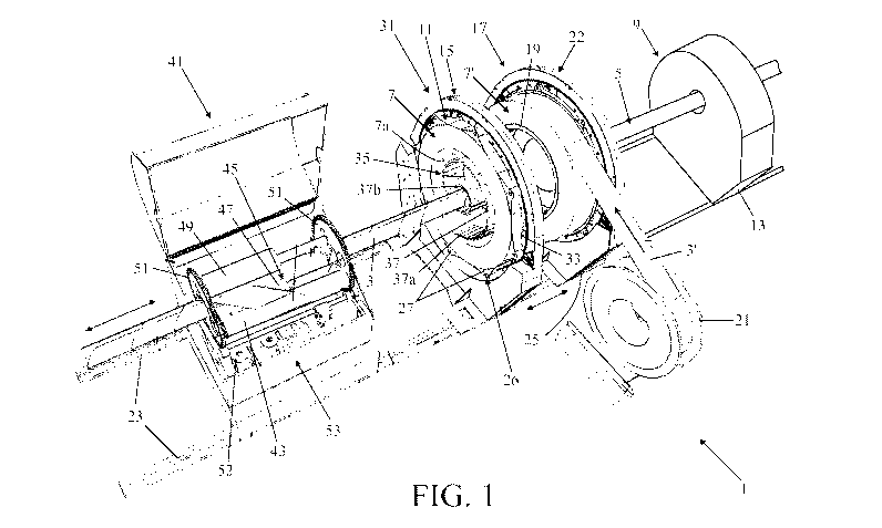
Figure 1 shows the tape application device in a perspective view during
operation with a tape guide curved along a two-dimensional spiral;
Fig. 2 shows the tape feed unit of the tape application device shown in
Fig. 1 during the installation of a new, full roll;
Fig. 3 shows the tape feed unit shown in Fig. 2 with an almost unwound
roll;
Fig. 4 shows the fastening unit of the tape application device shown in
Fig. 1 in a cross-sectional view;
Figure 5 shows another embodiment of the fastening unit with which
more than one tape can be wound on the tube;
Figure 6 shows the winding unit of the tape application device shown in
Figure 1; and
Figure 7 shows the tape feed unit with an alternative embodiment of the
tape guide.
Detailed description of the drawings
Fig. 1 shows in a perspective view an embodiment of the tape application
device 1 according to the invention for helically application a tape 3, 3' on
a tube 5
during operation. The tape is, for example, a bonded thermoplastic composite
which is
wound into a centerless roll 7, 7'. The tape application device has a tube
holder 9 for
CA 03075239 2020-01-17
WO 2019/017777 6 PCT/NL2018/050491
holding the tube and a roll retainer 11 which retains the roll during the
application
operation. The tape application device further has displacement means for
rotating and
translating the tube holder and roll retainer relative to each other. These
displacement
means are formed by translation means 13 which can displace the tube holder in
a
direction parallel to the axis of the tube and rotation means 15 which can
rotate the roll
retainer about the axis of the tube. By rotating the roll 7 and displacing the
tube 5, the
tape 3 is taken from the inside 7a of the roll and helically wound on the
outside of the
tube.
The tape 3' is made into a centerless roll 7' in a winding unit 17. In Fig. 4
this winding unit is shown separately. This winding unit has a spreading
mandrel 19 on
which the tape 3' is wound which originates from a feed reel 21. The tape is,
for
example, a Fiber Reinforced Thermoplastics tape (FRT tape). To this end, the
winding
unit is provided with winding means 22 for rotating the spreading mandrel. The
winding
unit is present on a guiding element 23, see Fig. 1, and can be displaced
towards and
from the roll retainer 11 by further displacement means 25. In the roll
retainer the roll 7
is supported only on the outside by support means 26. These support means are
formed
by suction cups 27 which retain the roll on the outside. Arriving at the roll
retainer 11
the diameter of the spreading mandrel 19 is reduced, after which the winding
unit 17 is
moved back. For mutually connecting the tape windings, the winding unit is
provided
with spot welding means 29, see Fig. 6, which locally weld the newly wound
tape 3' on
the underlying winding by means of weak spot welds which are easy to break.
The helical arrangement of the tape on the tube is effected by a tape feed
unit 31, see Fig. 1, which, in addition to the suction cups 27 for retaining
the roll 7 and
the rotation means 15 for rotating a ring 33 on which the suction cups 27 are
present,
furthermore includes guide means 35 for guiding the tape from the inside 7a of
the roll
to the outside of the tube 5. These guide means are formed by a resilient
spiral tape
guide 37 which is curved along a two-dimensional spiral. During operation, the
tape
guide having a resilient end 37a is fitted to the inside 7a of the roll 7. The
other end 37b
of the tape guide is present close to the tube 5. The tape guide 37 is
connected to further
rotation means (present within the rotation means 15 and therefore not visible
in Fig. 1)
which form part of said displacement means.
During the application operation the displacement means rotate and
translate the roll retainer, the tube holder and the guide means relative to
each other.
The roll retainer 11 and the tape guide 37 are then rotated in the same
direction but at
CA 03075239 2020-01-17
WO 2019/017777 7 PCT/NL2018/050491
different speeds. The helical pitch with which the tape 3 is arranged on the
tube 5 may
be varied by changing the speeds of the translation of the tube 5 and the
rotation of the
roll 7. For example, there may be opted for applying the tape with a pitch
twice the
width of the tape, after which a further tape application device in similar
manner winds
a further tape on the tube in the gap between the tape windings already
present. Further
down the line, two further tape application devices may be installed to wind
two further
tapes in opposite directions over the tapes already present. This may be
expanded at
will. For example, the application of the tapes on a tube may take place
directly after the
extrusion of the tube. With the tape application device according to the
invention the
application of the tape may be performed at high speed so that the extrusion
process
may be kept up with. This is not possible with the known tape application
device.
In the tape feed unit 31, the tape is fed to the tube 5 by the spiral tape
guide 37 and is fastened to the tube a single time. The linear movement of the
tube
draws the tape out of the center of the rotating spiral tape guide and thereby
forms a
helix. The flexible tape guide 37 is continuously resiliently in contact with
the tape on
the inside 7a of the roll and scrapes over the inside and thereby breaks the
spot welds.
As the inner diameter of the roll increases, so does the outer diameter of the
spiral
guide. This is illustrated with reference to Figs. 2 and 3, where in Fig. 2
the tape feed
unit is shown during the application of a new, full roll 7 and in Fig. 3 the
tape feed unit
is shown with an almost unwound roll.
For fastening the tape 3 helically wound on the tube 5, the tape
application device has a fastening unit 41. Figure 4 shows the fastening unit
of the tape
application device in a cross-sectional view. The fastening unit has a
diverting roller 43
which is parallel to and remote from the tube. The diverting roller guides the
tape away
from the tube and back to the tube again. Between the tube and the diverting
roller and
between the tape parts 3a and 3b extending from the tube to the diverting
roller and
from there back to the tube again, fasteners 45 are present. These fasteners
are formed
by heating means 47 (IR heater) and heat the side of the tape facing the tube
so that this
tape becomes sticky (up to the melting temperature). Subsequently, the tape is
stuck to
the tube, with pressure rollers 49 providing the necessary pressure force. The
fasteners
45 are rotated around the tube 5 together with the diverting roller 43 and the
pressure
rollers 49. For this purpose they are connected to toothed wheels 51 which are
rotated
by rotating means 52. The fasteners 45 with diverting roller 43 and pressure
rollers 49
CA 03075239 2020-01-17
WO 2019/017777 8 PCT/NL2018/050491
and the toothed wheels 51 are located in a vacuum chamber 53 to prevent air
and dirt
inclusions between the tape and the tube from occurring during heating and
pressing.
For application a further tape on the tube and / or tape already wound on
the tube in addition to the aforementioned tape, the tape application device
may be
provided with a further roll retainer, as well as further displacement means
for rotating
about an imaginary axis and translating in the direction of the imaginary axis
the tube
holder and further roll retainer relative to each other, such that a further
tape is taken
from the inside of the further roll and is wound helically on the outside of
the tube and /
or on the tape already present on the tube. In that case, the tape application
device may
furthermore be provided with a further fastening unit. However, alternatively
it is
possible to use a fastening unit that can fasten both the tape 3 and the
further tape 4 to
the tube 5. The interior of such a fastening unit is shown in Fig. 5. This
fastening unit
41' has, in addition to the diverting roller 43, a further diverting roller
43' which is
parallel to and spaced apart from the tube and which guides the further tape 4
from the
tube 5 and back to the tube again. The fastening unit 41' furthermore has
further
fasteners (not shown in the figure and, for example, again embodied as heating
means)
which are located between the tube 5 and the further diverting roller 43'. The
rotation
means 52 also rotate the further diverting roller 43' together with the
further fasteners
around the tube 5.
The tube 5 is linearly conveyed through the center of the winding unit 17,
the tape feed unit 31 and the fastening unit 41 during the winding operation.
By
installing winding units alternately and one behind the other, a production
line is created
which can provide a tube with several layers of the tape where two successive
layers are
wound in opposite directions.
Although in the foregoing the invention has been explained with
reference to the drawings, it should be noted that the invention is by no
means limited to
the embodiment shown in the drawings. The invention also extends to any
embodiments
deviating from the embodiment shown in the drawings within the framework
defined by
the claims.
For example, the helical tape guide may have a helical shape with a
continuously increasing diameter seen along the axis. A tape feed unit 31 with
a tape
guide 37' which is curved along a 3-dimensional spiral shape is shown in Fig.
7 by way
of illustration. Alternatively, the roll and / or the tape guide may stop and
the tube may
CA 03075239 2020-01-17
WO 2019/017777 9 PCT/NL2018/050491
also make a rotary movement in addition to the translating movement, or the
tube may
stop and the roll, in addition to rotating, may be moved axially across the
tube.
Due to the resilient action of the tape, fastening of the windings to each
other is not always necessary; this depends on the resilient properties of the
tape. The
windings would not need at all to be fastened to each other or only the
outermost
winding or windings could be fastened.