Note : Les descriptions sont présentées dans la langue officielle dans laquelle elles ont été soumises.
CA 02889166 2015-04-21
WO 2014/066643 PCT/US2013/066624
ACRICULTURAL ROW UNIT SYSTEMS, METHODS, AND APPARATUS
BACKGROUND
[0001] In recent years, growers of corn and other crops have come to recognize
the importance
of planting individual seeds at the appropriate spacing. Due to the time
constraints caused by
field conditions and weather, modern row units have been developed that
include features which
improve seed singulation and spacing even at higher speeds. However, the time
required to set
up these features for planting can delay planting operations, as can errors in
planter setup which
interfere with operation. Thus, there is a need for a row unit having improved
setup features
allowing for more efficient and effective configuration of the row unit prior
to planting
operations.
DESCRIPTION OF THE DRAWINGS
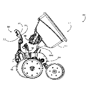
[0002] FIG. IA is a left side elevation view of an embodiment of an
agricultural row unit in an
operating position.
[0003] FIG. 1B is a left side elevation view of the agricultural row unit of
FIG. IA in a partially
disassembled position.
[0004] FIG. IC is an enlarged partial left side elevation view of the
agricultural row unit of FIG.
1B.
[0005] FIG. 2A is a right side elevation view of the agricultural row unit of
FIG. IA in the
operating position.
[0006] FIG. 2B is a right side elevation view of the agricultural row unit of
FIG. 2A in the
partially disassembled position.
[0007] FIG. 2C is an enlarged partial right side elevation view of the
agricultural row unit of
FIG. 2B.
[0008] FIG. 3A is a rear perspective view of the agricultural row unit of FIG.
IA in the operating
position.
1
CA 3077931 2020-04-16
CA 02889166 2015-04-21
WO 2014/066643 PCTATS2013/066624
[0009] FIG. 3B is a rear perspective view of the agricultural row unit of FIG.
3A in the partially
disassembled position.
[0010] FIG. 3C is an enlarged partial rear perspective view of the agicultural
row unit of FIG.
38.
[0011] FIG. 4A is a front perspective view of the agricultural row unit of
FIG. IA in the
operating position.
[0012] FIG. 4B is a front perspective view of the agricultural row unit of
FIG. 4A in the partially
disassembled position.
[0013] FIG. 4C is an enlarged partial front perspective view of the
agricultural row unit of FIG.
4B.
[0014] FIG. 5 is a front elevation view of the agricultural row unit of FIG.
lA in the operating
position.
[0015] FIG. 6A is a left side elevation view showing a portion of an
embodiment of a seed
conveyor and an embodiment of a seed meter in a first partially disengaged
position
correspondin R to a first partially disassembled position of the agricultural
row unit of FIG. 1A.
10016] FIG. 68 is a left side elevation view of the seed conveyor and seed
meter of FIG. 6A in a
second partially disengaged position corresponding to a. second partially
disassembled position
of the agricultural row unit of FIG. IA.
[0017] FIG. 7A is a right side elevation view of the seed conveyor and seed
meter of FIG. 6A.
[0018] FIG. 7B is a right side elevation view of the seed conveyor and seed
meter of FIG. 6B,
[0019] FIG. g is a front elevation view of the seed conveyor and seed meter of
FIG. 6B.
[0020] FIG. 9 is an upward perspective view of the seed conveyor and seed
meter of FIG. 6A.
[0021] FIG. 10A is a view of the agricultural row unit of FIG. IA along the
section 10-10 of
FIG. 5.
2
CA 3077931 2020-04-16
CA 02889166 2015-04-21
WO 2014/066643 PCT/US2013/066624
[0022] FIG. 10B is an enlarged detailed view of the circled portion of the
agricultural row unit of
FIG. 10A.
[0023] FIG. 11 schematically illustrates an embodiment of a planter 10.
[0024] FIG. 12A is a partial right side elevation view of another embodiment
of an agricultural
row unit including a seed tube.
[0025] FIG. 12B is a left side elevation view of another embodiment of the
agricultural row unit
of FIG. 12A.
[0026] FIG. 12C is a partial right side elevation view the agricultural row
unit of FIG. 12A in a
partially disassembled position.
[0027] FIG. 13 schematically illustrates another embodiment of a planter 10
including a
separable electrical connector.
[0028] FIG. 14 is a view of the agricultural row unit of FIG. IA along the
section 10-10 of FIG.
5, in which a spring is replaced with an embodiment of a spring mount.
[0029] FIG. 15A is a side elevation view of the spring mount of FIG. 14 in a
deflected position.
[0030] FIG. 15B is a side elevation view of another embodiment of a spring
mount in a deflected
position.
DESCRIPTION
[0031] Referring now to the drawings, wherein like reference numerals
designate identical or
corresponding parts throughout the several views, FIG. IA illustrates an
agricultural implement,
e.g., a planter, comprising a toolbar 8 to which multiple row units 100 are
mounted in
transversely spaced relation. Each row unit 100 is preferably mounted to the
toolbar 8 by a
parallel arm arrangement 14 including upper and lower parallel arm. pairs 15-
1,15-2,
respectively, such that the row unit is permitted to translate vertically with
respect to the toolbar.
The row unit 100 preferably includes a frame 120 including a forward mounting
post 128 and a
rearward mounting post 122. The upper and lower parallel arm pairs 15-1,15-2
are preferably
3
CA 3077931 2020-04-16
pivotally mounted at a rearward end to the forward mounting post 128. The row
unit 100
preferably includes an opening disc assembly 130 including two angled discs
rollingly mounted
to a shank 165 (FIG. 10A) of the frame 120 and disposed to open a v-shaped
trench in the soil as
the row unit traverses a field. A knife 170 (FIG. 10A) is preferably removably
mounted to the
shank 165. The knife 170 is configured to compress and shape the bottom of the
furrow opened
by the opening disc assembly 130. A guard 104 is preferably mounted to the row
unit frame 120
via a guard support 102 mounted to the row unit frame. The guard 104 is
preferably configured
to prevent soil and debris from passing between the opening discs of the
opening disc assembly
130. The row unit 100 preferably includes a gauge wheel assembly 140 including
two gauge
wheels 142 (FIG.5) pivotally mounted to the frame 120 and disposed to roll
along the surface of
the soil, thus limiting the depth of the trench opened by thc opening disc
assembly 130. A
downforce actuator 12 is preferably pivotally mounted to the toolbar g at a
first end and at a
second end to the parallel arm arrangement 14. The downforce actuator is
preferably configured
to impose a controlled downforcc ou the row unit 100 such that full trench
depth is maintained.
A closing wheel assembly 190 comprising two closing wheels is preferably
pivotally coupled to
the frame 120 and disposed to move displaced soil back into the trench.
[0032] Continuing to refer to FIG, IA, seeds arc communicated from a hopper
110 to a seed
meter 400 preferably configured to sin.gulate the supplied seeds. The meter
400 is preferably a
vacuum-type meter such as that disclosed in Applicant's co-pending
international patent
application no. PCTIUS2012/030192 (Pub. No. WO/2012/129442). A vacuum is
imposed within
the meter 400 by movement of air through a vacuum line 420 in fluid
communication with the
meter.
[00331 Referring to FIGs. IA through 3C, the hopper 110 is preferably
pivotally mounted to the
frame 120. The hopper 110 preferably includes a seed storage bin 112 and Left
and right
attachment arms 114-1,114-2, respectively. The left and right attachment arms
114-1,114-2 are
preferably rcleasably pivotally coupled to left and right pivot 124-1,124-2,
respectively. The
pivots 124 are preferably mounted to the rearward mounting post 122. Each
pivot 124 preferably
includes a plastic cylinder partially engaged by a semi-circular surface of
the associated
attachment arm 114.
4
Date Recue/Date Received 2021-07-30
10034] The meter 400 is preferably removably mounted to the hopper 110. In
operation, the
seed meter 400 preferably deposits the supplied seeds into a seed conveyor 500
such as that
disclosed in Applicant's co-pending international patent application no.
PCTIUS2012157327.
The seed conveyor 500 is preferably removab ly mounted to the flame 120 and
preferably
conveys seeds deposited by the meter 400 to a lower end of the conveyor and
deposits the seeds
into the trench. As discussed further herein with respect to FlGs. 12A-12C, in
some
embodiments the seed conveyor 500 is replaced with a seed tube 800. In such
embodiments,
seeds deposited by the meter 400 fall through the seed tube 800 into the
trench.
[003s] Referring to FIG, 10A, the seed conveyor 500 is preferably positioned
in an opening
between opposing sidcwalls 123 of the row unit frame 120. The seed conveyor
500 preferably
includes left and right protrusions 515 which partially constrain the position
of the seed conveyor
500 by contacting a bracket 167 mounted to the shank 165 at a forward end and
extending
rearward to partially enclose the seed conveyor.
[0036] As discussed in detail elsewhere herein, as the hopper 110 is rotated
rearward (clockwise
on the view of FIG. 3) about the pivots 124, the meter 400 rotates with the
hopper 110 and
disengages from the seed conveyor 500. Likewise, as the hopper 110 is rotated
forward
(counter-clockwise on the view of FIG. 113) about the pivots 124, the meter
400 rotates with the
hopper 110 and engages the seed conveyor 500.
Supply Coupler Assembly
[0037] Turning to FIGs. 3C and 4C, a supply coupler assembly 200 is preferably
mounted to the
frame 120. The supply coupler assembly 200 preferably includes a coupler frame
230, which is
preferably mounted to an upper end of the forward mounting post 128. Referring
to FIG. 4C, a
vacuum conduit 210 and a seed supply conduit 220 are preferably mounted to a
forward side of
the coupler frain e 230 such that the vacuum and seed supply conduits extend
forward from the
coupler from c. Referring to FIG. 3C, a rearward opening in the vacuum conduit
210 is
circumferentially surrounded by a seal 231. Referring to FIG. 4C, as the
hopper 110 is rotated
inward (clockwise on the view of FIG. 2C) about the pivots 124 to the
operating position (i.e.,
that illustrated in FIG. 2A), a plate 118-1 mounted to the hopper 110
preferably contacts the seal
Date Recue/Date Received 2021-07-30
CA 02889166 2015-04-21
WO 2014/066643 PCT/US2013/066624
231. The plate 118-1 preferably includes an aperture in fluid communication
with the vacuum
line 420. Thus in the operating position, the plate 118-1 and the seal 231
cooperate to releasably
place the vacuum conduit 210 in fluid communication with the vacuum line 420.
[0038] Referring again to FIG. 3C, a rearward opening in the seed supply
conduit 220 is
circumferentially surrounded by a seat 232. Referring to FIG. 4C, as the seed
hopper 110 is
rotated forward to the operating position, a plate 118-2 mounted to the hopper
110 preferably
contacts the seal 232. The plate 1 1 8-2 preferably includes an aperture in
fluid communication
with a seed storage bin 112 of the hopper 110. Thus in the operating position,
the plate 118-2
and the seal 232 cooperate to releasably place the seed supply conduit 220 in
fluid
communication with the interior or the seed storage bin 112.
[0039] Referring to FIG. 4C, a latch 300 preferably releasably latches the
hopper 110 to the
coupler assembly 200. The latch 300 is preferably a push-to-close latch such
as model no. R4-
20-20-501-10 available from Southco in Concordville, Pennsylvania. As the
hopper 110 is
rotated toward the operating position, a hook 116 preferably enters a slot 236
(FIG. 3C) formed
in the coupler frame 230. When the hopper 110 is in the operating position,
the latch 300
preferably engages the hook 116 such that the hopper 110 is latched in the
operating position.
When the latch 300 is engaged, the seals 131,132 are preferably compressed
between the plates
118-1,118-2, respectively and the coupler frame 230. When the latch 300 is
released, e.g., by
manipulation of lever 310 (FIG. 5), the hopper 110 is allowed to tip
rearwardly such that the
seals 131,132 separate from the plates 118-1,118-2.
[0040] Turning to FIG. 11, the supply coupler assembly 200 is illustrated
schematically on a
planter 10 having multiple row units 100 transversely spaced along the toolbar
8. Each seed
supply conduit 220 is preferably in fluid communication with a bulk seed
hopper 730 via a seed
supply line 712. The bulk seed hopper 730 is preferably supported by the
toolbar 8. The bulk
seed hopper 730 is preferably configured to pneumatically supply seed (e.g.,
using a blower and
manifold as described in U.S. Patent No. 5,392,722) to each hopper 110. Each
vacuum conduit
2.10 is preferably in fluid communication with a vacuum source 720 (e.g., an
impeller-driven
vacuum pump) via a vacuum line 711.
6
CA 3077931 2020 -04 -16
CA 02889166 2015-04-21
WO 2014/066643 PCIAIS2013/066624
[0041] In some embodiments of the planter 10, the bulk seed hopper 730 is
omitted such that the
individual hoppers 110 are refilled manually. Additionally, even when a bulk
seed hopper 730 is
included, the operator is preferably able to configure the system such that
the bulk seed hopper is
not used. In such embodiments and configurations, the seed supply conduit 220
is preferably
configured to be selectively closed, e.g., with a removable cap 222 (FIG. 5).
Conveyor-Meter Engagement and Disengagement
[00421 Turning to FIGs. 6A through 9, as the hopper 110 is rotated forward
into the operating
position, the meter 400 preferably releasably engages the seed conveyor 500.
It should be
= appreciated that the position and orientation of the seed conveyor 500
relative to the meter 400 in
the operating position is important in establishing successful communication
of seeds from a
seed disc 450 (FIG. 7A) of the meter to the seed conveyor; however, for ease
of removal and
installation, the meter and the seed conveyor are preferably engageable and
disengageable by
simple rotation of the hopper 110. Referring to FIGs. 8 and 9, the meter 400
preferably includes
a vacuum housing 415 and a seed housing 430 including a pocket 432 configured
to receive seed
from the hopper 110. The vacuum housing 415 preferably includes a guide 424
having a guide
surface 426. The seed housing 430 preferably includes a guide 434 having a
guide surface 436.
The seed conveyor 500 preferably includes a vertical alignment fin 510. As the
hopper 110 is
rotated forward into the operating position, the guide surfaces 426,436 guide
the fin 510 between -
the guides 424,434. In. the operating position, the guides 424,434 constrain
the transverse
position (the left-right position on the view of FIG. 8) of the seed conveyor
500 relative to the
meter 400 as well as the vertical orientation of the seed conveyor (along a
plane normal to the
page in FIG. 8) such that seeds arc effectively communicated from the seed
conveyor to the
meter.
[0043] Comparing FIG. 6A to FIG. 613 and FIG. 7A to FIG. 7B, the meter 400 is
illustrated in
two positions as the hopper 110 is rotated forward, progressively engaging the
meter with the
seed conveyor 500. Referring to FIGs. 7A and 7B, the seed conveyor 500
preferably includes a
protrusion 538 at an upper end, and the seed housing 430 of the meter 400
preferably includes a
corresponding pocket 438 configured to receive the protrusion 538. As best
illustrated in FIG.
4A, in the operating position the pocket 438 retains the fore-aft position
(the left-right position
7
CA 3077931 2020-04-16
CA 02889166 2015-04-21
WO 2014/066643 PCT1US2013/066624
on the view of FIG. 7B) of the seed conveyor 500 relative to the meter and
limits the upward
vertical movement of the seed conveyor relative to the meter.
[0044] In order to allow the seed conveyor 500 to be guided into the desired
position by the
meter 400, the seed conveyor is preferably flexibly mounted to the row unit
frame 120. In order
to maintain the seed conveyor 500 in the desired position relative to the
meter 400, the seed
conveyor is preferably resiliently mounted and biased toward engagement with
the meter 400.
As illustrated in FIG. 10A and 10B, the seed conveyor 500 is preferably
supported by a spring
160. The spring 160 is preferably pivotally supported by a post 121 within the
row unit frame
120. Counter-clockwise rotation of the spring 160 (on the view of FIG. 10) is
preferably limited
by contact of a rearward end of the spring with the row unit frame 120. The
seed conveyor 500
preferably includes a mounting tab 560 which rests in an aperture in the
spring 160, fixing the
position and orientation of the seed conveyor relative to the aperture. When
the only other force
acting on the seed conveyor 500 is gravity (acting vertically on the view of
FIG. 10), the spring
160 is preferably configured to resiliently retain the seed conveyor 500 in a
natural position
slightly above and slightly forward of the position in which the seed conveyor
is fully engaged
with the meter 400. The spring 160 is preferably configured to impose an
upward biasing force
Fby on the seed conveyor 500 when the meter 400 imposes a downward force on
the seed
conveyor. The spring 160 is preferably configured to impose a rearward biasing
force Fbx on
the seed conveyor 500 when the meter 400 imposes a forward force on the seed
conveyor. Such
a forward force is imposed, e.g., by the guide 434 on a surface 514 of the
seed conveyor adjacent
to the guide fin 510 (FIG. 8). Thus in the operating position, the spring 160
biases the seed
conveyor 500 against the meter 400 such that the position of the seed conveyor
relative to the
meter is resiliently maintained. Moreover, as the hopper 110 is rotated
rearward and the seed
conveyor 500 returns to its natural position, the meter 400 disengages from
the seed conveyor
without the use of tools_
[0045] In the alternative embodiments illustrated in FIGs. 14-15B, the spring
160 is replaced
with a spring mount 1400. The spring mount 1400 preferably includes a rim 1420
sized to rest
on the row unit frame and a center portion 1410 resiliently displaceable
relative to the rim, to a
= downwardly deflected position such as that illustrated in FIGs. 15A and
15B. In the embodiment
of FIG. 15A, the center portion 1410 displaces with respect to the rim 1420 by
bending of a joint
8
=
CA 3077931 2020-04-16
CA 02889166 2015-04-21
WO 2014/066643 PCTILTS2013/666624
1430; the joint 1430 preferably biases the center portion toward a position
parallel to the rim
1420 (illustrated in FIG. 14). In the embodiment of spring mount 1400' of FIG.
15B, the center
portion 1410 displaces with respect to the rim 1420 by deflection of a coil
spring 1440; in this
embodiment the center portion 1410 is pivotally mounted to the rim 1420 and
the coil spring
1440 biases the center portion toward a position parallel to the rim 1420
(illustrated in FIG. 14).
The center portion 1410 preferably includes an opening 1416 sized allow a
lower portion of the
seed conveyor 500 to pass therahrough. Thc center portion 1410 preferably
includes (or has
mounted thereto) a downwardly extending hook 1412 configured to releasably
engage the
mounting tab 560 of the seed conveyor 500. In an installation phase, the
operator preferably
places the spring mount 1400 on the row unit frame 120 above an opening formed
by sidewalls
123; the operator then preferably slides the lower portion of the seed
conveyor 500 downward
through the opening 1416 until the hook 1412 engages the mounting tab 560.
Thus in operation,
the spring mount 1400 supports the seed conveyor 500 and biases the seed
conveyor vertically
upward for resilient engagement with the seed. meter.
Seed Tube Embodiments
[0046] Turning to FIGs. 12A through 12C, a modified row unit 100' having a
seed tube 800
instead of a seed conveyor is illustrated. The row unit 100' includes a
modified hopper 110'
configured to releasably engage a coupler assembly 200'. When a latch 300' is
released, the
hopper 110' is removed by rearward rotation (counter-clockwise on the
perspective of FIG. 12A)
about pivots 124'. The row unit 100' preferably includes a modified seed meter
400' mounted to
the hopper 110'. The meter 400' is preferably in fluid communication with a
vacuum source via
a modified vacuum line 420' and the coupling assembly 200'. The seed meter
400' preferably
includes an adapter funnel 490 configured to engage the seed tube 800 (e.g.,
enter an upper end
of the seed tube 800) as the hopper 110' is rotated into the operating
position. The adapter
funnel 490 thus establishes seed communication between the meter 400 and the
seed tubc 800.
In the operating position, seeds arc delivered from the meter 400' to the seed
tube 800 via the
adapter funnel 490. The adapter furmel 490 is preferably configured to
disengage from the seed
tube 800 when the hopper 110' is rotated rearward.
[0047] It should be appreciated that in some implementations, the user may
prefer to use the
9
CA 3077931 2020-04-16
= CA 02889166 2015-04-21
WO 2014/066643 PCT/US2013/066624
same planter 10 to plant with seed tubes and seed conveyors. For example, the
user may prefer
to plant certain crops (e.g., corn) with a seed conveyor and other crops
(e.g., smaller-seed crops)
with a seed tube. Thus the same hopper 110 is preferably configured to
operably support either
the meter 400 or the modified meter 400'. Additionally, the same row unit
frame 120 is
preferably configured to support either the seed conveyor 500 or the seed tube
800.
Alternative Coupler Assembly Embodiments
[0048] Turning to FIG. 12, a modified row unit 100" is schematically
illustrated having a
separable electrical connector 290. The connector 290 preferably comprises a
plug 292 mounted
to the hopper 110 and a socket 294 mounted to a modified coupler assembly
200". The plug
292 is in electrical communication with a seed sensor 296 disposed to detect
passage of seeds
through the seed conveyor 500. The socket 294 is preferably in electrical
communication with a
processor 298.
[0049] The coupler assembly 200" preferably includes a modified coupler frame
230" having
an opening permitting engagement of the plug 292 and the socket 294. As the
hopper 110 is
rotated into the operating position, the plug 292 engages the socket 294 such
that the plug is in
electrical communication with the socket. Thus in the operating position, the
processor 298 is in
electrical communication with the seed sensor 296 via the connector 290. When
the hopper 110
is rotated rearward for removal of the hopper, the plug 292 separates from the
socket 294. In
other embodiments, the coupler assembly 200" includes further separable
connectors 290 by
which power is supplied to the seed conveyor 500 and the seed meter 400.
[0050] The foregoing description is presented to enable one of ordinary skill
in the art to make
and use the invention and is provided in the context of a patent application
and its requirements.
Various modifications to the preferred embodiment of the apparatus, and the
general principles
and features of the system and methods described herein will be readily
apparent to those of skill
in the art. Thus, the present invention is not to be limited to the
embodiments of the apparatus,
system and methods described above and illustrated in the drawing figures, but
is to be accorded
the widest scope consistent with the spirit and scope of the appended claims.
CA 3077931 2020-04-16