Note : Les descriptions sont présentées dans la langue officielle dans laquelle elles ont été soumises.
04/24/2020 05:20
PM Page: 4
IMPLEMENT SUPPORT APPARATUS
=
This disclosure relates to the field of implements for use in industries such
as agriculture,
mining, construction and the like, and in particular to an implement support
apparatus
with a frame and wheels to carry a variety of implements.
BACKGROUND
Implements such as are used in agriculture and various industries such as
mining, road
construction and maintenance, and the like include a wide variety of sizes and
configurations. Implements such as combines, swath ers, sprayers, road
graders, earth
movers, and the like are commonly self-propelled, with the engine, drive
system, and
operators station incorporated into the implement itself Implements such as
air seeders,
cultivators, discs, grain carts, mowers, and the like are more commonly towed
behind a
tractor. Some implements are configured to be mounted directly on a tractor
instead of
being towed behind, such as snowplows mounted on the front end of a tractor,
mowers
mounted under a middle portion of the tractor, and a wide variety of
implements mounted
to the arms of a three point hitch system commonly incorporated on the rear
end of
tractors.
A typical towed implement comprises a frame mounted on wheels, and hitch
attached to
=
the frame and adapted to be connected to a towing vehicle like a tractor. In
some such
implements earth working tools such as furrow openers, shanks, blades, buckets
or the
like are mounted on the frame. Implement controls are provided connecting the
tools to
hydraulic and or electric power sources, typically on the towing vehicle, so
that an
operator on the towing vehicle can control the functions of the implement. It
is also
common to incorporate automatic controls, where implement functions are
controlled
1
2 I 358939v I
CA 3078011 2020-04-24
04/24/2020 05:20
PM Page: 5
automatically according to the location determined by a global positioning
system (GPS)
or the like.
Other implements may comprise a container mounted on the frame for carrying
granular
material such as grain, fertilizer, soil, etc. or for carrying liquids. The
implements can
include spreaders for granular material or sprayer booms for and pumps for
spraying
liquids. The variety of implements used in agriculture, construction, and the
like is large
and varied, however a frame mounted on wheels is common to many of these towed
implements.
United States Published Patent Application Number 2019/0053417 of the present
inventor Beaujot discloses an implement operating apparatus with a U-shaped
support
frame supported on drive wheels, each pivotally mounted about a vertical wheel
pivot
axis. Various implements are configured to perform various operations and can
be
connected to the drive frame. The drive frame and implement move and steer
along a
first travel path or a second travel path oriented generally perpendicular to
the first travel
path.
SUMMARY OF THE INVENTION
The present disclosure provides an implement support frame and hitch mounted
on
wheels that overcomes problems in the prior art.
In a first embodiment the present disclosure provides an implement support
apparatus
comprising a U-shaped support frame comprising a base beam and right and left
substantially parallel side beams extending rearward from corresponding right
and left
portions of the base beam and defining an open implement area between the
right and left
side beams. A hitch assembly is attached at a rear end thereof to a front end
of the
2
21358939v1
CA 3078011 2020-04-24
04/24/2020 05:20
PM Page: 6
support frame and is adapted at a front end thereof for connection to a towing
vehicle.
Right and left frame wheels are mounted to the corresponding right and left
side beams
and support the right and left side beams, and each frame wheel is rotatable
about a frame
wheel axis that is fixed in a substantially horizontal orientation
perpendicular to an
operating travel direction that is substantially aligned with the right and
left side beams.
First and second implements are each configured to perform an implement
operation and
to rest on the ground surface when in an idle position. The first and second
implements
and the support frame are configured such that when each implement is in the
idle
position, the support frame is movable, when connected to and propelled by the
towing
vehicle, rearward with respect to each implement to an implement loading
position where
each implement is connectable to the support frame and is movable to an
operating
position where each implement is supported by the support frame and is
connectable to
=
an implement control system operative to control implement functions. Each of
the first
and second implements provides a beam lock connection between the right and
left side
beams and when each of the first and second implements is in the operating
position, the
beam lock connection resists twisting movement of the right and left side
beams to
maintain the right and left frame wheels and the right and left side beams in
a
substantially fixed relationship with respect to each other.
In a second embodiment the present disclosure provides an implement support
apparatus
comprising a U-shaped support frame comprising a base beam and right and left
substantially parallel side beams extending rearward and sloping downward from
corresponding right and left portions of the base beam and defining an open
implement
area between the right and left side beams. A hitch assembly is attached at a
rear end
thereof to the support frame and is adapted at a front end thereof for
connection to a
towing vehicle. Right and left frame wheels are mounted to the corresponding
right and
left side beams and support the right and left side beams, and each frame
wheel is
rotatable about a corresponding frame wheel axis that is fixed in a
substantially
3
21355939v1
CA 3078011 2020-04-24
04/24/2020 05:20
PM Page: 7
horizontal orientation perpendicular to an operating travel direction that is
substantially
aligned with the right and left side beams. First and second implements are
each
configured to perform an implement operation and to rest on the ground surface
when in
an idle position. The first and second implements comprise a front implement
load
support and right and left rear implement load supports. The first and second
implements
and the support frame are configured such that when each implement is in the
idle
position, the support frame is movable, when connected to and propelled by the
towing
vehicle, rearward with respect to each implement to an implement loading
position where
each implement is connectable to the support frame and is movable to an
operating
= 10 position where each implement is supported on the front implement load
support and on
the right and left rear implement load supports by a corresponding front
bearing member
mounted to the support frame and corresponding right and left rear bearing
members
attached to the corresponding right and left side beams and where each
implement is
connectable to an implement control system operative to control implement
functions.
in a third embodiment the present disclosure provides an implement support
apparatus
comprising a U-shaped support frame comprising a base beam and right and left
substantially parallel side beams extending rearward from corresponding right
and left
portions of the base beam and defining an open implement area between the
right and left
side beams, and wherein a width of the open implement area between the right
and left
side beams is adjustable. A hitch assembly is attached at a rear end thereof
to a front end
of the support frame and is adapted at a front end thereof for connection to a
towing
=
vehicle. Right and left frame wheels are mounted to the corresponding right
and left side
beams and support the right and left side beams. Each frame wheel is rotatable
about a
frame wheel axis that is fixed in a substantially horizontal orientation
perpendicular to an
operating travel direction that is substantially aligned with the right and
left side beams.
First and second implements are each configured to perform an implement
operation and
to rest on the ground surface when in an idle position. The first and second
implements
4
21355939v1
CA 3078011 2020-04-24
04/24/2020 05 :
20 PM Page: 8
and the support frame are configured such that when each implement is in the
idle
position, the support frame is movable, when connected to and propelled by the
towing
=
vehicle, rearward with respect to each implement to an implement loading
position where
each implement is connectable to the support frame and is movable to an
operating
position where each implement is supported by the support frame and is
connectable to
an implement control system operative to control implement functions. The
width of the
open implement area is adjusted to a first width to support the first
implement and the
-width of the open implement area is adjusted to a second width to support the
second
= implement.
The present disclosure provides an implement support frame mounted on frame
wheels.
The implement frame includes a hitch assembly and is towed along a length wise
path
aligned with the side beams. Implements of different configurations can be
manufactured
without a frame, hitch, and wheels, and then installed on the support frame.
Heavy
= 15 implements can be carried by the implement support
apparatus because it is configured to
resist torque forces caused by implement weights that are off set from the
support frame
wheel paths and also caused by turning and by sloping ground. The frame wheels
rotate
about rotational axes that are rigidly fixed to the side beams of the support
frame.
DESCRIPTION OF THE DRAWINGS
While the invention is claimed in the concluding portions hereof, preferred
embodiments
are provided in the accompanying detailed description which may be best
understood in
conjunction with the accompanying diagrams where like parts in each of the
several
diagrams are labeled with like numbers, and where:
Fig. 1 is a schematic top view of a support frame of the implement operating
apparatus
=
of the present disclosure;
5
21358939v1
CA 3078011 2020-04-24
04/24/2020 05:20
PM Page: 9
=
Fig. 2 is a schematic front view of the support frame of Fig. 1;
Fig. 3 is a schematic side view of the support frame of Fig. I connected to a
towing
vehicle;
= Fig. 4 is a schematic side view of first and second implements of the
implement
operating apparatus for mounting on the support frame of Fig. 1;
Fig. 5 is a schematic rear view of the first implement of Fig. 4 in the
operating position
on the support frame of Fig. 1;
= Fig. 6 is a schematic side view of the implement apparatus of Fig. 5;
Fig. 7 is a schematic side view showing the attachment of the beam lock
connection of
the implement apparatus of Fig. 5;
Fig. 8 is a schematic top view of an alternate support frame and implement
with
alternate the beam attachment assemblies and beam lock connections;
Fig. 9 is a schematic rear view of a further alternate support frame and
implement with
further alternate beam attachment assemblies and beam lock connections;
Fig. 10 is a schematic detail showing beam attachment assemblies and beam lock
connection of Fig. 9;
6
2 I 355939v1
=
CA 3078011 2020-04-24
04/24/2020
05 : 20 PM Page: 10
Fig. 11 is a schematic side view of an alternate support frame and implement
configured to align the implement weight above portions of the frame wheel
paths to
reduce torque forces;
Fig. 12 is a schematic rear view of the support frame and implement of Fig. 11
where
the frame wheels are directly below the side beams and the implement rests on
the side
beams;
Fig. 13 is a schematic rear view of an alternate arrangement where the frame
wheels
are mounted laterally offset from the corresponding side beams and bearing
members
are rigidly fixed to the right and left side beams and extend laterally to
support the
implement weight above portions of the frame wheel paths;
Fig. 14 is a schematic side view of' the support frame of Fig. 11 with the
hitch
assembly in a level position and ground engaging tools of an implement
penetrating
the ground to a level working depth;
Fig. 15 is a schematic side view of the support frame of Fig. 11 with the
hitch
assembly in a raised position and ground engaging tools of an implement
penetrating
the ground to a reduced working depth;
Fig. 16 is a schematic side view of a support frame supported on tracks;
Fig. 17 is a schematic side view of an implement operating apparatus where the
implement moves to the operating position on rollers;
Fig. 18 is a schematic side view of an implement in the idle position where
the
implement has wings, and where the wings extend forward in the idle position;
7
21358939v1
CA 3078011 2020-04-24
04/24/2020 05:20
PM Page: 11
Fig. 19 is a schematic top view showing the implement of Fig. 18 in the
operating
position on a support frame and in a transport configuration;
Fig. 20 is a schematic top view showing the implement of Fig. 18 in the
operating
position on a support frame and in an operating configuration with the wings
extending
laterally;
Fig. 21 is a schematic top view of a support frame and implement where the
implement
is guided to the operating position by rub guides bearing against rub
surfaces;
Fig. 22 is a schematic side view of the support frame and implement of Fig.
21;
Fig. 23 is a schematic side view of a support frame where the right and left
side beams
slope downward from the base beam at a beam angle, and the implement comprises
load points along a load line sloping downward from the forward portion of the
implement at an angle substantially the same as the beam angle;
Fig. 24 is a schematic side view of an alternate support frame supported on
tracks
where the right and left side beams slope downward from the base beam at a
beam
angle, and the implement comprises a load brace sloping downward from the
forward
portion of the implement at an angle substantially the same as the beam angle;
Fig. 25 is a schematic top view of an alternate support frame with downward
sloping
side beams, hitch hydraulic cylinders to move the hitch assembly up and down,
and
beam attachment assemblies attached to rear ends of the side beams directly
behind the
frame wheels;
8
21355939v1
CA 3078011 2020-04-24
04/24/2020 05 :
20 PM Page: 12
Fig. 26 is a schematic side view of the support frame of Fig. 25;
Fig. 27 is a schematic rear view of the support frame of Fig. 25;
Fig. 28 is a schematic side view of the support frame of Fig. 25 in the
implement
loading position with respect to an implement, with the hitch assembly pivoted
upward
to lower the base beam
Fig. 29 is a schematic side view of the support frame and implement of Fig. 28
with
the implement in the implement operating position, with the hitch assembly
pivoted
downward to raise the base beam and the implement;
Fig. 30 is a schematic sectional side view of the beam attachment assembly and
beam
lock connection of the support frame and implement in the implement loading
position
of Fig. 28;
Fig. 31 is a schematic bottom view showing the relative positions of the lock
plates on
=
the implement and the pins of the beam attachment assemblies when the support
frame
and implement are in the implement loading position of Fig. 33;
Fig. 32 is a schematic sectional side view of the beam attachment assembly and
beam
lock connection of the support frame and implement in the operating position
of Fig.
29;
=
Fig. 33 is a schematic bottom view showing the relative positions of the lock
plates on
the implement and the pins of the beam attachment assemblies when the
implement is
in the operating position of Fig. 33 on the support frame;
9
21358939vI
CA 3078011 2020-04-24
04/24/2020 05:20
PM Page: 13
Fig. 34 is a schematic top view of an alternate support frame where the width
of the
open implement area between the side beams is adjustable;
Fig. 35 is a schematic front view of the support frame of Fig. 34;
=
Fig. 36A is a schematic top view of the support frame of Fig. 34 with the open
implement area adjusted to a first width moving rearward into the loading
position
with respect to a first implement;
Fig. 36B is a schematic top view of the support frame of Fig. 34 with the open
implement area adjusted to a second narrower width moving rearward into the
loading
position with respect to a second implement;
Fig. 37 is a partially cut away schematic top view an alternate base beam
where two
beam hydraulic cylinders are mounted inside the center beam segment, each
connect to
one of the right and left beam segments;
Fig. 37A is schematic sectional end view along line 37A in Fig. 37;
Fig. 38 is a schematic front view of a hitch assembly pivotally mounted to the
center
beam segment of the base beam;
Fig. 39 is a schematic side view of the hitch assembly of Fig. 38;
Fig. 40 is a schematic top view of an alternate hitch assembly pivotally
mounted to the
right and left beam segments;
Fig. 41 is a schematic front view of the hitch assembly of Fig. 40;
2 I 35 g939v I
CA 3078011 2020-04-24
04/24/2020
05:20 PM Page: 14
Fig. 42 is a schematic side view of the hitch assembly of Fig. 40;
Fig. 43 is a schematic top view of an alternate support frame where right and
left beam
segments are fixed to corresponding right and left side beams and where the
right beam
segment slides telescopically into the left side beam;
Fig. 44 is a schematic top view of an alternate support frame shown with a
wide open
area where the width of the open area is changed by exerting towing forces on
the hitch
assembly;
Fig. 45 is a schematic top view of the support frame of Fig. 44 with a
narrower open
implement area.
DETAILED DESCRIPTION OF THE ILLUSTRATED EMBODIMENTS
Figs. 1 ¨ 4 schematically illustrate an embodiment of an implement support
apparatus 1
of the present disclosure. The apparatus 1 comprises a U-shaped support frame
3
comprising a base beam 5 and right and left substantially parallel side beams
7R, 7L
extending rearward from corresponding right and left portions of the base beam
5 and
defining an open implement area 9 between the right and left side beams 7R,
7L.
Right and left frame wheels I IR, 1 IL are mounted to the corresponding right
and left
side beams 7R, 7L and support the right and left side beams. Each frame wheel
11 is
rotatable about a frame wheel axis FWA that is fixed in a substantially
horizontal
orientation perpendicular to an operating travel direction T that is
substantially aligned
with the right and left side beams 7.
=
11
2] 35939v I
CA 3078011 2020-04-24
04/24/2020
05:20 PM Page: 15
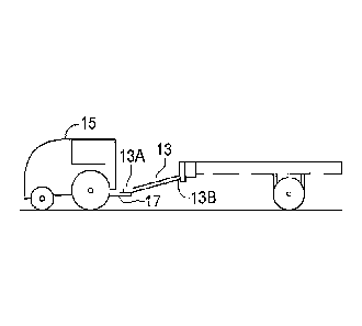
A hitch assembly 13 is attached at a rear end 13B thereof to a front end of
the support
frame 3 and is adapted at a front end 13A thereof for connection to a towing
vehicle 15.
The illustrated hitch assembly 13 is fixed to the base beam 5 such that a
front portion of
the weight of the support frame 3 and any implement supported thereon is
supported on
the hitch 17 of the towing vehicle 15 and a rear portion of the weight of the
support frame
3 and any implement supported thereon is supported on the frame wheels 11.
First and second implements 21A, 21B are each configured to perform an
implement
operation and to rest on the ground surface 19 when in the illustrated idle
position. The
implements 21 can include a wide variety of implements that might be used in
agriculture, construction, mining and like industries. Fig. 4 shows implements
2IA and
21B. Implement 21A is a hoppered container such as might be used to carry
gravel, grain
or the like with a capacity of 40,000 ¨ 60,000 pounds. Implement 21B is an air
seeder
with folded wings with a width of 50 ¨ 60 feet such as would be used in
agriculture.
IS
The implements 21 and the support frame 3 are configured such that when each
implement is in the idle position, the support frame 3, schematically
illustrated by
phantom lines, is movable rearward with respect to each implement 21 in the
idle
position to an implement loading position where each implement 21 is
connectable to the
support frame 3 and is movable, when connected to and propelled by the towing
vehicle
15, rearward with respect to each implement 21 to an implement loading
position where
each implement 21 is connectable to the support frame 3 and is movable to an
operating
position where each implement 21 is supported by the support frame 3 and is
connectable
to an implement control system operative to control implement functions Once
an
implement 21 is supported on the support frame 3 the stands 25 that support
the
implements 21 in the idle position are removed, folded, or retracted.
12
21358939v I
CA 3078011 2020-04-24
04/24/2020 05 :
20 PM Page: 16
Fig. 5 schematically illustrates a rear view of a typical implement 21
supported on the
right and left side beams 7R, 7L of the support frame 3. The weight of the
implement 21
bears against the side beams 7 along force line WE, and the weight of the rear
portion of
the apparatus 1 including the implement 21 and the support frame 3 is
supported by the
wheels 11 along support force line SF in the center of the wheel path WP. It
can be seen
that where the weight of the implement 21 is high, such as when the implement
is
configured to carry soil, gravel, grain, or the like, a significant torque
force IF is exerted
that will tend to move the wheels 11 outward. Further torque forces TF also
occur when
the apparatus 1 is operating on sloping ground, and while turning, especially
at higher
speeds.
To address this issue, cross members may be incorporated into the support
frame 3
however it would then be necessary to configure every implement to accommodate
the
cross members. It would be possible to remove one cross member and substitute
another
for a particular implement, however this would be laborious and time consuming
and so
in the disclosed apparatus 1, these cross members are incorporated into each
implement
and attach to the support frame 3 during the loading process. Thus each
implement
includes the cross member support required for that particular implement in a
beam lock
connection 22, and the open implement area 9 remains clear.
Each of the first and second implements 21A, 21B provides a beam lock
connection 22
between the right and left side beams 7R, 7L. When each of the implements 21
is in the
operating position, the beam lock connection 22 resists twisting movement of
the right
and left side beams 7R, 7L to maintain the right and left frame wheels1IR, 11L
and the
. 25 right and left side beams 7R, 7L in a substantially fixed relationship
with respect to each
other.
1.3
21355939v I
CA 3078011 2020-04-24
04/24/2020 05:20
PM Page: 17
The right and left side beams 7R, 7L comprise corresponding right and left
beam
attachment assemblies 24R, 24L, each beam attachment assembly 24 fixed to the
corresponding side beam 7. The right beam attachment assembly 24R defines
fixed first
=
and second right beam attachment members 27RA, 27RB that are laterally spaced
from
each other in directions perpendicular to the operating travel direction T,
and the left
beam attachment assembly 24L defines fixed first and second left beam
attachment
members 27LA, 27LB that are laterally spaced from each other in directions
perpendicular to the operating travel direction T., In the illustrated
apparatus 1, the
support frame 3 includes right and left side bars 31R, 31L rigidly attached at
upper
= 10 portions thereof to the corresponding right and left side
beams 7R, 7L, and extending
downward from the corresponding right and left side beams. The second right
and left
attachment members 27RB, 27LB are located at the bottom of the side bars 31
and so are
spaced laterally in a vertical direction with respect to the first right and
left attachment
members 27RA, 27LA.
The beam lock connection 22 comprises rigid elements 29 and 33. The
illustrated
elements 29, 33 form part of the implement 21 that is itself rigid such that
the right and
left ends of the elements 29, 33 are all rigid with respect to each other. As
shown in Fig.
7 the elements 29, 33 engage the first and second right beam attachment
members 27RA,
27RB and the first and second left beam attachment members 27LA, 27LB when
each
implement 21 is in the operating position.
Thus the beam attachment members 27RA, 27RB, 27LA, 27LB are held in a rigid
relationship with respect to each other, and so the right and left frame
wheels 11R, 11L
and the right and left side beams 7R, 7L are maintained in a substantially
fixed
relationship with respect to each other and the torque forces TF are resisted
whether the
apparatus is operating on a level or a sloping ground surface 19. As can be
seen in Figs.
6 and 7 the first and second beam attachment members on each side are also
14
21358939v1
CA 3078011 2020-04-24
04/24/2020
05:20 PM Page: 18
longitudinally spaced in directions parallel to the operating travel direction
T forward and
rearward with respect to each other.
Fig. 6 schematically illustrates a left side view of implement 21 of Fig. 5
supported on the
right and left side beams 7R, 7L of the support frame 3. The elements 29, 33
are
incorporated into the implement 21 and move into engagement with the left beam
attachment members 27LA, 27LB as the support frame 3 moves rearward with
respect to
the implement 21 in response to a force exerted by a loading hydraulic
cylinder 37 as
shown in Fig. 7. In the illustrated apparatus 1 the beam attachment members
27LA,
27LB comprise a recess 39 configured to receive a projection 41. The loading
hydraulic
cylinder 37 is operative to maintain a high forward bias force on the
implement 21 to
maintain the engagement during operation. Alternatively or in addition
mechanical locks
or latches could be provided.
In the illustrated apparatus 1, right and left front side bars 43R, 43L are
rigidly attached
at upper portions thereof to the corresponding right and left side beams 7R,
7L and
extend downward from the corresponding right and left side beams, and the
right and left
rear side bars 31R, 31L are rigidly attached at upper portions thereof to the
corresponding
right and left side beams rearward of the corresponding right and left front
side bars 43R,
43L. A right wheel support 45R is rigidly attached to lower portions of the
right front
and rear side bars 43R, 31R and a left 45L wheel support rigidly attached to
lower
portions of the left front and rear side bars 43L, 3 IL. The right and left
frame wheels
1 IR, 1 IL are mounted to the corresponding right and left wheel supports 45R,
45L.
In the apparatus 1, the vertical distance between the first beam attachment
members
27RA, 27LA and the corresponding second beam attachment members 27R.B, 27LB is
selected to substantially prevent movement of the right and left rear frame
wheels I IR,
11L perpendicular to the operating travel direction T.
21358939v1
CA 3078011 2020-04-24
04/24/2020
05:20 PM Page: 19
Fig. 8 schematically illustrates a version of the beam attachment assemblies
24R', 24L'
with fixed corresponding beam attachment members 27RA', 27RB' and 27LA', 27LB'
that are laterally spaced from each other in a horizontal direction
perpendicular to the
operating travel direction T, and wherein the beam lock connection 22
comprises a rigid
implement portion 29' of the implement 21'. Again the beam attachment members
27'
each comprise a recess 39' configured to receive a projection 41' on the rigid
implement
portion 29'. The beam attachment members 27' and the rigid implement portion
29' are
maintained in engagement by a loading hydraulic cylinder 37 as shown in Fig.
7, or by a
=
latch or manual lock mechanism.
Figs. 9 and 10 schematic illustrate an alternate arrangement where right and
left twist
struts 59R", 59L" are fixed to the corresponding right and left side beams
7R", 7L", and
the beam lock connection 22" comprises right and left twist slots 61R", 61L"
fixed to a
rigid element 29" on each implement 21", and wherein when moving from the idle
position to the operating position the right and left twist slots 61" closely
engage the
corresponding right and left twist struts 59" to resist twisting movement of
the right and
left side beams 7". Here the beam attachment members 27RA'', 27RB' and 27LA",
27LB'
are provided by corners of the slots 61" which bear against the twist struts
59" and
prevent twisting when the implement 21" is in the operating position of Fig. 9
if torque
forces exert twisting forces on the side beams 7".
As schematically illustrated in Fig. 5, a torque force IF results from the
weight of the
implement 21 bearing against the side beams 7 along the weight force line WF
that is
laterally offset from support force line SF in the center of the wheel path WP
of wheels
11 which support the support frame 3. This torque force TF can be removed by
aligning
the force line WF with the force line SF. In the arrangement of Figs. 9 and
10, the weight
of the rear portion of the implement 21" is carried through the rigid element
29" on the
16
21358939v1
CA 3078011 2020-04-24
04/24/2020 05 :
20 PM Page: 20
twist struts 59" which are aligned with the center of the wheel path WP, such
that the
weight force line WF and support force line SF are aligned. Such a weight
distribution
reduces the torque forces however the torque forces resulting from sloping
terrain and
turning the apparatus I still remain, and are resisted by the beam lock
connection 22.
Figs. 11 and 12 schematically illustrate a support frame 103 and an implement
121
configured to align the weight force line and the support force line to reduce
torque
forces. When the implement 121 is in the illustrated operating position, a
front F1W
implement weight of the implement 21 is supported via the hitch assembly 113
on the
towing vehicle hitch 117 and a rear implement weight R1W of each implement is
supported on a rear portion of the support frame which is supported by frame
wheels ll 1.
Because of the typical mounting location with a central portion of the
implement 121
directly above the rear frame wheels 111, the rear implement weight RIW is
significantly
greater than the front implement weight FIW and the frame wheels ill are
typically
quite wide, or can be dual wheels or tracks to support the high loads. The
front
implement weight FIW varies with the implement being carried but does provide
some
ballast to the tractor to increase traction of the towing vehicle wheels and
reduce
slippage.
To align the weight force line WF with the support force line SF, right and
left rear
bearing members 159R, 159L can be fixed to the corresponding right and left
side beams
107R, 107L and located on right and left bearing axes BAXR, BAXL substantially
aligned with the operating travel direction T and directly above paths of the
right and left
frame wheels 111R, 111L. Placing the right and left bearing axes BAXR, BAXL
directly
above the centers of the wheel path as shown is most desirable, however wheel
sizes will
change, dual wheels or tracks might be provided, and like options are
typically present so
17
2135g939v I
CA 3078011 2020-04-24
04/24/2020 05:20
PM Page: 21
the right and left bearing axes BAXR, BAX1 will typically be above some point
on the
width of the frame wheel paths.
= In the rear view of Fig. 12 it can be seen that the implement 121 rests
directly on the side
beams 107 such that the rear bearing members 159 are provided by the side
beams 107,
and the right and left frame wheels 111R, 111L are mounted directly under the
corresponding right and left side beams 107R, 107L, and wherein the right and
left rear
bearing members 159 are located on the right and left side beams. In this
version the
whole weight of the implement 121 is carried on the side beams 107 along the
right and
left bearing axes BAXR, BAXL, with the side beams 107 in turn supported on the
frame
wheels 111 supporting the rear implement weight R1W and the hitch assembly 113
and
towing vehicle hitch 117 supporting the front implement weight F1W. While the
weight
of the implement 121 is carried all along the length of the side beams 107, it
can be seen
that the approximate center gravity CG of the implement 121 will be much
closer to the
rear frame wheels Ill than to the vehicle hitch 117, and so most of the weight
of the
implement 121 is supported on the rear frame wheels 111.
=
To concentrate weight of the implement 121 at a desired location along the
bearing axes,
raised rear bearing members 159A can be provided that coincide with rear
bearing points
159B on the implement 121, instead of bearing the weight of the implement
along the
whole length of the side beams 107. The torque forces are less problematic at
front
portions of the side beams, where they are rigidly fixed to the base beam 105
and twisting
is resisted effectively by the base beam 105.
Fig. 13 schematically illustrates an alternate arrangement configured to align
the weight
force line and the support force line to reduce torque forces. In the
arrangement of Fig.
15, the right and left frame wheels 111R, 111L' are mounted laterally offset
from the
corresponding right and left side beams 107W, 107L' outside the open implement
area
109' and the right and left bearing members 159R', 159L' are rigidly fixed to
the right and
18
2 355939v11
CA 3078011 2020-04-24
04/24/2020 05:20
PM Page: 22
left side beams 107R', 107L' and extend laterally to the corresponding right
and left
bearing axes BAX1V, BAXL'.
=
As seen in Fig. 11 tires 161 are mounted to the frame wheels 111 and bear
against the
ground surface 19 to support the support frame 103.
Figs. 14 and 15 schematically illustrate the support frame 103 wherein the
hitch assembly
113 is pivotally attached at the rear end 113B thereof to the base beam about
a hitch pivot
axis HPA oriented substantially horizontally and perpendicular to the
operating travel
direction T. A hitch hydraulic cylinder 167 is operative to pivot the hitch
assembly 113
upward with respect to the base beam 105 to correspondingly move rear ends of
the right
and left side beams 107 upward and operative to pivot the hitch assembly
downward with
respect to the base beam 105 to correspondingly move the rear ends of the
right and left
side beams 107 downward.
Figs. 14 and 15 schematically illustrate an implement 121' attached to the
rear ends of
the side beams 107 in a substantially fixed position relative to the side
beams 107, such
that the implement 121' moves upward and downward with the rear ends of the
side
beams 107. The system can be used, for example, to adjust the depth of
penetration into
the ground surface 19 of ground engaging tools 171 fixed to the implement
121'. An
implement height sensor 173 is operative to sense a height of the implement
121', and is
connected to the hydraulic source 165 for the hydraulic cylinder 167 on the
towing
vehicle to extend and retract the hitch hydraulic cylinder 167 to maintain the
height of the
implement 121' at a desired height.
Fig. 16 schematically illustrates a support frame 203 where right and left
tracks 275 are
connected to the corresponding tandem right and left frame wheels 211.
19
21358939v I
CA 3078011 2020-04-24
04/24/2020
05:20 PM Page: 23
Fig. 17 schematic illustrates an implement operating apparatus 301 wherein the
implement 321 comprises right and left support plates 377 configured to rest
on the
=
support frame 303. Rollers 379 are mounted to the support frame 303 about
substantially
horizontal rotational axes RA oriented substantially perpendicular to the
operating travel
direction T. When the support frame 303 is in the implement loading position
with
respect to the implement 321 in the idle position illustrated in Fig. 20, the
rollers 379 on
each side of the support frame 303 are under the support plates 377 on each
side of the
implement 321, and as the support frame 303 moves rearward, the implement 321
moves
toward the operating position and the rollers 379 bear against the support
plates 377 and
the implement 321 rolls onto the support frame 303. A roller drive 381 may be
provided
that is operative to selectively rotate one or more of the support rollers 379
in a forward
direction to assist in moving the implement 321 to the operating position,
shown in
phantom lines, and in a reverse direction to move the implement 321 to the
idle position.
Figs. 18 - 20 schematically illustrate an implement 421, such as a spraying
implement,
that includes right and left wings 483. The right and left wings 483 extend
laterally from
the support frame 403 when the implement 421 is in the operating position and
in a
working configuration as shown in Fig. 20, and the wings 483 extend forward
substantially aligned with the operating travel direction T when the implement
421 is in a
transport configuration mounted on the support frame 403 as shown in Fig. 19,
and when
the implement is in the idle position supported on the ground as shown in Fig.
18.
=
The wings 483 are supported in the forward positions of Fig. 18 and 19 by
corresponding
right and left wing supports 485 attached to the implement 421. To minimize
transport
widths, the right and left wings 485 are above the right and left side beams
407 inside the
tires, and inside outer edges 403A of the support frame 403 when in the
transport
configuration and mounted on the support frame 403 such that the wings are no
wider
than the support frame and wheels. In the illustrated support frame 403 the
frame wheels
21358939v1
CA 3078011 2020-04-24
04/24/2020 05:20
PM Page: 24
are directly under the side beams of the support frame. Where the frame wheels
extend
laterally outside the support frame the wings in transport will be inside the
outer edges of
the frame wheels.
Figs. 21 and 22 schematically illustrate a support frame 503 where right and
left rub faces
587 extend along right and left sides of the support frame 503. In the
illustrated support
frame 503 the rub faces are conveniently provided by inner faces of the
corresponding
right and left side beams 507. Corresponding right and left rub guides 589 are
mounted
on the implement 521 and the rub faces 587 and rub guides 589 are configured
such that
when the support frame 503 is maneuvered to the implement loading position of
Fig. 21
with respect to the implement 521 in the idle position, a forward portion of
the implement
=
521 moves into the open implement area 509 between the right and left side
beams 507
and the right and left rub guides 589 contact the corresponding right and left
rub faces to
guide the implement 521 to the operating position.
Each rub guide 589 comprises a guide surface 591 at a front end thereof that
slopes
inward away from the corresponding right and left side beams 507. The
illustrated
implement 521 comprises right and left front rub guides 589F on a forward
portion of the
implement 521 and right and left rear rub guides 589R located on the implement
rearward
of the corresponding right and left front rub guides 589F. Sloping guide
surfaces 591'
could be provided on the rear ends of the side beams 507 as well.
Fig. 23 schematic illustrates a support frame 603 where the right and left
side beams 607
slope downward from the base beam 605 at a beam angle N, and wherein the
implement
621 comprises load points 693 along a load line LL sloping downward from the
forward
portion of the implement at an angle substantially the same as the beam angle
N The
support frame 603 can then be maneuvered to the implement loading position of
Fig. 23
with respect to the implement 621 in the idle position, where the side beams
607 move
21
21358939v1
CA 3078011 2020-04-24
04/24/2020
05:20 PM Page: 25
under the load points 693, and the jacks 625 supporting the implement in the
idle position
can then simply be raised to lower the implement to rest the load points 693
on the
sloping side beams 607.
=
To accommodate the slope of the side beams 607, in the support frame 603 of
Fig. 23, the
right and left frame wheels 611 are mounted laterally offset from the
corresponding right
and left side beams 607 outside the open implement area, and the frame wheels
611
extend above the corresponding right and left side beams.
An alternate arrangement of a support frame 603' is schematically illustrated
in Fig. 24
where frame wheels 611' include a track 675' and are mounted directly under
the
corresponding right and left side beams 607'. The track arrangement allows for
a lower
profile drive assembly , and so can be mounted directly under the side beams
607'. Fig.
24 also illustrates an implement 621' that includes a load brace 695'
extending at the
beam angle N so the implement 621' is supported on the load brace 695' bearing
against
most of the length of the side beams 607', rather than only on the load points
693 in the
arrangement of Fig. 23.
Figs. 25 ¨ 29 schematically illustrate an implement support apparatus 701
comprising a
U-shaped support frame 703 comprising a base beam 705 and right and left
substantially
parallel side beams 707R, 707L extending rearward and sloping downward from
corresponding right and left portions of the base beam 705 and defining an
open
implement area 709 between the right and left side beams 707.
Right and left frame wheels 711R, 711L are mounted to the corresponding right
and left
side beams 707R, 707L and support the side beams 707. Each frame wheel 711 is
rotatable about a corresponding frame wheel axis FWA that is fixed in a
substantially
horizontal orientation perpendicular to an operating travel direction T that
is substantially
aligned with the parallel side beams 707.
22
21358939vI
CA 3078011 2020-04-24
04/24/2020 05:20
PM Page: 26
A hitch assembly 713 is attached at a rear end 713B thereof to the base beam
705 and is
adapted at a front end 7I3A thereof for connection to the hitch 717 of a
towing vehicle
715.
As described above a number of different implements 721 are configured to be
supported
on the support frame 703 for operation. Each implement 721 is configured to
perform an
implement operation and to rest on the ground surface 19 when in an idle
position shown
in Fig. 28 supported on stands 725, and each implement 721 comprises right and
left
front implement load supports 702F and right and left rear implement load
supports
702R. It is contemplated as well that some implements may be supported on a
single
front implement load support.
The implement 721 and the support frame 703 are configured such that when the
implement 721 is in the idle position of Fig. 28, the support frame 703 is
movable
rearward with respect to the implement 721 to an implement loading position
shown also
in Fig. 28 where the implement is connectable to the support frame 703 and is
movable to
an operating position shown in Fig. 29 where the implement is supported on the
front
implement load supports 702F and on the rear implement load supports 702R by
corresponding right and left front bearing members 704F mounted to the support
frame
703 and corresponding right and left rear bearing members 704R attached to the
corresponding right and left side beams 707R, 707L and where the implement 721
is
connected to an implement control system typically on the towing vehicle.
The right and left frame wheels 711R, 711L are mounted laterally offset from
the
corresponding right and left side beams 707R, 707L outside the open implement
area
709, and the frame wheels 71 I extend above the corresponding right and left
side beams
707R, 707L such that the frame wheel axis FWA is in proximity to the side
beams 707
23
21358939v I
CA 3078011 2020-04-24
04/24/2020
05:20 PM Page: 27
and the rear ends of side beams 707 are comparatively close to the ground
surface, about
the height of a conventional tractor drawbar. Where the implement being
operated
includes a trailing load, such as a cultivator with ground engaging tools, the
pulling force
is then exerted pulling on the side beams 707 rather than exerting downward
forces on
the side beams 707, thus reducing stresses on the support frame 703.
As seen in Figs. 25 and 26, the rear bearing members 704R are located rearward
of the
corresponding right and left frame wheels 711 and substantially in alignment
with centers
of corresponding right and left frame wheel paths WP. As discussed above
however
while being centered on the wheel paths WP is most desirable, wheel sizes will
change,
dual wheels or tracks might be provided, and like options are typically
present so the rear
bearing members 704R will typically be aligned some point on the width of the
frame
wheel paths WP.
The right and left rear bearing members 704R are provided by right and left
loading arms
706 pivotally connected to corresponding right and left beam attachment
assemblies 724
attached to rear ends of each side beam 707.
To further facilitate loading the implement 721 onto the support frame 703 the
hitch
assembly 713 is attached at the rear end 713B thereof to the base beam 705
about a hitch
pivot axis 1-IPA oriented substantially horizontally and perpendicular to the
operating
travel direction T. Hitch hydraulic cylinders 767 connected to hydraulic
source 765 are
operative to selectively pivot the hitch assembly 713 upward and downward with
respect
to the base beam 705 and wherein the hitch assembly 713 is pivoted upward to
lower the
. 25 base beam 705 while the support frame 703 is moved rearward to the
implement loading
position of Fig. 28, and the hitch assembly 713 is pivoted downward to raise
the base
beam 705 and force the front bearing members 704F upward to bear against the
corresponding front implement load supports 702F and raise a front portion of
each
implement above the ground to the operating position of Fig. 29.
24
21358939v I
CA 3078011 2020-04-24
04/24/2020
05 : 20 PM Page: 28
When the support frame 703 is in the implement loading position shown in Fig.
28, each
loading arm 706 engages the corresponding rear implement load support 702R on
the
implement 721. A further detail of the rear implement load supports 702R on
the
implement 721 and the beam attachment assemblies 724 on the support frame 703
in the
implement loading position is shown in Fig. 30. A load control 714 is then
operated to
extend the load hydraulic cylinders 716 to move the loading arms 706 to the
position
shown in the detail illustration of Fig. 32, where the rear implement load
support 702R
moves upward and slightly forward from the idle position of Fig. 30, and the
hitch
=
hydraulic cylinders 767 are extended to move the base beam 705 upward and
force the
front bearing members 704F upward to bear against the corresponding front
implement
load supports 702F and raise the front portion of the implement above the
ground, and so
the implement 721 is moved from the idle position to the operating position,
and the
stands 725 can be removed or folded out of the way. The rear implement weight
is
carried on the load arms 706 which provide the rear bearing members 704R and
which
are located in portions the corresponding right and left frame wheel paths WP.
As seen in Figs. 30 - 33 each beam attachment assembly 724 defines upper and
lower
beam attachment members 727A, 727B in the form of pins 718 that are laterally
spaced
vertically from each other. The implement 721 is rigid and includes upper and
lower lock
plates 720A, 720B configured to engage the pins 718 of the upper and lower
beam
attachment members 727A, 727 on each of the right and left beam attachment
assemblies
724 to prevent lateral movement of the pins 718 when the implement 721 is in
the
operating position, as shown in Fig. 33.
Thus it can be seen that once the implement 721 is in the operating position
of Fig. 29,
the load control 714 is then operated to maintain an extending pressure in the
load
hydraulic cylinders 716 to exert a downward bias force BF on the loading arms
706 to
21358939v1
CA 3078011 2020-04-24
04/24/2020 05:20
PM Page: 29
maintain the loading arms 706 and rear implement load supports 702R in fixed
positions,
and maintain the implement 721 in the operating position with the lock plates
720
engaging the pins 718 of the beam attachment members 727A, 727B and forming a
beam
lock connection 722 that resists twisting movement of the right and left side
beams 707R,
707L to maintain the right and left frame wheels 711R, 711L and the right and
left side
beams 707R, 707L in a substantially fixed relationship with respect to each
other. The
implement 721 may be further secured to the support frame 703 by a safety pin
through
holes in safety plates 746 which are aligned when the implement 721 is in the
operating
position as shown in Fig. 32.
In addition, in the apparatus 701 the rear implement weight is supported by
the right and
left rear bearing members, provided by loading arms 706, that are fixed with
respect to
the corresponding side beams and located in portions of the wheel paths WP of
the frame
wheels 711. Since the rear implement weight carried on the right and left rear
bearing
members is at least twice, and often five or six times, as much as a front
implement
weight carried on the right and left front bearing members, the combination of
the beam
lock connection 722, which resists torque forces on the side beams 707, and
the
alignment of the rear implement weight in the wheel paths WP of the frame
wheels 711,
which reduces torque forces, significantly reduces stress on the support frame
703.
=
The hitch hydraulic cylinders 767 also can be used with an implement that is
attached to
the rear ends of the side beams 707 in a substantially fixed position to
adjust the vertical
position of the implement upward and downward. Al so as described above, an
implement height sensor can be added to the elevation control to maintain the
height of
the implement at a desired height.
In the support frame 703 right and left rub faces 787 extend along inner faces
of the
corresponding right and left side beams 707 and right and left rub guides 789
are
mounted on the implement 721. In the illustrated apparatus 701 the rub guides
789 are
26
21358939vI
CA 3078011 2020-04-24
04/24/2020
05 : 20 PM Page: 30
mounted on the front and rear legs 725 supporting the implement 721 in the
idle position.
The rub guides 789 include a guide surface 791 at a front end thereof that
slopes inward
away from the corresponding right and left side beams 707.
When the support frame 703 is maneuvered to the implement loading position
with
respect to the implement 721 in the idle position, the front legs 725 move
into the open
implement area 709 between the side beams 707 and the right and left rub
guides 789
contact the corresponding right and left rub faces 787 to guide the implement
721 to the
operating position.
Figs. 34 ¨ 36 schematically illustrate a further alternate implement support
apparatus 801
comprising a U-shaped support frame 803 comprising a base beam 805 and right
and left
substantially parallel side beams 807R, 807L extending rearward from
corresponding
right and left portions of the base beam 805 and defining an open implement
area 809
between the right and left side beams. Tn this support frame 803 the width W
of the open
implement area 809 between the side beams 807 is adjustable. Fig. 34
schematically
illustrates the support frame 803 where the width of the open implement area
is
adjustable from a first width WI to a second width W2.
A hitch assembly 813 is attached at a rear end 813B thereof to a front end of
the support
frame 803 and is adapted at a front end 813A thereof for connection to a
towing vehicle
as described above. Right and left frame wheels 81 IR, 81 IL are mounted to
the
corresponding right and left side beams 807R, 807L and support the right and
left side
beams. Each frame wheel 811 is rotatable about a frame wheel axis FWA that is
fixed in
a substantially horizontal orientation perpendicular to an operating travel
direction T that
is substantially aligned with the parallel side beams 807.
27
2 I 355939v1
CA 3078011 2020-04-24
04/24/2020
05:20 PM Page: 31
First and second implements 821A, 821B are each configured to perform an
implement
operation and to rest on the ground surface when in an idle position as
schematically
illustrated by implements 21A, 2IB in Fig. 4.
The implements 821 and the support frame 803 are configured such that when
each
implement 821 is in the idle position, the support frame 803 is movable, when
connected
to and propelled by the towing vehicle, rearward with respect to each
implement 821 to
=
an implement loading position where each implement is connectable to the
support frame
803 and is movable to an operating position where each implement 821 is
supported by
the support frame 803 and is connectable to an implement control system
operative to
control implement functions, generally as described above.
Fig. 36 schematically illustrates a top view of the apparatus 801 and
implements 821
showing the support frame 803 moving in a rearward direction R toward the
implement
loading position with respect to each implement 821A, 821B. The width of the
open
implement area 809 is adjusted to the first width W1 to support the first
implement 821A
and the width of the open implement area 809 is adjusted to the second width
W2 to
support the second implement 821B.
In the illustrated support frame 803 the length of the base beam 805 is
adjustable to
change the width of the open implement area 809. The illustrated base beam 805
comprises a center beam segment 805C, and right and left beam segments 805R,
805L
telescopically connected to corresponding right and left ends of the center
beam segment
805C. In the illustrated base beam 805 inner ends of the right and left beam
segments
805R, 805L slide inside corresponding right and left open ends of the center
beam
segment 805C. A beam fastener secures the center, right, and left beam
segments at a
desired location.
28
2135g939v I
CA 3078011 2020-04-24
04/24/2020 05:20
PM Page: 32
In the apparatus 801 the beam fastener is provided, as shown in Fig. 35, by a
beam
hydraulic cylinder 812 and a beam position control 814, typically connected to
the towing
vehicle, that is operative to extend and retract the beam hydraulic cylinder
812 to slide
the right and left beam segments 805R, 805L into and out of the center beam
segment
. 5 805C. Pins 816 are placed in appropriate holes 818 in the beam segments
to attain the
desired width of the open implement area 809. For clarity of illustration the
beam
hydraulic cylinder 812 is shown only in Fig. 35.
Figs. 37 schematically illustrates an alternate beam stop arrangement
comprising right
and left beam hydraulic cylinders 812R' and 812L'. Again inner ends of the
right and
left beam segments 805R', 805L' slide inside corresponding right and left open
ends of
=
the center beam segment 805C'. The top of the center beam segment 805C' has
been
removed to facilitate illustration. A cylinder attachment bracket 820' is
fixed inside a
central portion of the center beam segment 805C'. A right beam hydraulic
cylinder
812R' has a first end fixed inside the right beam segment 805R' and a second
end
attached to the cylinder attachment bracket 820'. Similarly a left beam
hydraulic cylinder
812L' has a first end fixed inside the left beam segment 805L' and a second
end attached
to the cylinder attachment bracket 820'.
Right and left beam stops are provided by pins 816' inserted into holes 818'
selected to
stop the movement of the right and left beam segments 805R', 805L' at a
desired location
with respect to the center beam segment 805C'. The illustrated right and left
beam
hydraulic cylinders 812R', 812L' are operative to exert bias forces BF on the
right and
left beam segments 805R', 805L' toward the 816' to provide the beam fastener.
The above beam hydraulic cylinders 812, 812R', 812L' are typically extended or
retracted to change the length of the base beam 805, 805' while the support
frame 803 is
being towed. While frame wheels 811 are rolling the required lateral movement
of the
wheels 811 with respect to the ground is facilitated.
29
21358939vI
CA 3078011 2020-04-24
04/24/2020 05:20
PM Page: 33
In the illustrated support frame 803 where the right and left beam segments
805R, 805L
slide inside corresponding right and left open ends of the center beam segment
805B, the
rear end 813B of the hitch assembly 813 is fixed to the center beam segment
805C such
that the right and left beam segments can move with respect to the center beam
segment
without any movement of the hitch assembly 813.
Alternatively where it is desired to pivot the hitch assembly up and down,
then as
described above and as shown in Figs. 38 and 39 the rear end of the hitch
assembly 813X
can be pivotally attached to the center beam segment 805C about a hitch pivot
axis HPA
oriented substantially horizontally and perpendicular to the operating travel
direction T.
A hitch hydraulic cylinder 867 is operative to pivot the hitch assembly 813X
upward and
downward with respect to the center beam segment 805.
Further in the alternative, as schematically illustrated in Figs. 40 and 41,
the hitch
assembly 813Y can be pivotally attached to the right and left beam segments
805R, 805L
about the hitch pivot axis HPA and about right and left upright pivot axes
UPA.
The illustrated hitch assembly 813Y comprises a right hitch arm 813R, with a
rear end
pivotally attached to the right beam segment 805R about the hitch pivot axis
HPA and
about a right upright pivot axis UPAR. A left hitch arm 813L has a rear
pivotally
attached to the left beam segment 805L about the hitch pivot axis HPA, and
about a left
upright pivot axis UPAL. A front portion of the right hitch arm 813R is
pivotally
attached to a front portion of the left hitch arm 813L about a center upright
pivot axis
LTPAC and a hitch tongue 813C is attached to the front end of the hitch
assembly.
As the right and left beam segments 805R, 805L move in and out of the center
beam
segment 805 C, right and left hitch arms 813R, 813Lpivot about the upright
pivot axes
LTPAR, LTPAL, and LIPAC. Right and left hitch hydraulic cylinders 867R, 867L
are
21358939vI
CA 3078011 2020-04-24
04/24/2020
05:20 PM Page: 34
operative to pivot the hitch assembly 813Y upward and downward with respect to
the
center beam segment 805C.
Fig. 37 and 37A also illustrates low friction wear plates 822' attached to
sliding surfaces
of the center, right, and left beam segments 805C', 805R', 805L'. As seen in
Fig. 37A
the beam segments have a rectangular cross-section. First low friction wear
plates 822A'
are attached to outer faces of the inner ends 824R, 824L" of the right and
left beam
segments 805R', 805L' before inserting the inner ends of the right and left
beam
segments into the corresponding right and left open ends 826R', 826L' of the
center
beam segment 805C'. After inserting the inner ends of the right and left beam
segments
into the corresponding right and left open ends of the center beam segment,
second low
= friction wear plates 822B' can slide into the gap 824' between the beam
segments 805R',
805C' and be attached to inner faces of the right and left open end portions
of the center
beam segment with screws 828' or the like.
Fig. 43 schematically illustrates an alternate support frame 903 where a right
beam
segment 905R is fixed to the right side beam 907R and a left beam segment 905L
is fixed
to the left side beam 907L. The right beam segment slides into the left beam
segment to
form the base beam 905, and the beam hydraulic cylinder 912 adjusts the length
of the
base beam 905 to vary the width of the open implement area 909 between width
WI and
width W2.
The hitch assembly 913 is pivotally attached to the first and second beam
segments 905R,
905L about horizontal and upright pivot axes as shown in Figs. 40 ¨ 42 and
hitch
=
hydraulic cylinders 967 pivot the hitch assembly 913 upward and downward with
respect
to the base beam 905. Also low friction wear plates are attached to sliding
surfaces of the
beam segments as described above.
31
21355939v1
CA 3078011 2020-04-24
04/24/2020
05 : 20 PM Page: 35
Although the width of the open implement area of the illustrated support
frames is
adjusted by using hydraulic cylinders, it is contemplated that with the hitch
assemblies of
Figs. 40 and 43, where the hitch arms are attached to the relatively movable
right and left
beam segments, such hydraulic cylinders may not be required. As shown in Fig.
44, with
any beam fasteners removed, such as any pins or locks, when the towing vehicle
exerts a
forward force FF on the hitch assembly 1013 of the illustrated support frame
1003, that
forward force is transferred down the hitch arms 1013Y to the right and left
beam
segments 1005R, 1005L which each experience a forward force component FE', and
also
a lateral inward force component FLI which, when the support frame is moving
in the
forward direction, will move the right and left beam segments 1005R, 1005L
into the
center beam segment 1005C. Pins or stops can be configured to stop the
movement at
= desired locations. The width of the open implement area 1009 can then be
changed from
the wider width W1 of Fig. 44 to the narrower width W2 of Fig. 45.
In a similar manner as shown in Fig. 45 when the towing vehicle exerts a
rearward force
RF on the hitch assembly 1013, that rearward force is transferred down the
hitch arms
1013Y to the right and left beam segments 1005R, 1005L which each experience a
rearward force component RF', and also a lateral outward force component FLU
which,
when the support frame is moving in the rearward direction, will move the
right and left
beam segments 1005R, 1005L out of the center beam segment 1005C. Pins or stops
can
be configured to stop the movement at desired locations. The width of the open
implement area 1009 can then be changed from the narrower width W2 of Fig. 45
back to
the wider width WI of Fig. 44.
Varying the width of the open implement area allows the support frame to move
to a
narrow configuration for transport, and then to a wider stance for large
implements.
Implements can be configured to be transported on the support frame at the
narrow width
32
21355939v1
CA 3078011 2020-04-24
04/24/2020 05:20
PM Page: 36
and then operated at the wider width to provide increased stability on slopes
and rough
terrain. The width can also be adjusted to suit a particular row crop spacing.
The present disclosure provides an implement support apparatus which includes
an
implement frame and hitch on wheels. The apparatus allows numerous different
implements to be manufactured without a frame, hitch, or wheels, and then
mounted on
the support frame. Thus instead of a costly frame, hitch, and wheels for each
implement,
only the working parts of the implement need to be manufactured with the
frame, hitch,
and wheels provided by the support frame.
Heavy implement loads can be carried by the support frame because it is
configured to
resist torque forces caused by implement weights that are off set from the
frame wheel
paths and by turning and sloping ground.
l 5 The foregoing is considered as illustrative only of the principles of
the invention.
Further, since numerous changes and modifications will readily occur to those
skilled in
the art, it is not desired to limit the invention to the exact construction
and operation
shown and described, and accordingly, all such suitable changes or
modifications in
structure or operation which may be resorted to are intended to fall within
the scope of
the claimed invention
33
2 I 35 R939v I
CA 3078011 2020-04-24