Note : Les descriptions sont présentées dans la langue officielle dans laquelle elles ont été soumises.
CA 03078236 2020-04-01
WO 2019/074680
PCT/US2018/053126
CARTON AND BLANK THEREFOR
TECHNICAL FIELD
The present invention relates to cartons and to blanks for forming the same.
More specifically,
but not exclusively, the invention relates to a carrier of the wrap-around
type having an article
retention structure for retention of an article therein.
BACKGROUND
In the field of packaging it is known to provide cartons for carrying multiple
articles. Cartons
are well known in the art and are useful for enabling consumers to transport,
store and access
a group of articles for consumption. For cost and environmental
considerations, such cartons
or carriers need to be formed from as little material as possible and cause as
little wastage in
the materials from which they are formed as possible. Further considerations
are the strength
of the carton and its suitability for holding and transporting large weights
of articles. It is
desirable that the contents of the carton are secure within the carton.
The present invention seeks to provide an improvement in the field of cartons,
typically formed
from paperboard or the like.
SUMMARY
A first aspect of the invention provides a carrier for packaging a plurality
of flanged articles.
The carrier comprises a top panel and a pair of side panels coupled to the top
panel to define
an interior space for receiving at least part of each article. The carrier may
comprise a first
stabilizer struck from the top panel such that the first stabilizer defines at
least in part a handle
aperture in the top panel. The first stabilizer is hingedly connected to the
top panel so as to be
foldable inwardly into the interior space to provide a finger cushion. The
first stabilizer
comprises a pair of hooking panels hingedly connected together along a center
fold line. The
hooking panels comprise engaging edges respectively for engaging an underside
of a flanges
of each of a pair of adjacent flanged articles.
Optionally, the top panel comprises a second stabilizer struck from the top
panel such that the
second stabilizer partially defines the handle aperture in the top panel, the
second stabilizer
is hingedly connected to the top panel, in opposition to the first stabilizer,
so as to be foldable
inwardly into the interior space to provide a second finger cushion, the
second stabilizer
comprises a second pair of hooking panels hingedly connected together along a
center fold
line, each of the second pair of hooking panels comprises an engaging edge for
engaging an
- 1 -
CA 03078236 2020-04-01
WO 2019/074680
PCT/US2018/053126
underside of a flange of a respective one of a second pair of adjacently
disposed flanged
articles.
Optionally, the first or second stabilizer comprises a triangular panel
coupling the pair of
hooking panels to the top panel.
Optionally, each of the hooking panels comprises a wing portion defining at
least in part one
of said engaging edges.
Optionally, each of the hooking panels comprises a recess along a side edge
thereof and the
recess defines at least in part the wing portion.
Optionally, each of the hooking panels comprises a recess along a side edge
thereof and the
recess defines at least in part one of said engaging edges.
Optionally, the recess is formed from an aperture struck from the top panel.
Optionally, the top panel comprises a second finger cushion struck from the
top panel such
that the second finger cushion partially defines the handle aperture in the
top panel, the
second finger cushion is hingedly connected to the top panel, in opposition to
the first
stabilizer, so as to be foldable inwardly into the interior space.
Optionally, the top panel comprises a third stabilizer struck from the top
panel such that the
third stabilizer partially defines at least in part a second handle aperture
in the top panel, the
third stabilizer is hingedly connected to the top panel, so as to be foldable
inwardly into the
interior space to provide a third finger cushion, the second stabilizer
comprises a third pair of
hooking panels hingedly connected together along a center fold line, each of
the third pair of
hooking panels comprises an engaging edge for engaging an underside of a
flange of a
respective one of a third pair of adjacently disposed flanged articles.
Optionally, the top panel comprises a fourth finger cushion struck from the
top panel such that
the fourth finger cushion partially defines the second handle aperture in the
top panel, the
fourth finger cushion being hingedly connected to the top panel, in opposition
to the third
stabilizer, so as to be foldable inwardly into the interior space.
A second aspect of the invention provides an article carrier for at least one
flanged article. The
carrier comprises a top panel and a pair of side panels coupled to the top
panel to define an
- 2 -
CA 03078236 2020-04-01
WO 2019/074680
PCT/US2018/053126
interior space for receiving at least part of the at least one flanged
article. The carrier may
comprise a first article-retainer having a first aperture struck at least from
one of the side
panels. The first aperture is defined at least by a lower edge which comprises
a pair of
engaging edges for engaging a flange of a first flanged article and a recess
extending between
the engaging edges for receiving part of the first flanged article.
Optionally, the carrier comprises a bevel panel interconnecting the top panel
and said one of
the side panels and wherein the first aperture is struck from the bevel panel.
Optionally, the first article-retainer comprises a protrusion defined in part
by the first aperture
and wherein the protrusion interrupts a hinged connection between the top
panel and said one
of the side panels so as to be integral with the top panel, the protrusion is
arranged to cover a
portion of the first flanged article received in the first aperture.
Optionally, the carrier further comprises a second article-retainer having a
second aperture
struck at least from the other one of the side panels, the second aperture
opposes the first
aperture, the second aperture is defined at least by a lower edge which
comprises a pair of
engaging edges for engaging the flange of a second flanged article and a
recess extending
between the engaging edges for receiving part of the second flanged article.
Optionally, the carrier further comprises a stabilizer struck from the top
panel such that the
stabilizer defines a handle aperture in the top panel, the stabilizer is
hingedly connected to the
top panel so as to be foldable inwardly into the interior space to provide a
finger cushion, the
stabilizer comprises a pair of hooking panels hingedly connected together
along a center fold
line, the hooking panels comprise engaging edges respectively for engaging the
undersides
of the flanges of each of the first and second flanged articles.
Optionally, the stabilizer encourages each of the first and second flanged
articles into
engagement with the respective one of the first and second article retainers.
Optionally, the stabilizer maintains each of the first and second flanged
articles in engagement
with the respective one of the first and second article retainers.
A third aspect of the invention provides a blank for forming a carrier. The
blank comprises a
plurality of panels for forming walls of the carrier. The plurality of panels
defines an interior
space in a set-up carrier for receiving at least part of each article. The
plurality of panels
includes a top panel, a first side panel and a second side panel. The first
and second side
- 3 -
CA 03078236 2020-04-01
WO 2019/074680
PCT/US2018/053126
panels are coupled to the top panel. The blank comprises a first stabilizer
struck from the top
panel such that the first stabilizer defines at least in part a handle
aperture in the top panel.
The first stabilizer is hingedly connected to the top panel so as to be
foldable inwardly into the
interior space to provide a finger cushion. The first stabilizer comprises a
pair of hooking
panels hingedly connected together along a center fold line. The hooking
panels comprise
engaging edges respectively for engaging the undersides of the flanges of a
pair of adjacent
flanged articles.
A fourth aspect of the invention provides a blank for forming a carrier. The
blank comprises a
plurality of panels for forming walls of the carrier. The plurality of panels
defines an interior
space in a set-up carrier for receiving at least part of each article. The
plurality of panels
includes a top panel, a first side panel and a second side panel. The first
and second side
panels are coupled to the top panel. The blank comprises a first article-
retainer having a first
aperture struck at least from one of the first and second side panels. The
first aperture is
defined at least by a lower edge which comprises a pair of engaging edges for
engaging a
flange of a first flanged article and a recess extending between the engaging
edges for
receiving part of the first flanged article.
Within the scope of this application it is envisaged that the various aspects,
embodiments,
examples, features and alternatives set out in the preceding paragraphs, in
the claims and/or
in the following description and drawings may be taken independently or in any
combination
thereof. For example, features described in connection with one embodiment are
applicable
to all embodiments unless there is incompatibility of features.
BRIEF DESCRIPTION OF THE DRAWINGS
Embodiments of the invention will now be described with reference to the
accompanying
drawings, in which:
Figure 1 is a plan view from above of a blank for forming a carton according
to a first
embodiment;
Figure 2 is a perspective view from above of a carton formed from the blank of
Figure 1;
Figure 3 is a further perspective view of a portion of the carton of Figure 2
illustrating a
retention structure;
Figure 4 is a perspective view of an end of the carton of Figure 2;
Figure 5A is a side view of the carton of Figure 2;
Figure 5B illustrates a portion of a side of the carton shown in Figure 5A;
Figures 6A and 6B are perspective views illustrating stages of assembly of the
carton
formed from the blank of Figure 1;
- 4 -
CA 03078236 2020-04-01
WO 2019/074680
PCT/US2018/053126
Figure 7 is a plan view from above of a blank for forming a carton according
to a second
embodiment;
Figure 8 is a perspective view from above of a carton formed from the blank of
Figure 7;
Figures 9A, 9B, 10A, 10B and 11 are perspective views of a portion of the
carton of Figure
.. 8 illustrating a retention structure;
Figure 12 is a plan view from above of a blank for forming a carton according
to a third
embodiment;
Figure 13 is a perspective view from above of a carton formed from the blank
of Figure
12; and
Figures 14A and 14B are internal perspective views of a portion of the carton
of Figure
13 illustrating a retention structure.
DETAILED DESCRIPTION OF EMBODIMENTS
Detailed descriptions of specific embodiments of the package, blanks and
cartons are
disclosed herein. It will be understood that the disclosed embodiments are
merely examples
of the way in which certain aspects of the invention can be implemented and do
not represent
an exhaustive list of all of the ways the invention may be embodied. As used
herein, the word
"exemplary" is used expansively to refer to embodiments that serve as
illustrations,
specimens, models, or patterns. Indeed, it will be understood that the
packages, blanks and
cartons described herein may be embodied in various and alternative forms. The
Figures are
not necessarily to scale and some features may be exaggerated or minimized to
show details
of particular components. Well-known components, materials or methods are not
necessarily
described in great detail in order to avoid obscuring the present disclosure.
Any specific
structural and functional details disclosed herein are not to be interpreted
as limiting, but
merely as a basis for the claims and as a representative basis for teaching
one skilled in the
art to variously employ the invention.
Referring to Figure 1, there is shown a plan view of a blank 10 capable of
forming a carton or
carrier 90, as shown in Figure 2, for containing and carrying a group of
primary products such
.. as, but not limited to, flanged containers, cups or yoghurt pots,
hereinafter referred to as
articles B, as shown in Figure 2. The blank 10 forms a secondary package for
packaging at
least one primary product container or package. Figures 7 and 12 show a plan
views of
alternative blanks 110, 210 capable of forming a cartons or carriers 190, 290
respectively
shown in Figures 8 and 13. The cartons or carriers 190, 290 are capable of
containing and
carrying a group of primary products or articles B such as, but not limited
to, flanged
containers, cups or yoghurt pots.
- 5 -
CA 03078236 2020-04-01
WO 2019/074680
PCT/US2018/053126
In the embodiments detailed herein, the terms "carton" and "carrier" refer,
for the non-limiting
purpose of illustrating the various features of the invention, to a container
90, 190, 290 for
engaging and carrying articles B, such as primary product containers B. It is
contemplated that
the teachings of the invention can be applied to various product containers B,
which may or
may not be tapered and/or cylindrical. Other exemplary containers include
bottles (for example
metallic, glass or plastics bottles), cans (for example aluminium cans), tins,
pouches, packets
and the like.
The blanks 10, 110, 210 are formed from a sheet of suitable substrate. It is
to be understood
that, as used herein, the term "suitable substrate" includes all manner of
foldable sheet
material such as paperboard, corrugated board, cardboard, plastic,
combinations thereof, and
the like. It should be recognized that one or other numbers of blanks may be
employed, where
suitable, for example, to provide the carrier structure described in more
detail below.
The packaging structures or cartons 90, 190, 290 described herein may be
formed from a
sheet material such as paperboard, which may be made of or coated with
materials to increase
its strength. An example of such a sheet material is tear-resistant NATRALOCK
paperboard
made by WestRock Company. It should be noted that the tear resistant materials
may be
provided by more than one layer, to help improve the tear-resistance of the
package. Typically,
one surface of the sheet material may have different characteristics to the
other surface. For
example, the surface of the sheet material that faces outwardly from a
finished package may
be particularly smooth and may have a coating such as a clay coating or other
surface
treatment to provide good printability. The surface of the sheet material that
faces inwardly
may, on the other hand, be provided with a coating, a layer, a treatment or be
otherwise
prepared to provide properties such as one or more of tear-resistance, good
glue-ability, heat
sealability, or other desired functional properties.
In the illustrated embodiment, the blank 10 is configured to form a carton or
carrier 90 for
packaging an exemplary arrangement of exemplary articles B. In the embodiment
illustrated
in Figures 1 to 6 the arrangement is an m x n matrix or array, having two rows
(m=2) and two
columns (n=2); in the illustrated embodiment two rows of four articles B are
provided, and the
articles B are individual 100g cups with a cover. In the embodiment
illustrated in Figures 7 to
lithe arrangement is a 3 x 2 matrix or array; in the illustrated embodiment
three rows of two
articles B are provided, and the articles B are individual 135g cups with a
cover. In the
embodiment illustrated in Figures 12 to 14B the arrangement is a 3 x 2 matrix
or array; in the
illustrated embodiment three rows of two articles B are provided, and the
articles B are
- 6 -
CA 03078236 2020-04-01
WO 2019/074680
PCT/US2018/053126
individual 170g cups with a film lid formed from a metallic or plastic
material such as, but not
limited to, Aluminium or PET (polyester - polyethylene terephthalate).
Alternatively, the blanks
10, 110, 210 can be configured to form a carrier for packaging other types,
number and size
of articles B and/or for packaging articles B in a different arrangement or
configuration.
Turning to Figure 1, there is illustrated a blank 10 for forming a carton 90
according to a first
embodiment. The blank 10 comprises a plurality of main panels 12, 14, 16, 18,
20, 22, 24 for
forming a tubular structure. The plurality of main panels 12, 14, 16, 18, 20,
22, 24 comprises
a first base panel 12, a first side panel 14, a first bevel or corner panel
16, a top panel 18, a
second first bevel or corner 20, a second side panel 22, and a second base
panel 24. The
plurality of panels 12, 14, 16, 18, 20, 22, 24 may be arranged in a linear
series hinged one to
the next by corresponding fold lines 13, 15, 17, 19, 21, 23.
The blank 10 is foldable to form a package 90 as illustrated in Figure 2. The
first and second
base panels 12, 24 are engageable with one another in an overlapping
relationship to form a
composite base wall 12/24 of the carton 90. The blank 10 may comprise a
complementary
locking mechanism for securing the second base panel 24 to the first base
panel 12. The first
base panel 12 may comprise at least one first part F of the complementary
locking mechanism.
The second base panel 24 may comprise at least one second part M of the
complementary
locking mechanism. In the illustrated embodiment, the first base panel 12
comprises a plurality
of female tabs F defining openings in the first base panel 12. The second base
panel 24
comprises a plurality of male tabs M, the openings in the first base panel 12
being configured
to receive a respective one of the male tabs M. The female tabs F are arranged
to be displaced
out of the first base panel 12 to form the opening and to bear against the
male tabs M when
received therein.
Optionally, the first and second base panels 12, 24 may comprise at least one
first aperture
Al. In the illustrated embodiment, each of the first and second base panels
12, 20 comprises
two first apertures Al. The first apertures Al may be employed to facilitate
construction of the
carton 90. A packaging machine component may engage with the first apertures
Al to enable
the plurality of panels 12, 14, 16, 18, 20, 22, 24 to be tightened about a
group of articles B.
The first apertures Al may also be employed to facilitate alignment of the
first and second
base panels 12, 24 with respect to each other or to align the first part of
the complementary
locking mechanism with the second part of the complementary locking mechanism.
The
complementary locking mechanism illustrated and described is entirely
optional. The first base
panel 12 may comprise a pair of cutaways or recesses R struck from a free end
edge thereof,
the free end edge opposes the hinged connection defined by the fold line 13
between the first
- 7 -
CA 03078236 2020-04-01
WO 2019/074680
PCT/US2018/053126
base panel 12 and the first side panel 14. The recesses R are arranged to be
in registry with
the first apertures Al provided in the second base panel 24 when the first and
a second base
panels 12, 24 are aligned in an at least partially overlapping relationship
with each other.
The blank 10 may comprise at least one heel engagement structure 40 for
engaging with a
heel or lower portion of an article B. The blank 10 illustrated in Figure 1
comprises four heel
engagement structures 40 each is provided for engaging a respective article B.
Each of the
heel engagement structures 40 is substantially similar in construction and
will be described by
reference to a heel engagement structure provided in the second side panel 22.
The heel engagement structure 40 may comprise a first cut line or severable
line 41. The first
cut line 41 interrupts the fold line 23 hingedly connecting the second side
panel 22 to the
second base panel 24. The first cut line 41 may be curved or arcuate in shape.
A second
outline or severance line 43 extends from the first cut line 41; the second
outline or severance
line 43 may extend from the middle or center of the first cut line 41. The
second outline or
severance line 43 may be arranged to be substantially perpendicular to the
fold line 23. The
heel engagement structure 40 may comprise a pair of divergently arranged cut
lines 45a, 45b.
The cut lines 45a, 45b are arranged to diverge toward the first cut line 41.
In this way the cut
lines 41, 43, 45a, 45b define a pair of tabs, displaceable or foldable with
respect to the second
.. side panel 22. It will be appreciated that cut lines 45a, 45b may be
replaced with fold or score
lines to provide a hinged connection between each tab and the second side
panel 22. Each
of the pair of tabs may be substantially triangular in shape.
The blank 10 comprises at least one top engaging structure or article retainer
T for engaging
with a top or upper portion of an article B. The blank 10 illustrated in
Figure 1 comprises four
top engaging structures Teach is provided for engaging a respective article B.
Each of the top
engaging structures T is substantially similar in construction and will be
described with
reference to a top engaging structure T provided in the first bevel panel 16.
Each of the top engaging structures T comprises an opening defined by a second
aperture
A2. The second aperture A2 is struck from at least the first bevel panel 16.
In the illustrated
embodiment, the second aperture A2 is struck in part from the first bevel
panel 16, in part from
the first side panel 14 and in part from the top panel 18. The second aperture
A2 interrupts
the fold line 17 between the top panel 18 and the first bevel panel 16. The
second aperture
A2 interrupts the fold line 15 between the first side panel 14 and the first
bevel panel 16. The
second aperture A2 comprises a recessed portion defining a central edge Cl,
the central edge
Cl may be curved or arcuate in shape. The second aperture A2 comprises a pair
of engaging
- 8 -
CA 03078236 2020-04-01
WO 2019/074680
PCT/US2018/053126
edges El, E2 (see Figures 6A and 6B) disposed on opposing side of the central
edge Cl
Each of the pair of engaging edges El, E2 may be linear in shape.
The top engaging structures T comprise a protrusion P extending from the side
edges of the
top panel 18 and integrally formed therewith. The protrusions Pare formed from
material which
would otherwise form one of the first and second bevel panels 16, 20. In this
way the
protrusions P may be considered to be struck from one of the first and second
bevel panels
16, 20. The protrusions form a protective top cover over a portion of the
articles B which are
received in the second apertures A2, see Figure 2.
The blank 10 comprises at least one retention structure 50a, 50b struck from
or defined within
the top panel 18. In the embodiment illustrated in Figure 1 there is provided
a pair of retention
structures 50a, 50b, the retention structures 50a, 50b are centrally disposed
with the top panel
18.
The retention structures 50a, 50b are spaced apart from the free end edge of
the top panel 18
and from the side edges of the top panel 18 defined by the fold lines 17, 19.
The retention structures 50a, 50b may be spaced from the side and end edges of
the top panel
18 by a distance at least equal to or greater than one half the maximum
diameter of the articles
B being packaged.
The retention structures 50a, 50b may be spaced from the side edges (defined
by fold lines
17, 19) of the top panel 18 by a distance at least equal to or greater than
one quarter (1/2n -
where n is the number of columns of articles B) the distance between the fold
line 17 and the
fold line 19 - the width of the top panel 18.
The retention structures 50a, 50b may be spaced from each of the opposing free
end edges
of the top panel 18 by a distance at least equal to or greater than one
quarter (1/2m - where
m is the number of rows of articles B) the distance between the opposing free
end edges of
the top panel 18 - the length of the top panel 18.
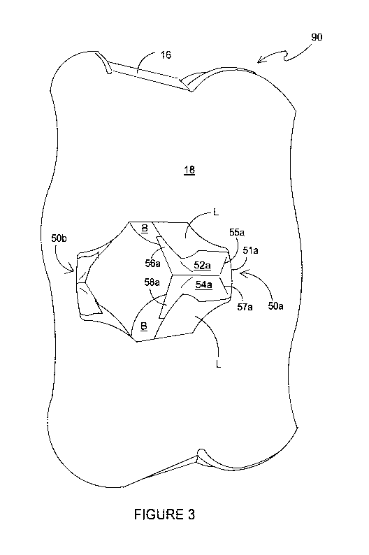
The blank 10 comprises a first retention structure 50a and a second retention
structure 50b.
The first retention structure 50a comprises a first tab 52a/54a hingedly
connected to the top
panel 18 by a fold line 51a. The first tab 52a/54a comprises a center or
longitudinal fold line
53a defining a first part 52a and a second part 54a.
- 9 -
CA 03078236 2020-04-01
WO 2019/074680
PCT/US2018/053126
The second retention structure 50b comprises a second tab 52b/54b hingedly
connected to
the top panel 18 by a fold line 51b. The second tab 52b/54b comprises a center
or longitudinal
fold line 53b defining a first part 52b and a second part 54b.
The blank 10 comprises two pairs of apertures A3, A4, a first pair of
apertures A3, A4 defines
in part the first tab 52a/54a of the first retention structure 50a. Each of
the first pair of apertures
A3, A4 defines a recessed portion in the first tab 52a/54a. Each of the first
pair of apertures
A3, A4 defines at least in part lateral a protrusion or wing portion 56a, 58a
which provides a
shoulder for engaging with an article B disposed in the carton 90.
A second pair of apertures A3, A4 defines in part the second tab 52b/54b of
the second
retention structure 50b. Each of the second pair of apertures A3, A4 defines a
recessed portion
in the second tab 52b/54b. Each of the second pair of apertures A3, A4 defines
at least in part
a lateral protrusion or shoulder 56b, 58b for engaging with an article B
disposed in the carton
90.
The first tab 52a/54a and the second tab 52b/54b may each comprise a pair of
fold lines 55a,
57a, as shown in Figure 3, the pair of fold lines 55a, 57a are divergently
arranged with respect
to each other. The pair of fold lines 55a, 57a may facilitate folding of the
first tab 52a/54a with
respect to the top panel 18, similar fold lines facilitate folding of the
second tab 52b/54b with
respect to the top panel 18.
The pair of fold lines 55a, 57a defines a substantially triangular region of
the first tab 52a/54a
proximate the top panel 18 and may facilitate folding of the first tab 52a/54a
about the fold line
.. 53a such the first part 52a and the second part 54a define a valley or
trough.
Turning to the construction of the carton 90 as illustrated in Figure 2, the
carton 90 can be
formed by a series of sequential folding operations in a straight-line machine
so that the carton
90 is not required to be rotated or inverted to complete its construction. The
folding process is
not limited to that described below and may be altered according to particular
manufacturing
requirements.
A group of articles B is assembled; in the embodiment illustrated in Figure 2
four articles B are
arranged in a 2 x 2 array. The top panel 18 of the blank 10 is disposed above
the group of
articles B to provide a top wall 18 of the carton 90.
-10-
CA 03078236 2020-04-01
WO 2019/074680
PCT/US2018/053126
The first and second bevel panels 16, 20 are folded, with respect to the top
panel 18 about
fold lines 17, 19 respectively, about opposing sides of the group of articles
B so as to be
disposed about upper portions of said articles B. A flange or skirt L of each
article B is received
in a respective one of the second apertures A2 of the top engaging structures
T.
The first and second side walls 14, 22 are folded about the opposing sides of
the group of
articles B. Free edges of the first and second side wall 14,22, defined by the
second apertures
A2, are disposed below the flanges L of the articles B.
Figures 6A and 6B illustrate, from below assembly of the carton 90. Figure 6A
shows the
second side wall 22 before folding about fold line 21. Figure 6B shows the
second side wall
22 after folding about fold line 21.
The recessed portion of the second aperture A2 enables or facilitates folding
of the second
side wall 22 and may provide sufficient clearance for the second side wall 22
to pass the flange
L of the article B.
The recessed portion of the second aperture A2 may also allow the second side
wall 22 to be
folded further about the fold line 21. In embodiments in which the article B
are tapered in
shape, that is to say their width or diameter reduces towards the base, the
recessed portion
of the second aperture A2 may allow a lower region of the second side wall 22
to be brought
closer to the heel of the article B for increased security of the article B
within the carton 90.
The recessed portion receives a portion of an article B.
The recessed portion of the second aperture A2 may also allow a greater
proportion of the
flange L to pass through the second aperture A2.
The engaging edges El, E2 engage with the flange L of the article B received
in the second
aperture and may support or secure the article B as shown in Figure 5B.
The first base panel 12 is folded about the fold line 13 so as to be disposed
adjacent the base
of the group of articles B. The second base panel 24 is then folded about the
fold line 23 so
as to be in at least partial overlapping relationship with the first base
panel 12. The first and
second base panels 12, 24 are secured together. Each of the male tabs M is
displaced
inwardly out of the plane of the second base panel 24. In so doing, each of
the female tabs F
is displaced inwardly creating a corresponding opening in the first base panel
12. The male
-11-
CA 03078236 2020-04-01
WO 2019/074680
PCT/US2018/053126
tabs M are received in respective ones of the openings so as to lock the first
and second base
panels 12, 24 together. In this way, a tubular structure is formed about the
group of articles B.
The assembled carton 90 is shown in Figures 2 to 5A.
Figure 2 illustrates the carton 90, from above, prior to deployment of the
retention structures
50a, 50b. A portion of the top panel 18 of the carton 90 is shown in Figure 3,
the retention
structures 50a, 50b are in a deployed condition. The first and second tabs
52a/54a, 52b/54b
are folded inwardly of the top panel 18. The first and second tabs 52a/54a,
52b/54b are folded
with respect to each other about fold lines 53a, 53b.
A first wing portion 56a of the first tab 52a/54a engages with the flange L of
a first article B. A
second wing portion 58a of the first tab 52a/54a engages with the flange L of
a second article
B adjacent to the first article B.
A first wing portion 56b of the second tab 52b/54b engages with the flange L
of a third article
B. The third article B opposes the first article B. A second wing portion 58b
of the second tab
52b/54b engages with the flange L of a fourth article B adjacent to the third
article B and
opposing the second article B.
Each retention structure 50a, 50b secures or locks a pair of articles B within
the carton 90.
The retention structures 50a, 50b engage with internal side or edges of the
articles B, best
shown in Figure 4.
The angled shape of the first and second tabs 52a/54a, 52b/54b may serve to
push or
encourage the articles B with which it is in engagement outwardly, as
indicated by direction
arrow D1, D2 in Figure 4, in doing so the articles B are securely held in the
top engaging
structures T. In this way the retention structures 50a, 50b may provide a
stabilizer or brace for
the articles B.
The wing portions 56a, 58a, 56b, 58b of the retention structures 50a, 50b
engage or catch
with the undersides, in normal use, of the flanges of the articles. In doing
so the wing portions
56a, 58a, 56b, 58b hold the retention structures 50a, 50b in position between
a pair of articles
B.
The angled shape of the first and second tabs 52a/54a, 52b/54b may inhibit or
prevent the
articles B from unintentionally disengaging from its respective top engaging
structure T.
- 12-
CA 03078236 2020-04-01
WO 2019/074680
PCT/US2018/053126
The opening in the top panel 18 created by folding the retention structures
50a, 50b internally
of the carton 90 may serve as a handle aperture, each of the first and second
tab 52a/54a,
52b/54b may be employed as a finger cushion.
Referring now to Figures 7 to 14B, there is shown additional embodiments of
the present
disclosure. In the second and third illustrated embodiments like numerals
have, where
possible, been used to denote like parts, albeit with the addition of the
prefix "100", "200" to
indicate that these features belong to the second and third embodiments
respectively. The
additional embodiments share many common features with the first embodiment
and therefore
only the differences from the embodiment illustrated in Figures 1 to 6B will
be described in
detail.
Turning to Figure 7, there is illustrated a blank 110 for forming a carton 190
according to a
second embodiment (see Figure 8).
The blank 110 comprises a plurality of main panels 112, 114, 116, 118, 120,
122, 124 for
forming a tubular structure. The plurality of main panels 112, 114, 116, 118,
120, 122, 124
comprises a first base panel 112, a first side panel 114, a first bevel or
corner panel 116, a top
panel 118, a second first bevel or corner 120, a second side panel 122 and a
second base
panel 124. The plurality of panels 112, 114, 116, 118, 120, 122, 124 may be
arranged in a
linear series hinged one to the next by corresponding fold lines 113, 115,
117, 119, 121, 123.
The blank 110 is adapted to accommodate six articles B arranged in a 3x2
matrix or array.
The blank 110 comprises six top engaging structures T.
The blank 110 comprises three retention structures 150a, 150b, 150c struck
from the top panel
118.
A first retention structure 150a comprises a first tab 152a/154a hingedly
connected to the top
panel 118 by a fold line 151a. The first tab 152a/154a comprises a center or
longitudinal fold
line 153a defining a first part 152a and a second part 154a.
The blank 110 comprises three pairs of apertures A3, A4, a first pair of
apertures A3, A4
defines in part the first tab 152a/154a of the first retention structure 150a.
Each of the first pair
of apertures A3, A4 defines a recessed portion in the first tab 152a/154a.
Each of the first pair
of apertures A3, A4 defines at least in part a lateral protrusion or wing
portion 156a, 158a
-13-
CA 03078236 2020-04-01
WO 2019/074680
PCT/US2018/053126
which provides a shoulder for engaging with one or more articles B disposed in
the carton
190.
A second retention structure 150b comprises a second tab 152b/154b similarly
arranged to
the first tab 152a/154a. The second tab 152b/154b is disposed in opposition to
the first tab
152a/154a in a similar arrangement to the first embodiment. The first and
second retention
structures 150a, 150b are disposed in vertical alignment with a void between a
first group of
four adjacent articles B. The four adjacent articles B may be formed from a
pair of articles B
in a central column and a pair of articles B in an endmost column proximate a
first end of the
carton 190.
A third retention structure 150c comprises a third tab 152c/154c similarly
arranged to the first
tab 152a/154a.
The third retention structure 150c is disposed in vertical alignment with a
void between a
second group of four adjacent articles B. The four adjacent articles B of the
second group may
be formed from a pair of articles B in a central column and a pair of articles
B in an endmost
column proximate a second end of the carton 190. The pair of articles B in the
central column
are shared by the first and second groups such that they belong to either
first or second group
of articles.
Optionally, the blank 110 comprises a handle flap or finger cushion 160. The
handle flap 160
comprises a handle tab 162/164 comprising a first part 162 hingedly connected
to a second
part 164 by a fold line 163. The handle flap 160 comprises pair of fold lines
165, 167. The pair
of fold lines 165, 167b are divergently arranged with respect to each other.
The pair of fold
lines 165, 167 may facilitate folding of the handle tab 162/164 with respect
to the top panel
118.
The pair of fold lines 165, 167 defines a substantially triangular region of
the handle tab
162/164 proximate the top panel 118 and may facilitate folding of the handle
tab 162/164 about
the fold line 163 such the first part 162 and the second part 164 define a
valley or trough.
The handle flap 160 is arranged in opposition to the third retention structure
150c.
The handle flap 160 may be employed together with the second retention
structure 150b to
form a carrying handle. A user may engage the handle flap 160 with a thumb or
finger and the
second retention structure 150b with the other of the thumb or finger to grasp
the carton 190
- 14-
CA 03078236 2020-04-01
WO 2019/074680
PCT/US2018/053126
and transport the carton 190 as shown in Figure 8. It will be appreciated that
the user may
carry the carton 190 in other ways by engaging with one or more of the first,
second or third
retention structures 150a, 150b, 150c and/or handle flap 160.
Figure 9A illustrates the third retention structure 150c and the handle flap
160. The third
retention structure 150c is partially folded inwardly, as indicated by
direction arrow D4, into
the interior of the carton 190 and may be folded into a void between a
plurality of articles
disposed with the carton 190.
Figure 9B illustrates the third retention structure 150c in engagement with
each of a pair of
adjacent articles B within the carton 190. The third tab 152c/154c has been
folded inwardly,
as indicated by direction arrow D5, to engage said articles B. A first wing
portion 156c is shown
located below the flange L of one of the pair of articles B. The flange L is
received in a recess
in the side edge of the first part 152c of the third tab 152c/154c. A second
wing portion 158c,
not visible in Figure 9B, is similarly located. Figures 10A, 10B and 11 show
further views of
the retention structures 150a, 150b, 150c in engagement with articles B in the
carton 190.
Turning to Figure 12, there is illustrated a blank 210, for forming a carton
290 according to a
third embodiment (see Figure 13). The blank 210 comprises a plurality of main
panels 212,
214, 218, 222, 224 for forming a tubular structure.
The plurality of main panels 212, 214, 218, 222, 224 comprises a first base
panel 212, a first
side panel 214, a top panel 218, a second side panel 222 and a second base
panel 224. The
plurality of panels 212, 214, 218, 222, 224 may be arranged in a linear series
hinged one to
the next by corresponding fold lines 213, 217, 219, 223.
The blank 210 is adapted to accommodate six articles B arranged in a 3x2
matrix or array.
The blank 210 comprises six top engaging structures T. Each of the top
engaging structures
T is substantially similar in construction and will be described with
reference to a top engaging
structure T provided in the second side panel 222.
Each of the top engaging structures T comprises an opening defined by a cut
line or severable
line 230. The cut line 230 is struck from at least the second side panel 222.
Optionally, the cut
line 230 is curved or arcuate in shape. The cut line 230 interrupts the fold
line 219 between
.. the top panel 218 and the second side panel 222. A pair of further cut
lines 232, 234 may
extend radially outward from the cut line 230. When the second side panel 222
is folded with
-15-
CA 03078236 2020-04-01
WO 2019/074680
PCT/US2018/053126
respect to the top panel 218, about fold line 219, the cut line 230 opens up
to form an opening
which can receive a portion of an article B.
The cut lines 230 each define a protrusion extending from the side edges of
the top panel 218
and integrally formed therewith. The protrusions are struck from material
which would
otherwise form the second side panel 222. In this way protrusions may be
considered to be
struck from one of the first and second side panels 214, 222. The protrusions
each form a
protective top cover for a portion of an article B which is received in the
opening formed by
folding the side panels 214, 222, see Figure 13.
In the third illustrated embodiment, the bevel panels have been omitted, it
will be appreciated
that the blank of Figure 12 could employ bevel panels similar to the previous
illustrated
embodiments. It will also be appreciated that the bevel panel 16, 20; 116,120
of the
embodiments of Figures 1 and 7 could be omitted, such embodiments may employ
the top
engaging structures T of the embodiment of Figure 12.
The first and second side panels 214, 222 comprise optional apertures A3,
which may improve
air flow or ventilation of the carton 290 for example when in cold storage.
The blank 210 comprises four retention structures arranged in pairs and
denoted generally by
references signs 270a, 270b. The retention structures 270a, 270b are struck
from the top
panel 218.
A first pair of retention structures 270a comprises a first tab 272/274 and a
second tab
.. 282/284.
The first tab 272/274 is hingedly connected to the top panel 218 by a fold
line 273 and the
second tab 282/284 is hingedly connected to the top panel 218 by a fold line
283.
The first tab 272/274 comprises a first part 272 hingedly connected to a
second part 274 by a
center or longitudinal fold line 279.
The second tab 282/284 comprises a first part 282 hingedly connected to a
second part 284
by a center or longitudinal fold line 289.
The first tab 272/274 is separated from the second tab 282/284 by a cut line
or severable line
276.
- 16-
CA 03078236 2020-04-01
WO 2019/074680
PCT/US2018/053126
The first tab 272/274 comprises a first wing portion defined by a outline 271
which defines a
shoulder for engaging an article B. The outline 271 is offset from the fold
line 273. The cut line
271 is disposed on a first side of the fold line 273. The first tab 272/274
comprises a second
wing portion defined by a outline 277 which defines a shoulder for engaging an
article B. The
outline 277 is offset from the fold line 273. The cut line 277 is disposed on
a second side of
the fold line 273 which second side opposes the first side.
The offset arrangement of the cut lines 271, 277 with respect to the fold line
273 provides a
recess between each wing portion and the top panel 218 when the first tab
272/274 is folded
.. about fold line 273. Each recess can receive a flange L of an article B so
as to secure the
article B within the carton 290 as shown in Figures 14B and 14B. The side
edges of the first
tab 272/274 are shaped complementary to the articles B.
The second tab 282/284 comprises a first wing portion defined by a outline 281
which defines
a shoulder for engaging an article B. The outline 285 is offset from the fold
line 283. The cut
line 281 is disposed on a first side of the fold line 283. The second tab
282/284 comprises a
second wing portion defined by a outline 287 which defines a shoulder for
engaging an article
B. The outline 287 is offset from the fold line 283. The cut line 287 is
disposed on a second
side of the fold line 283 which second side opposes the first side.
The offset arrangement of the cut lines 281, 287 with respect to the fold line
283 provides a
recess between each wing portion and the top panel 218 when the second tab
282/284 is
folded about fold line 283. Each recess can receive a flange L of an article B
so as to secure
the article B within the carton 290.
The first pair of retention structures 270a are disposed in vertical alignment
with a void
between a first group of four adjacent articles B. The four adjacent articles
B may be formed
from a pair of articles in a central column and a pair of articles in an
endmost column proximate
a first end of the carton 290.
The second pair of retention structures 270b are disposed in vertical
alignment with a void
between a second group of four adjacent articles B. The four adjacent articles
B of the second
group may be formed from a pair of articles in a central column and a pair of
articles in an
endmost column proximate a second end of the carton 290. The pair of articles
B in the central
column are shared by the first and second groups such that they belong to
either first or second
group of articles.
-17-
CA 03078236 2020-04-01
WO 2019/074680
PCT/US2018/053126
The present disclosure provides a carton 90; 190; 290 for packaging articles
B; the carton
comprises a top engaging device 50a, 50b, T; 150a, 150b, 150c, T; 270a, 270b
for flanged
articles, such as flanged cups; the cups may be disconnected or may connected
to each other
via their respective flanges. The carton 90; 190; 290 comprises a plurality of
panels forming
walls of a tubular structure including a top wall 18; 118; 218, a first side
wall 14, 16; 114,116;
214, a base wall 12/24; 112/124; 214/224, and a second side wall 22, 20; 122,
120; 222,
optionally hingedly connected to each other in a linear series. The top
engaging device may
take the form of a stabilizer 52a/54a, 52b/54b; 152a/154a, 152b/154b,
152c/154c; 272/274,
282/284 hingedly connected to the top panel 18; 118; 218 and folded into an
interior of the
carton 90; 190; 290. The stabilizer 52a/54a, 52b/54b; 152a/154a, 152b/154b,
152c/154c;
272/274, 282/284 when folded defines an opening which may form a handle
aperture for
carrying the carton 90; 190; 290. The stabilizer 52a/54a, 52b/54b; 152a/154a,
152b/154b,
152c/154c; 272/274, 282/284 may provide a finger cushion. The stabilizer
52a/54a, 52b/54b;
152a/154a, 152b/154b, 152c/154c; 272/274, 282/284 may be formed from a first
part 52a,
52b; 152a, 152b, 152c; 272, 282 and a second part 54a, 54b; 154a, 154b, 154c;
274, 284
hingedly connected to each other, the first and second parts 52a,54a, 52b,54b;
152a,154a,
152b,154b, 152c,154c; 272,274, 282,284 form hooking panels each having
engaging edges
for engaging undersides of flanges L of a pair of adjacent flanged articles B.
The stabilizer
52a/54a, 52b/54b; 152a/154a, 152b/154b, 152c/154c; 272/274, 282/284 may be
substantially
"T" shaped.
The top engaging device may take the form of an article retainer T comprising
an article
retaining aperture A2 struck at least from one of the side walls 14, 16, 22,
20; 114,116,122,
120; 214, 222. The article retaining aperture A2 is defined at least by a
lower edge which
comprises a pair of engaging edges El, E2 for engaging the flange L of a
flanged article B
and a recess Cl extending between the engaging edges for receiving part of the
flanged article
B.
It can be appreciated that various changes may be made within the scope of the
present
invention. For example, the size and shape of the panels and apertures may be
adjusted to
accommodate articles of differing size or shape.
It will be recognized that as used herein, directional references such as
"top", "bottom", "base",
"front", "back, "end", "side", "inner, "outer, "upper" and "lower" do not
necessarily limit the
respective panels to such orientation, but may merely serve to distinguish
these panels from
one another.
-18-
CA 03078236 2020-04-01
WO 2019/074680
PCT/US2018/053126
As used herein, the terms "hinged connection" and "fold line" refer to all
manner of lines that
define hinge features of the blank, facilitate folding portions of the blank
with respect to one
another, or otherwise indicate optimal panel folding locations for the blank.
Any reference to
"hinged connection" should not be construed as necessarily referring to a
single fold line only;
indeed, a hinged connection can be formed from two or more fold lines wherein
each of the
two or more fold lines may be either straight/linear or curved/curvilinear in
shape. When linear
fold lines form a hinged connection, they may be disposed parallel with each
other or be
slightly angled with respect to each other. When curvilinear fold lines form a
hinged
connection, they may intersect each other to define a shaped panel within the
area surrounded
by the curvilinear fold lines. A typical example of such a hinged connection
may comprise a
pair of arched or arcuate fold lines intersecting at two points such that they
define an elliptical
panel therebetween. A hinged connection may be formed from one or more linear
fold lines
and one or more curvilinear fold lines. A typical example of such a hinged
connection may
comprise a combination of a linear fold line and an arched or arcuate fold
line which intersect
at two points such that they define a half moon-shaped panel therebetween.
As used herein, the term "fold line" may refer to one of the following: a
scored line, an
embossed line, a debossed line, a line of perforations, a line of short slits,
a line of half-cuts,
a single half-cut, an interrupted outline, a line of aligned slits, a line of
scores and any
combination of the aforesaid options.
It should be understood that hinged connections and fold lines can each
include elements that
are formed in the substrate of the blank including perforations, a line of
perforations, a line of
short slits, a line of half-cuts, a single half-cut, a outline, an interrupted
outline, slits, scores,
any combination thereof, and the like. The elements can be dimensioned and
arranged to
provide the desired functionality. For example, a line of perforations can be
dimensioned or
designed with degrees of weakness to define a fold line and/or a severance
line. The line of
perforations can be designed to facilitate folding and resist breaking, to
facilitate folding and
facilitate breaking with more effort, or to facilitate breaking with little
effort.
The phrase "in registry with" as used herein refers to the alignment of two or
more elements
in an erected carton, such as an aperture formed in a first of two overlapping
panels and a
second aperture formed in a second of two overlapping panels. Those elements
in registry
with each other may be aligned with each other in the direction of the
thickness of the
overlapping panels. For example, when an aperture in a first panel is "in
registry with" a second
aperture in a second panel that is placed in an overlapping arrangement with
the first panel,
an edge of the aperture may extend along at least a portion of an edge of the
second aperture
-19-
CA 03078236 2020-04-01
WO 2019/074680
PCT/US2018/053126
and may be aligned, in the direction of the thickness of the first and second
panels, with the
second aperture.
- 20 -