Note : Les descriptions sont présentées dans la langue officielle dans laquelle elles ont été soumises.
CA 03078854 2020-04-09
H83259I9CA
Arrangement comprising two switch cabinet racks interconnected by means of a
having
connector
The invention relates to an arrangement, which comprises two switch cabinet
racks
interconnected by means of a baying connector, the switch cabinet racks each
having a
profile web, which lie in a first common plane and by means of which the
switch cabinet
racks adjoin each other. The switch cabinet racks each have a mounting side
which lie in a
second common plane and face an interior space of the interconnected switch
cabinet racks
each, the first and the second plane. extending parallel to one another and
being spaced apart
from one another. Such an arrangement is known from DE 10 2014 101 401 Al.
The arrangements known from prior art have the disadvantage that the baying
connector is
arranged outside the sealing area of the bayed switch cabinet racks and is
therefore
accessible from the outside of the arrangement and thus not protected against
sabotage.
Furthermore, baying connectors are known which are mounted from the inside of
the switch
cabinet racks, but then extend into the installation clearance of the switch
cabinet
arrangement and thus render the valuable installation space inside the switch
cabinet racks
partially unusable.
It is therefore the object of the invention to further develop an arrangement
of the kind
described above in such a way that it is sabotage-proof on the one hand and
space-saving on
the other.
This object is achieved by an arrangement having the features of claim 1. The
dependent
claims each relate to advantageous embodiments of the invention.
Accordingly, it is provided that the baying connector is completely arranged
between the first
and the second plane. This achieves that the baying connector is both facing
the interior of
the switch cabinet racks and is otherwise still arranged behind a rearmost
mounting plane of
the switch cabinet racks, which lies in the second common plane of the
mounting sides of the
switch cabinet racks, and thus does not restrict the installation space inside
the switch
cabinet racks.
Date Recue/Date Received 2020-04-09
CA 03078854 2020-04-09
H8325919CA
The baying connector may have a body with opposite contact sides, with which
it rests
against a further profile side each, which extends between the first and
second planes and
perpendicular to them. In particular, it may be provided that the further
profile side
connects the mounting side with the profile web. The mounting side can be bent
from the
further profile side by a 90' bent edge. Likewise, the profile web can be bent
from the other
profile side by means of a 900 bent edge. In particular, the mounting side and
the profile web
can be bent in opposite directions from the further profile side. The profile
web and the
mounting side can be spaced apart from each other by a dimension of the
further profile side
that extends perpendicular to the profile web and the mounting side. The other
side of the
profile can have a system perforation consisting of regularly spaced fastening
apertures. In
particular, the switch cabinet rack can be made of circumferential identical
profiles. A
suitable, switch cabinet rack is known from DE 10 2015 121 192 Al.
At least one screw passage can extend over the entire length of the baying
connector between
the contact sides and through the contact sides. In particular, it can be
provided that the
screw channel is formed continuously over the entire length between the
contact sides, i.e.
without interruptions, in order to achieve precise guidance of a screw bolt.
The baying connector may also have at least one centering pin extending from
at least one of
the contact sides and perpendicular to it. The centering pin can have, in
particular on its
outer circumference, a contour which corresponds to the contour of an opening
or fastening
aperture through the further profile side of the switch cabinet rack. In
particular., the
centering pin can be accommodated form-fittingly in the opening or fastening
aperture. The
centering pin can be positioned in relation to the at least one screw passage
in such a way
that a defined alignment of the screw passages of the baying connector with
respect to
further openings in the further profile side is achieved, so that the screw
passages are aligned
with the openings for the insertion of a screw bolt.
At least one latching projection can extend from at least one of the contact
sides through a
fastening aperture in one of the further profile sides and fix the baying
connector to the
further profile side, in particular latch it. The fastening apertures can be
part of a system
perforation of the further profile side. The system perforation can have
fastening apertures
which extend along a straight line with a fixed grid dimension. Several
latching projections
may extend from at least one of the contact sides, the latching projections
having a distance
from each other which corresponds to an integral multiple of the grid
dimension. A suitable
system perforation is described in DE 10 2015 121 192 Ai.
2
Date Recue/Date Received 2020-04-09
CA 03078854 2020-04-09
148325919CA
The latching projection may have a sliding surface which extends from one of
the contact
sides and perpendicularly to it and which is arranged opposite a hook of the
latching
projection, the sliding surface bearing form-fittingly against an edge of the
fastening
aperture through which the latching projection extends.
At least one screw passage may extend over the entire length of the baying
connector
between the contact sides and through the contact sides, the at least one
screw passage being
aligned with the at least one latching projection and continued through the
latching
Projection.
A screw bolt can be passed through a closed profile section of the switch
cabinet rack from an
outer profile side of the switch cabinet rack, which is arranged parallel to
and spaced apart
from the further profile side. -For this purpose, the switch cabinet rack can
again have a
geometry as known from 1)E 10 2015 121 192 At
The screw bolt can enter the closed profile section via an outer profile side
and exit the closed
profile section via the further profile side and enter the baying connector
via one of two
opposite contact sides of the baying connector.
In this case, the screw bolt can have an external thread at least in an end
section facing away
from the screw bolt head, with which it is screwed into the at least one screw
passage, which
has an internal thread.
The screw bolt can bear against the outer profile side with a screw bolt head.
The baying connector may have a mounting side with a row of holes of
equidistantly spaced
fastening apertures lying in or extending through the second common plane of
the mounting
side.
In that case, the fastening apertures can have a distance to each other which
corresponds to
the grid dimension of a system perforation of the switch cabinet rack.
The fastening apertures of the baying connector may be arranged along a linear
row of holes
and may be formed identical to fastening apertures of the system perforation,
wherein the
fastening apertures of the baying connector and at least one identical
fastening aperture of
the system perforation are arranged along a straight line, a distance between
each of the
3
Date Recue/Date Received 2020-04-09
CA 03078854 2020-04-09
1-183259 I 9CA
fastening apertures of the baying connector and the at least one fastening
aperture of the
system perforation being an integer multiple of the grid dimension.
The profile webs can adjoin each other under formation of a sealing gap and
can be formed
as identical sealing webs widening towards their free end, wherein a push-on
seal is pushed
onto one of the sealing webs, which push-on seal seals the sealing gap fluid-
tight.
The contact sides of the baying connector can have a spacing that is slightly
greater than the
sum of the length of the profile webs, wherein the push-on seal has a defined
compression
when the further profile sides abut the opposite contact sides of the baying
connector.
For fastening the racks to each other, the centering pin can be used to
position the baying
connector on a first of the two racks to be connected to each other, e,g. on a
first vertical
profile of the rack, so that two threaded bolts inserted via the outer profile
side and formed
as shaft screws can be screwed into the screw passages of the baying
connector. Thus, the
baying connector is fixed to the first of the two racks.
Then, the second of the two racks can be lined up with the first rack by
pushing the two latching
projections of the baying connector into a fastening aperture each.
When the latching projections lengthen the screw passages, they have the
function of an
insertion aid for further screw bolts, which are inserted via the outer
profile side of the second
rack. The latching projections can extend into the closed profile section by a
dimension for this
purpose. This dimension can be adjusted according to the distance between the
outer profile
side and the further profile side in such a way that sufficient guidance of
the screw bolt is
ensured for easy fastening of the second rack to the baying connector.
The centering pin can have a length perpendicular to the contact side from
which it extends,
which is dimensioned in such a way that the baying connector can also be
retrofitted, i.e. when
the racks are close to each other in the baying situation, the other baying
connectors that may
be present are pre-assembled via their screw bolts, but the bolts have not yet
been tightened,
so that the sealing element is not yet compressed and there is therefore
sufficient space for
inserting the baying connector between the further profile sides facing each
other.
This can be further facilitated by the latching projections being form-
fittingly accommodated
in the fastening apertures in only one dimension. In the dimension parallel to
the fastening
apertures, the latching projections can be smaller than the fastening
apertures, so that the
4
Date Recue/Date Received 2020-04-09
CA 03078854 2020-04-09
1-18325919CA
latching projections can be rotated into the fastening apertures by means of a
rotary movement
in the plane perpendicular to the plane of the fastening apertures.
Adjacent to its bolt head, the shaft of the fastening bolt may have a diameter
corresponding
to a distance between opposite sides of the fastening aperture in the outer
profile side via
which the fastening bolt is inserted into the rack. This widened shaft section
does not extend
to the further profile side, but only serves as a support for easier
positioning of the fastening
bolt in the fastening aperture, which can be a rectangular hole, on the outer
profile side.
Further details of the invention are explained with the following figures.
These show:
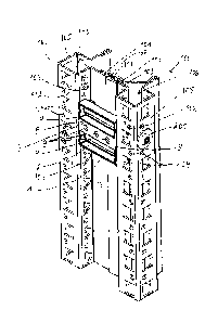
Figure i in perspective view, a view of the inside of an arrangement
according to the
invention according to an embodiment of the invention; and
Figure 2 a detailed view of the baying connector according to Figure 1.
In Figures i and 2 an embodiment of the arrangement according to the invention
is shown.
In this case, two switch cabinet racks too are interconnected at their side
facing the interim.
of the switch cabinet racks 100, i.e. towards the installation space of the
switch cabinet racks
100, by means of a baying connector 1. The switch cabinet racks 100 adjoin
each other via
opposing profile webs 101, which are arranged in a first common plane. The
profile webs iot
are formed as sealing webs with a sealing element 8 arranged between them, so
that the first
common plane forms. a sealing plane of the arrangement. Consequently, the
baying
connector 1 is protected from external environmental influences and access via
the sealing
plane.
Baying connector 1 is arranged particularly between the previously described
sealing plane
and a second common plane of the mounting sides 102 of the switch cabinet
racks in a space-
saving manner. The second common plane, which is defined by the mounting sides
102, is
precisely the rearmost mounting plane of the switch cabinet racks too. Since
the baying
connector i is located completely behind the mounting plane formed by the
second common
plane or its front side is located exactly in the second common plane,
respectively , the
haying connector 1 is arranged in a space-saving manner and in particular can
also be
superposed without the component superposing the baying connector 1 colliding
with the
baying connector .1.
Date Recue/Date Received 2020-04-09
CA 03078854 2020-04-09
148325919CA
The switch cabinet rack 100 is formed according to the switch cabinet rack
known from DE
2015 121 192 Al. Each of the interconnected switch cabinet racks 100 has a
further profile
side 103, which connects the respective mounting side 102 with the respective
profile web
101 via a 900 bent edge. Opposite the further profile side 103, an outer
profile side 105 is bent
from the mounting side 102 via a further 90" bent edge from the mounting side
102. Via the
outer profile side 105, a screw bolt 200 is passed through a closed profile
section 106 of the
switch cabinet rack too up to where the bolt 200 leaves the closed profile
section io6 via the
further profile side 103 and enters there directly with its free end into one
of the screw
passages 4 of the baying connector 1. The screw passages 4 have an internal
thread so that a
force-fit connection can be made between the switch cabinet rack 100 and
baying connector
1. A defined compression of the push-on seal 108 is achieved with the screw
connection in
such a way that the length of the baying connector 1, i.e. the distance
between the contact
sides 3 of the baying connector i is dimensioned such that a defined sealing
gap 107 is
formed between the free ends of the sealing webs 103 when the baying
connectort rests via
its opposite contact side 3 against the further profile sides 103 of the
switch cabinet racks
100.
Baying connectorl also has a mounting plane E with a system perforation of
circular
fastening apertures 9 spaced at a grid dimension. The fastening apertures 9 of
the baying
- connector 1 are arranged along a straight line and have a distance to
further, identical
fastening apertures 104 of the mounting sides 102 of the switch cabinet racks
too, which lie
on the same straight line, which corresponds to an integral multiple of the
grid dimension.
Expediently, the grid dimension of the fastening apertures 9 of the baying
connector 1 has
precisely a value that corresponds to the grid dimension of the fastening
apertures 104 of the
switch cabinet racks 100, so that the grid dimension of the switch cabinet
racks um is also
maintained across the mounting plane E of the baying connector 1 and thus
across the
adjacent switch cabinet racks loo. This has the advantage that installation
components
whose fastening means are designed to be fixed to a system perforation of
switch cabinet
racks too can also be mounted across adjacent switch cabinet racks 100. For
example, a
switch cabinet light may extend between adjacent switch cabinet racks too of
the
arrangement and be fastened with a first of its opposite ends in a first of
the switch cabinet
racks 100 and with a second of its opposite ends in a second of the switch
cabinet racks 100
adjacent to the first switch cabinet rack 100 and fixed by means of the baying
connector 1.
As can be.seen in Figure 2, the baying connector 1 essentially consists of a
body 2 which has
opposite contact sides 3. Screw passages 4 extend perpendicularly to the
contact sides 3 over
6
Date Recue/Date Received 2020-04-09
CA 03078854 2020-04-09
H83259I9CA
the entire distance between the contact sides 3, so that continuous guidance
of a screw bolt
200 (see Figure 1.) between the contact sides 3 is ensured. Latching
projections 6.extend from
the contact sides 3 and are aligned with the screw passages 4, so that the
screw passages 4
continue through the latching projections 6. On opposite sides, which extend
perpendicularly to the respective contact side 3, the latching projections 6
have a sliding
surface 7 and a hook 8 opposite this sliding surface. Hook 8 is configured to
engage behind a
fastening aperture 104 (see Figure].) in the edge area in a mounted state of
baying connector
1, thus simplifying the mounting of baying connector 1.
On the further contact side 3, which is arranged opposite the contact side 3
with the latching
projections 6, a centering pin 5 is formed, which extends perpendicularly to
the further
contact side 3 and has a contour on its outer circumference which corresponds
to an inner
contour of a.fastening aperture 104 of the further profile side 103 (see
Figure 1). The
centering pin 5 is used in particular for pre-aligning the screw passages 4 in
relation to the
further fastening apertures 104 in the further profile side 103.
When fastening the racks too to each other, the centering pin 5 can be used to
position the
baying connector i on a first of the two racks 100 to be connected to each
other, for example
on a first vertical profile of the rack 100, so that two threaded bolts 200
inserted via the outer
profile side 105 and formed as shaft screws can be screwed into the screw
passages 4 of the
baying connector 1, so that the baying connector 1 is fixed to the first of
the two racks too.
The second of the two racks too can then be lined up with the first rack 100
by pushing the
two latching projections 6 of the baying connector 1 into a fastening aperture
104 each. Since
the latching projections 6 lengthen the screw passages 4, they have the
function of an insertion
aid for further screw bolts, which are inserted via the outer profile side 105
of the second rack
100. For this purpose, the latching projections extend by a dimension into the
closed profile
section, wherein the dimension is adjusted according to the distance between
the outer profile
side 105 and the further profile side 103 in such a way that sufficient
guidance of the screw
bolt is ensured for easy fastening of the second rack 100 to the baying
connector 1.
The centering pin 5 has a length perpendicular to the contact side 3 from
which it extends,
which is dimensioned so that baying connector 1 can also be retrofitted when
the racks 100
are close to each other in the baying situation, but the other baying
connectors 1, which may
be present, are pre-assembled via their bolts 200, but these bolts are not yet
tightened, so that
the sealing element 108 is not yet compressed and there is therefore
sufficient space for
7
Date Recue/Date Received 2020-04-09
CA 03078854 2020-04-09
H8325919cA
inserting the baying connector between the further profile sides 103 facing
each other. This is
further facilitated by the latching projections 6 being form-fittingly
accommodated in the
fastening apertures 104 in only one dimension. In the dimension parallel to
the fastening
apertures 104, the latching projections 6 are smaller than the fastening
apertures 104, so that
the latching projections 6 can be rotated into the fastening apertures 104 via
a rotary
movement in the plane perpendicular to the plane of the fastening apertures
104.
Adjacent to its bolt head, the shaft of the fastening bolt 200 may have a
diameter
corresponding to a distance between opposite sides of the fastening aperture
104 in the outer
profile side 105 via which the fastening bolt 200 is inserted into the rack.
This widened shaft
section does not extend to the further profile side 103, but only serves as a
support in the
rectangular hole of the outer profile side 105 for easier positioning of the
fastening bolt 200.
The features of the invention disclosed in the above description, drawings and
claims may be
essential for the realization of the invention either individually or in any
combination.
8
Date Recue/Date Received 2020-04-09
CA 03078854 2020-04-09
I-18325919CA
List of reference numerals
baying connector
body
3 contact side
4 screw passage
centering pin
6 latching projection
7 sliding surface
8 hook
9 fastening aperture
100 switch cabinet rack
101 profile web/sealing web
102 mounting side
103 further profile side
104 fastening aperture
105 outer profile side
106 closed profile section
107 sealing gap
108 push-on seal
200 screw bolt
mounting plane
9
Date Recue/Date Received 2020-04-09