Note : Les descriptions sont présentées dans la langue officielle dans laquelle elles ont été soumises.
CA 03079191 2020-04-14
WO 2019/079727 PCT/US2018/056722
POLYMERIC CELL CULTURING SURFACE HAVING HIGH CELL ADHESION
BACKGROUND
[0001] The technology relates generally to a surface, or surface
modification of a plastic
substrate (sometimes referred to in this disclosure as a contact surface),
being hydrophilic, or
making the surface hydrophilic and enhancing cell adhesion to the surface.
More particularly, the
technology relates to a plastic substrate, e.g. a medical device or item of
laboratory ware, with a
treated surface used for cell culture and cell growth due to its enhanced cell
adhesion. Such
medical devices include, but are not limited to cell culture vessels and
roller bottles.
[0002] Although some cells grow in suspension (e.g. 3D sphere culture
suspension), such as
hematopoietic cell lines and transformed cells, most other cells grow in favor
of high surface
binding (e.g. monolayer growth); that is, they require surface attachment to
proliferate.
Historically, glass was used as the growth surface since it has superior
optical qualities, is
hydrophilic and naturally charged which are favored to promote cell growth.
Disposable plastic,
especially polystyrene is now most commonly used for cell culture growth.
Polystyrene culture
vessels are of good optical quality.
[0003] However, since most plastics are hydrophobic and unsuitable for cell
growth, their
surfaces need to be treated or coated.
[0004] In cell growth vessels, it is desirable to enhance cell adsorption
and cell binding to the
plastic ware used with biological substances. Surfaces of common laboratory
ware components
made of polymeric plastic are hydrophobic and usually don't have good cell
adhesion. It is thus a
desire to provide surfaces for plastic laboratory ware and other articles that
contact biological
substances with higher hydrophilicity and thereby improved cell adhesion.
[0005] The present invention also relates to the technical field of
fabrication of coated vessels
for conducting chemical, biochemical, medical, and/or biological uses. These
methods and systems
are essential in a variety of applications including medical diagnostics,
medical treatment,
environmental monitoring, manufacturing quality control, drug discovery, and
scientific research.
[0006] This invention generally relates to fabrication of cell growth and
cell culture vessels
and plastic lab ware. This invention also relates to producing a hydrophilic
surface by plasma
1
CA 03079191 2020-04-14
WO 2019/079727 PCT/US2018/056722
treatment. This invention further relates to generation of a hydrophilic
surface with enhanced cell
adhesion and thereby an improved cell culture and cell growth.
[0007] Traditionally glassware presents a hydrophilic surface and therefore
was used, and
continues to be used for cell culture and cell growth. However glassware is
readily breakable, very
expensive, prone to particulate problems, yields heavy metal extractables, and
can cause adverse
effect on cell growth and/or aggregation of proteins and other biologics.
[0008] Some of these problems can be addressed by substituting injection
molded plastic ware
for glassware. In particular, plastic ware is preferred in the biologics area,
such as areas of
medicine, medical research, drug discovery, and scientific research, due to
the large number of
issues with glassware. Plastic ware addresses some of the problems with
glassware, but plastic
ware creates certain problems as well. Plastic ware contains
extractables/leachables, preventing
the use of plastic ware or making it undesirable for many types of laboratory
in vitro and analytical
testing. Plastic ware presents a hydrophobic surface which usually gives low
cell adhesion. High
cell adhesion is considered to enhance cell growth. These issues limit the use
of plastic ware for
cell culture vessels and roller bottles.
[0009] Roller bottles are used as cell culture vessels in a wide variety of
applications. Roller
bottles are often made from polystyrene (PS) or polyethylene terephthalate
(PET). These materials
present superior optical clarity, high stability, reduced breakage and many
other advantages.
[0010] The relatively large contacting surface of a roller bottle enhances
cell adhesion, thereby
improving cell growth. To expand the contacting surface, some roller bottles
are designed with
circumferential, axial, or other ribs on the body, which can multiply the
growth surface.
[0011] To generate a hydrophilic surface that is beneficial for cell
growth, some hydrophilic
coatings, including polyethylene glycol (PEG) and zwitterion polymeric
coatings are being used
which provide good cell adhesion. Many of these polymeric coatings are not
covalently bound to
the article surface and have potential to move (dissolve, disperse) into the
fluid payload, causing
interference with cell growth or testing, limiting their utility. Polymeric
coatings that are
covalently attached to the article surface would not have the potential to
move (dissolve, disperse)
into the fluid payload, eliminating this source of interference with cell
growth. Further, covalently
bound polymeric coating would prevent movement of the polymeric surface
coating, thereby
preventing undesired exposure of the article surface.
2
CA 03079191 2020-04-14
WO 2019/079727 PCT/US2018/056722
[0012] There is therefore a need for hydrophilic coatings/treatments for the
surface of plastic
laboratory ware such as cell culture vesselsand roller bottles, that will
enhance the cell adhesion
to the surface of the plastic. Likewise, there is a need for covalently bound
polymeric
coatings/treatments for the surface of plastic laboratory ware such as cell
culture vesselsand roller
bottles that will prevent movement of the polymeric surface coating thereby
preventing undesired
particulate interference and exposure of the plastic surface.
SUMMARY OF THE INVENTION
[0013] An aspect of the invention is a method carried out, in general, by
providing a polymeric
substrate including an initial contact surface, contacting the initial contact
surface with a process
gas, and introducing radio frequency electrical power in the process gas,
forming a treated contact
surface that has improved cell recovery compared to an untreated contact
surface.
[0014] The polymeric substrate includes, in addition to the initial contact
surface, an interior
portion adjacent to the initial contact surface.
[0015] The process gas optionally can be nitrogen gas, oxygen gas, or a
heterogeneous gas that
contains nitrogen atoms, oxygen atoms, or a combination of nitrogen and oxygen
atoms, as well
as other kinds of atoms, for example noble gases. Non-limiting examples of
suitable process gas
include oxygen gas, nitrogen gas, nitrous oxide gas, or a combination of any
two or more of these.
[0016] Optionally, the radio frequency electrical power is introduced in
the process gas
adjacent to the initial contact surface to generate plasma adjacent to the
initial contact surface. As
a result, a treated polymeric substrate is formed having a treated contact
surface.
[0017] The process optionally improves cell recovery of a chicken embryo
cell culture from
the treated contact surface, relative to the initial contact surface,
optionally resulting in cell
recovery from the treated contact surface of at least 140% of the cells
provided to the treated
contact surface at the beginning of the cell recovery test.
3
CA 03079191 2020-04-14
WO 2019/079727 PCT/US2018/056722
BRIEF DESCRIPTION OF DRAWING FIGURES
[0018] In the drawings,
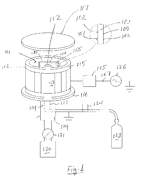
[0019] Fig. 1 is a schematic view of plasma treatment apparatus useful for
carrying out any
embodiment of the invention.
[0020] Fig. 2 is a view similar to Fig. 1 showing plasma treatment
apparatus for treating three
vessels simultaneously.
[0021] Fig. 3 is a schematic sectional view of the apparatus of Fig. 1,
showing internal details
of the apparatus and an additional feature for equalizing pressure inside and
outside of a vessel
being treated.
[0022] Fig. 4 shows a perspective view of a CELLTREATTm roller bottle.
[0023] Fig. 5 shows a photographic view similar to Fig. 4 of a commercial
roller bottle having
multiple circumferential ribs inside and outside its wall, expanding the
surface area for cell
attachment.
[0024] Fig. 6 shows the CELLTREATTm roller bottle of Fig. 5 as referred to
in Example 2 of
this specification, identifying relevant parts of the bottle.
[0025] Figs. 7A and 7B show two examples of aseptic caps which can be used
to close the
vessel of the current invention. Fig. 7A shows a Corning aseptic transfer cap
and Fig. 7B shows
a Sartorius MYCAP closure.
[0026] The following reference characters are used in the drawings:
101 polymeric substrate
102 contact surface
103 interior portion (adjacent to the contact surface)
104 process gas
105 vessel
106 wall (of 105)
107 inner surface (of 106)
108 lumen (of 105)
109 outer surface (of 106)
110 ribs
111 gas inlet conduit
112 outlet (of 111)
4
CA 03079191 2020-04-14
WO 2019/079727 PCT/US2018/056722
113 external applicator
114 internal applicator
115 ceramic chamber
116 aluminum bottom
117 aluminum lid
118 pumping port
119 vacuum conduit
120 vacuum pump
121 Valve
122 processing area
123 gas system
124 mass flow controller
125 matching network
126 power supply
127 coaxial cable
128 vacuum bypass line
129 valve (of 128)
[0027] Like reference characters indicate corresponding parts.
DETAILED DESCRIPTION
[0028] The present disclosure is directed to a process for making a roller
bottle or other lab ware
or substrate having a contact surface that is hydrophilic and has higher cell
adhesion than an
untreated surface or biological coating treated surface.
[0029] Optionally, when the substrate of this invention is used for cell
growth, the cells are
harvested or recovered after the growth process is complete. The recovery rate
optionally is higher
than for a biological coating treated, otherwise identical substrate. The
recovery rate optionally is
higher than for a Corning Cellbind substrate.
[0030] Optionally, if the substrate is embodied as a vessel, the vessel
further comprises a closure.
The closure can be of any kind. For example, the closure can be any stopper,
cap, lid, top, cork or
any combination of them. For example, a plastic or elastomer stopper can be
inserted into a cap
to form a closure.
[0031] Cell growth requires an aseptic environment. Frequent opening and
closing the cap of the
cell culture/growth vessel is one of the sources of contamination. Optionally
cell culture/growth
CA 03079191 2020-04-14
WO 2019/079727 PCT/US2018/056722
vessels (e.g. roller bottles) can be closed with an aseptic transfer cap to
prevent the contamination
due to opening and closing the cap during media feeding, inoculation, sample
addition/collection,
transferring, etc. Optionally, the closure is suitable for an aseptic process,
optionally at high
temperature, low temperature, autoclaving, irradiation or any other unusual
conditions. For
example, the closure can be an aseptic transfer cap with other accessories to
eliminate the need to
open the cap during the cell culture/growth process. Optionally, the closure
can be a corning
aseptic transfer cap. Optionally, the closure can be a Sartorius MYCAP
closure. The MYCAP
closure comprises a silicone elastomer dispensed into a cap. The cap is
assembled by inserting a
tubing and a gas exchange cartridge into preformed holes located on the cap.
[0032] Optionally, the method comprises the steps of (a) providing a
substrate, for example a
vessel, having a contact surface; (b) drawing a vacuum adjacent to the contact
surface; (c)
providing a gas comprising 02, optionally containing nitrogen, in the vicinity
of the contact
surface; and (d) generating a plasma from the gas, thus forming a treated
contact surface. The
formed contact surface is a high cell binding surface.
[0033] Optionally, if the substrate is a roller bottle or other vessel, in
step (c), the gas is optionally
introduced into the vessel through a gas inlet inserted into the vessel (as
illustrated in Fig. XX.
Optionally in this embodiment, RF is used to generate the plasma.
[0034] Surprisingly, it was found that RF power combined with use of a gas
inlet introducing the
gas mixture into a vessel affords great advantages in enhancing the results in
cell growth
experiments. The results are better than uncoated otherwise identical surfaces
and also better than
a Corning Cellbind treated surface. Not limited by the theory, when using RF
power to treat a
vessel without a gas inlet inserted into the vessel to deliver the gas
mixture, less reactive functional
groups may be generated on the surface, thus a less desired treatment may be
obtained. Using a
gas inlet inserted into the vessel to deliver the gas mixture helps generate
more reactive functional
groups on the surface, thus improving surface activation and surface
uniformity to achieve better
cell adhesion/cell growth results.
[0035] There are several advantages for using a RF power source versus a
microwave source:
Since RF operates at a lower power, there is less heating of the
substrate/vessel. Because the focus
of the present invention is a plasma surface treatment of plastic substrates,
lower processing
temperatures are desired to prevent melting/distortion of the substrate. The
higher frequency
6
CA 03079191 2020-04-14
WO 2019/079727 PCT/US2018/056722
microwave can also cause off-gassing of volatile substances like residual
water, oligomers and
other materials in the plastic substrate. This off-gassing can interfere with
the treatment.
[0036] The term "contact surface" indicates a surface that is in a position to
come in contact with
a sample or other material, and has surface properties determining its
interaction with the sample
or other material with which it comes into contact. Some examples of contact
surfaces are part or
all of an interior surface of a vessel (for example, bounding a vessel lumen)
or an exterior surface
of a vessel, sheet, block, or other object. Optionally, the contact surface is
made of the same
material as the interior portion before the contact surface is treated with
plasma.
[0037] The term "interior portion" indicates a portion of a bulk article or
coating that is not a
contact surface, but instead forms part of the interior of the bulk article or
coating. In embodiments
in which a contact surface of a substrate is treated to modify its properties,
the interior portion of
the substrate includes any portion that is not modified by the treatment.
[0038] "Plasma," as referenced in any embodiment, has its conventional meaning
in physics of
one of the four fundamental states of matter, characterized by extensive
ionization of its constituent
particles, a generally gaseous form, and incandescence (i.e. it produces a
glow discharge, meaning
that it emits light).
[0039] A treated contact surface is defined for all embodiments as a contact
surface that has been
plasma treated as described in this specification, and that exhibits enhanced
cell growth as a result
of such treatment.
[0040] The term "vessel" as used throughout this specification may be any type
of article that is
adapted to contain or convey a liquid, a gas, a solid, or any two or more of
these. One example of
a vessel is an article with at least one opening (e.g., one, two or more,
depending on the application)
and a wall including an interior contact surface.
[0041] Referring to Figs. 1-3, the present method can be carried out, in
general, by providing
a polymeric substrate 101 including an initial contact surface 102, contacting
the initial contact
surface 102 with a process gas 104 (shown as the gas source in Fig. 1, and as
the gas in a vessel in
Figs. 1 and 3), and introducing radio frequency electrical power in the
process gas 104, forming a
treated contact surface 102 that has improved cell recovery compared to an
untreated contact
surface 102.
7
CA 03079191 2020-04-14
WO 2019/079727 PCT/US2018/056722
[0042] Optionally in any embodiment, the polymeric substrate 101 includes,
in addition to the
initial contact surface 102, an interior portion 103 adjacent to the initial
contact surface 102.
[0043] Optionally in any embodiment, the process gas 104 can be nitrogen
gas, oxygen gas,
or a heterogeneous gas that contains nitrogen atoms, oxygen atoms, or a
combination of nitrogen
and oxygen atoms, as well as other kinds of atoms. Non-limiting examples of
suitable process
gases 104 include oxygen gas, nitrogen gas, nitrous oxide gas, or a
combination of any two or
more of these. Optionally, the process gas 104 can include a carrier gas, for
example a noble gas,
for example helium, neon, argon, krypton, or xenon or a mixture of any two or
more of these.
[0044] Optionally in any embodiment, the radio frequency electrical power
is introduced in
the process gas 104 adjacent to the initial contact surface 102 to generate
plasma adjacent to the
initial contact surface 102. As a result, a treated polymeric substrate 101 is
formed having a treated
contact surface 102.
[0045] Optionally in any embodiment, the x-ray photoelectron spectroscopy
XPS atomic
composition of the treated contact surface 102 is:
= from 10% to 25% oxygen, from 0 to 5% nitrogen, and from 70% to 90%
carbon;
= optionally from 15% to 24% oxygen, from 0.1% to 5% nitrogen, and from 70%
to
80% carbon;
= optionally from 20% to 24% oxygen, from 0.1% to 1% nitrogen, and from 70%
to
79% carbon.
[0046] Optionally in any embodiment, the XPS atomic composition of the
interior portion 103
of the treated polymeric substrate 101 comprises less oxygen and more carbon
than the treated
contact surface 102.
[0047] Optionally in any embodiment, the XPS atomic composition of the
interior portion 103
of the treated polymeric substrate 101 at a depth of 0.6 nm comprises from 1%
to 10% oxygen.
[0048] Optionally in any embodiment, the XPS atomic composition of the
interior portion 103
of the treated polymeric substrate 101 at a depth of 1.2 nm comprises from
0.5% to 5% oxygen.
[0049] Optionally in any embodiment, the XPS atomic composition of the
interior portion 103
of the treated polymeric substrate 101 at a depth of 1.7 nm comprises from
0.3% to 3% oxygen.
8
CA 03079191 2020-04-14
WO 2019/079727 PCT/US2018/056722
[0050] Optionally in any embodiment, the XPS atomic composition of the
interior portion 103
of the treated polymeric substrate 101 at a depth of 2.3 nm comprises from
0.1% to 1% oxygen.
[0051] Optionally in any embodiment, the XPS atomic composition of the
interior portion 103
of the treated polymeric substrate 101 at a depth of 2.9 nm comprises from
0.1% to 1% oxygen.
[0052] Optionally in any embodiment, the viability of a chicken embryo cell
culture grown in
contact with the treated contact surface 102 and harvested, relative to the
initial contact surface
102, is at least 88%, optionally from 88% to 99%, optionally from 88% to 97%,
optionally from
94% to 96%.
[0053] Optionally in any embodiment, the recovery of a chicken embryo cell
culture grown in
contact with the treated contact surface 102 and harvested, relative to the
initial contact surface
102, is at least 132%, optionally from 132% to 300%, optionally from 140% to
250%, optionally
from 140% to 230%.
[0054] Optionally in any embodiment, the surface contact angle of water
with the treated
contact surface 102 is from 38 to 62 , optionally from 50 to 70 , optionally
from 55 to 65 ,
optionally from 60 to 64 , optionally from 30 to 50 , optionally from 30 to
40 , optionally from
35 to 45 , optionally from 37 to 41 .
[0055] Optionally in any embodiment, the treated polymeric substrate 101
comprises a vessel
105 having a wall 106 having an inner surface 107 enclosing a lumen 108, an
outer surface 109,
and an interior portion 103 between and spaced from the inner surface 107 and
the outer surface
109. Unless otherwise indicated in this specification, locations within the
interior portion 103 are
identified by their distance from the inner surface 107.
The inner surface 107 optionally is generally cylindrical, and optionally the
treated contact surface
102 comprises at least a portion of the inner surface 107 of the vessel 105.
[0056] Optionally in any embodiment, the vessel 105 comprises a roller
bottle as illustrated in
Figs. 1, 2, and others. Optionally, the roller bottle comprises an inner
surface 107 defining the
treated contact surface 102, the contact surface 102 having multiple ribs 110.
Ribs or other
structural complexity in part or all of the contact surface 102, for example
in the cell-contacting
side or end walls of the roller bottle or other vessel 105, have been found
useful for increasing the
surface area of the contact surface 102. Optionally in any embodiment, the
vessel 105 has a
9
CA 03079191 2020-04-14
WO 2019/079727 PCT/US2018/056722
volumetric capacity from 1 mL to 100 L, optionally from 100 mL to 5 L,
optionally about 1 L,
optionally about 2 L. Optionally in any embodiment, the treated polymeric
substrate 101 can
comprise a plate, a dish, a flask, a bottle as in Figs. 1 and 3, a tube as in
Figs. 2, or any other type
of lab ware or production equipment.
[0057] Optionally in any embodiment, the treated polymeric substrate 101
comprises injection
moldable thermoplastic or thermosetting material, for example a thermoplastic
material, for
example a thermoplastic resin, for example an injection-molded thermoplastic
resin. Optionally in
any embodiment, the thermoplastic material comprises a hydrocarbon polymer,
for example an
olefin polymer, polypropylene (PP), polyethylene (PE), cyclic olefin copolymer
(COC), cyclic
olefin polymer (COP), polymethylpentene, polystyrene, hydrogenated
polystyrene,
polycyclohexylethylene (PCHE), or combinations of two or more of these, or a
heteroatom-
substituted hydrocarbon polymer, for example a polyester, polyethylene
terephthalate (PET),
polyethylene naphthalate, polybutylene terephthalate (PBT, polyvinylidene
chloride (PVdC),
polyvinyl chloride (PVC), polycarbonate, polylactic acid, epoxy resin, nylon,
polyurethane
polyacrylonitrile, polyacrylonitrile (PAN), an ionomeric resin, or any
combination, composite,
blend, or laminate of any two or more of the above materials. Optionally in
any embodiment, the
thermoplastic resin comprises polystyrene, which is commonly used for many lab
ware
applications, including roller bottles, microplates, petri dishes, and others.
[0058] Optionally in any embodiment, the process gas 104 comprises oxygen
atoms, nitrogen
atoms, or both oxygen and nitrogen atoms, and preferably comprises oxygen,
nitrogen, nitrous
oxide, or a combination of any two or more of these. Optionally in any
embodiment, the process
gas 104 is essentially free of water.
[0059] Optionally in any embodiment, the present method is carried out by
contacting a
contact surface 102 with a process gas 104. This can be done, for example, by
conveying the
process gas 104 through a gas inlet conduit 111 having an outlet 112 adjacent
to the initial contact
surface 102.
[0060] Optionally in any embodiment, the frequency of the RF electrical
power used for
generating plasma is from 1 to 50 MHz, optionally 13.56 MHz. Optionally in any
embodiment,
the radio frequency electrical power used to excite the plasma is from 1 to
1000 Watts, optionally
from 100 to 900 Watts, optionally from 50 to 600 Watts, optionally 200 to 700
Watts, optionally
CA 03079191 2020-04-14
WO 2019/079727 PCT/US2018/056722
400 to 600 Watts, optionally 100 to 500 Watts, optionally from 500 to 700
Watts, optionally from
1 to 100 Watts, optionally from 1 to 30 Watts, optionally from 1 to 10 Watts,
optionally from 1 to
Watts.
[0061] Optionally in any embodiment, the radio frequency electrical power
is introduced at
least in part by an external applicator 113 generally surrounding the initial
contact surface 102.
Optionally in any embodiment, the radio frequency electrical power is
introduced at least in part
by an internal applicator 114 located at least partially within the lumen 108.
Optionally in any
embodiment, the internal applicator 114 located at least partially within the
lumen 108 further
comprises a gas inlet conduit 111 for contacting the initial contact surface
102 with the process
gas 104.
[0062] Optionally in any embodiment, apparatus as illustrated in Fig. 1 can
be used to treat the
initial contact surface 102 of a vessel 105. Figs. 1 and 3 show an example of
the vessel 105,
configured as a roller bottle. A better view of a typical 1-liter or 2-liter
capacity roller bottle is
shown in Figs 4-6.
[0063] References in this specification to the capacity of a roller bottle
or other vessel do not
necessarily indicate the amount of fluid required to fill it completely full.
The designated capacity
of such vessels commonly allows for a headspace when the vessel is filled to
its capacity. In a
roller bottle, for example, the bottle is laid on its side and rolled by a
mechanism when cells are
being grown in the vessel so cells adhered to the contact surface 102
alternately pass through the
headspace and the liquid content of the bottle, such as a growth medium,
facilitating growth.
[0064] The roller bottle or other vessel 105 has a wall 106 having an inner
surface 107,
enclosing a lumen 108, and an outer surface 109. The vessel wall 106 has an
interior portion 103
between and spaced from the inner surface 107 and the outer surface 109. At
least a portion, and
optionally all, of the inner surface 107 defines a contact surface 102, which
is either referred to as
an initial contact surface before the present treatment or a treated contact
surface after the present
treatment. The contact surface 102 is any part of the inner surface 107
treated according to the
present disclosure.
[0065] The apparatus shown in Figs. 1, 2, or 3 is suitable for treating the
vessel 105 according
to any embodiment, although other apparatus can be used. This apparatus can
include a cylindrical
ceramic chamber 115 shown in Figs. 1 and 2, with an aluminum bottom 116 and an
aluminum lid
11
CA 03079191 2020-04-14
WO 2019/079727 PCT/US2018/056722
117 (which is closed during use, but shown open in Fig. x, as it can be when
loading or unloading).
The chamber 115 can be approximately 12 inches (30 cm) in diameter and 8
inches (20 cm) deep,
although any other suitable dimensions can instead be used.
[0066] The pumping port 118 of the chamber 115 feeding the vacuum conduit
119 to the
vacuum pump 120, optionally controlled by a valve 121, can be at the aluminum
bottom 116 and
can be approximately 4 inches (10 cm) in diameter, with the 1/2-inch (12 mm)
diameter gas inlet
conduit 111 concentrically protruding through the pumping port 118 into the
processing area 122.
A plasma screen (not shown) can be installed in over the pumping port 118 and
can be constructed
from copper screen and steel wool. Process gas 104 can be fed to the gas inlet
conduit 111 via a
gas system 123 under the chamber 115. Mass flow controllers such as 124 can be
used for the
compressed process gas 104.
[0067] The ceramic chamber 115 can have a copper external applicator 113
that can be
concentrically wrapped around the outside of the chamber 115 and can be
approximately 7 inches
(18 cm) tall. The external applicator 113 can be connected to a COMDEL
matching network 125
that can allow the 50-ohm output of the COMDEL 1000-watt RF (13.56 MHz) power
supply
126 to be matched for optimal power coupling (low reflected power). COMDEL
equipment is
sold by Comdel, Inc., Gloucester, Massachusetts, USA. The power supply 126 can
be attached to
the COMDEL matching network 125 via a coaxial cable 127. Two capacitance
manometers (0-
1 Torr and 0-100 Torr) (not shown) can be attached to the vacuum conduit 119
(also referred to as
a pump line) to measure the process pressures.
[0068] The apparatus shown in Fig. 2 for treating the vessel 105 can be the
same as that of Fig.
1, but as illustrated has more than one gas inlet conduit 111 to accommodate
more than one vessel
105 in a single treatment cycle.
[0069] The apparatus shown in Figs. 1 or 2 optionally includes a vacuum
bypass line 128 as
shown in Fig. 3.
[0070] Optionally in any embodiment, lab ware configured as a flask, a
bottle, or a tube can
be processed in apparatus like that of Figs. 1-3.
[0071] Optionally in any embodiment, lab ware configured as a plate, a
microplate, a dish, or
other object having relatively flat exterior surfaces to be treated can be
treated in apparatus like
12
CA 03079191 2020-04-14
WO 2019/079727 PCT/US2018/056722
that of Figs. 1-3, but adapted to process flatter pieces. Optionally in any
embodiment, the interior
of the ceramic chamber 115 as illustrated here can be adapted as shown in Fig.
6 of WO
2016/176561 to support multiple microplates or other relatively flat objects
during treatment as
described in this specification. Optionally in any embodiment, the microplates
or other flat objects
can be oriented so the surface to be treated faces the center of the ceramic
chamber 115, facilitating
the application of plasma energized gas directly to the surfaces presented for
treatment.
[0072] The process optionally improves cell recovery of a chicken embryo
cell culture from
the treated contact surface 102, relative to the initial contact surface 102,
resulting in cell recovery
from the treated contact surface 102 of at least 140% of the cells provided to
the treated contact
surface 102 at the beginning of the cell recovery test.
[0073] The cells can also grow on microcarrier surfaces, another type of
substrate that also
increases the contact surface area. A microcarrier is a support matrix
allowing for adhesive cell
growth. Microcarriers are usually 125-250 micrometer spheres (beads) and their
density allows
them to be maintained in suspension in the medium with gentle stirring.
Microcarriers or beads
can be made from a number of different materials including DEAE-dextran,
glass, polystyrene
plastic, acrylamide, collagen, and alginate. These microcarrier or bead
materials, along with
different surface chemistries, can influence cellular behavior, including
morphology and
proliferation. There are many advantages by using microbarriers (or beads)
technologies, e.g. less
culture medium and less lab ware needed.
[0074] While it is important to enhance cell adhesion and cell growth, it is
equally important to
harvest the cells and retain the quality of the cells after the completion of
the growth process.
Optionally, when microcarriers are used, cell harvesting can be considered to
involve two steps:
firstly, the cells are detached from microcarriers to produce a
cell¨microcarrier suspension; and
secondly, a further separation step leaving the cells in suspension without
the microcarriers
present.
[0075] Typically, the first step, i.e. cell detachment from microcarriers is
accomplished by
enzymatic digestion. Different enzymes can be used based on the types of
microcarriers, types of
cells, etc. The enzymes can be, for example, trypsin, accutase, collagenase or
a trypsin-accutase
mixture. During the second step, filters or centrifuges are used to separate
the cells from the
microcarriers.
13
CA 03079191 2020-04-14
WO 2019/079727 PCT/US2018/056722
[0076] The present invention also optionally relates to, plasma coating or
treatment of the
microcarrier (e.g. bead) surface to provide high hydrophilic surface to
enhance cell adhesion and
cell growth. The coating or treatment does not have negative impact on the
cell integrity during
the cell adhesion, cell growth and cell recovery process.
Cell Culture, Cell Harvest and Recovery Protocol
[0077] The following materials, equipment, and methods are contemplated for
use with the
present disclosure. Materials: CELLTREAT 1,000 mL Roller Bottle (Product
229582),
CELLTREAT T-182 Flasks (Product 229351), Medium DMEM (Gibco; Ref# 1995-065),
Calf
serum (Gibco; Ref@ 16170-078), lx PBS (Gibco; Ref# 14190-136), lx Trypsin with
0.18 mM
EDTA diluted with lx PBS (Gibco; Ref# 25200-056), Counting slides (Bio-Rad;
Cat# 145-0011),
Cell counter (Bio-Rad; Model TC10), Trypan Blue Solution 0.4% (Armesco,
Code:K940-100ML),
Penicillin Streptomycin Soln, 100X (Corning; Ref# 30-002C1), competitor 2,000
mL Roller
Bottle.
[0078] The selected cells were counted and split into T-182 Flasks (3/33)
x15 when received
on Friday. On Monday, the 15x T-182 Flasks of cells were pooled. 10 mL of
cells were added to
the 1 L roller bottles and 20 mL of cells were added to the 2 L roller
bottles. Roller bottles were
rotated at 0.25 rpm in a humidified chamber at 39 C with 5% CO2 in air. After
48 hours, the cells
were harvested.
[0079] The harvesting of cells was performed in the following manner for 1
L roller bottles.
The medium was decanted. The cells were rinsed with 25 mL of lx PBS. Then 10
mL lx Trypsin
with 0.18 mM EDTA was added and incubated for 10 minutes. Finally 40 mL of
complete medium
was added. Al mL sample was collected and a cell count was performed.
[0080] For 2 L roller bottles, harvesting cells was performed as follows.
The medium was
decanted. The cells was rinsed with 50 mL of lx PBS. Then 20 mL lx Trypsin
with 0.18 mM
EDTA was added and incubated for 10 minutes. 80 mL of complete medium was
added. 1 mL
sample was collected and a cell count was performed.
[0081] Each sample was diluted 10x to help separate the cells. The cell
samples were once
again diluted 10x but in addition with 0.4% Trypan Blue to a 1:1 ratio. The 10
tL of the cell/trypan
14
CA 03079191 2020-04-14
WO 2019/079727 PCT/US2018/056722
blue sample was loaded into a counting slide, which was loaded into the Bio-
Rad Cell Counter and
recorded.
[0082] Analysis performed compared Viable Cell Recovery, which is
calculated as follows:
% Viable Cell Recovery = Total Viable Cells Harvested / Initial Total Viable
Cells
CA 03079191 2020-04-14
WO 2019/079727 PCT/US2018/056722
Materials List
Material Manufacturer/Cat#
Medium DMEM Gibco; Ref# 11995-065
Calf serum Gibco; Ref# 16170-078
lx PBS Gibco; Ref# 14190-136
lx Trypsin w/0.18mM EDTA diluted with 1xPBS from: Gibso; Ref# 25200-056
Counting slides Bio-Rad; Cat# 145-0011
Cell counter Bio-Rad; Model TC10
Trypan Blue solution 0.4% Amresco; Code: K940-100ML
Penicillin Streptomycin Soln, 100X Corning; Ref# 30-002-C1
T-182 flask Celltreat; Code: 229351
Experiment Design
Order cells so that they arrive on Friday. Once cells are received, count and
split to 1-182
(3/33) x15. Monday pool 15 t-182 flasks and add 10m1 of cells/1L roller
bottles and 20m1/2L
roller bottles. Roller bottles are rotated at 0.25rpm in a humidified chamber
at 39 C with
5%CO2 in air. Wednesday the cells are harvested (total 48 hours).
In order to harvest:
1L Roller bottles 2L Roller bottles
1 Decant medium Decant medium
2 Rinse with 25 ml lx PBS Rinse with 50m1 lx PBS
3 Add 10m1 lx Trypsin with 0.18mM EDTA Add 20m1 lx Trypsin w/0.18mM EDTA
4 Incubate for 10 minutes Incubate for 10 minutes
Add 40 ml of Complete medium Add 80 ml of Complete medium
6 Collect lml sample and count Collect lml sample and count
Each sample is mixed 10x to help separate the cells. The cell samples are once
again mixed
10x but this time with 0.4% Trypan Blue to a 1:1 ratio. 100 of the cell/trypan
blue sample is
then loaded into accounting slide and loaded into the BioRad Cell Counter and
recorded.
16
CA 03079191 2020-04-14
WO 2019/079727 PCT/US2018/056722
Example 1
[0083] This experiment was carried out to examine the cell recovery (i.e.
cell growth)
improvement and contact angles due to the present surface treatment applied to
a 1L CellTreat
roller bottle made of polystyrene. This experiment also compared the treatment
of the current
invention with competitive treatments, such as the Corning Tissue Culture
Treated (TCT) roller
bottle and Corning Cellbind roller bottle, regarding cell growth. The cell
line for the test was
chicken embryo cells. The treatment process is described in the specification.
Roller bottles 1-4
were treated according to the current invention and the parameters used are
shown in Table la.
The treated bottles were then loaded with cells as shown in Table lb The
results in Tables 2-4
show that the treatment of roller bottle 2, sometimes referred to in this
specification as treatment
2, consistently afforded the best cell growth results (expressed in cell
recovery data). The surface
analysis shown in the following examples was performed on the roller bottles
treated with the
method of treatment 2, unless specified otherwise.
[0084] Water contact
angles were also determined, as reported in Table 5.
Table la: Treatment Parameters
Roller Nitrogen Oxygen Power (W) Time (s)
Bottle
1 10 20 475 60
2 10 10 600 60
3 0 20 400 60
4 0 10 500 90
Table lb: Starting Cell Loading
Cell Loading Starting Viable Starting Cells Starting Viable
(x105) (x105)
1" round 96.0 105.0 92.0
2nd round 24.9 35.4 70.0
3rd round 95.0 104.0 91.0
17
CA 03079191 2020-04-14
WO 2019/079727 PCT/US2018/056722
Table 2: Cell Recovery Results (1' Round)
Roller Bottle Viability % Recovery %
1 90% 143%
2 81% 228%
Corning TCT 82% 130%
(2 Liter)
Corning CellBIND 87% 113%
(2 Liter)
Table 3: Cell Recovery Results (2" Round)
Roller Bottle Viability % Recovery %
1 96% 162%
2 79% 190%
Corning TCT 93% 149%
(2 Liter)
Corning CellBIND
(2 Liter)
18
CA 03079191 2020-04-14
WO 2019/079727 PCT/US2018/056722
Table 4: Cell Recovery Results (3' Round)
Roller Bottle Viability % Recovery %
2 91% 81%
3 76% 76%
4 82% 63%
Corning TCT 91% 64%
(2 Liter)
Corning CellBIND 94% 63%
(2 Liter)
Table 5: Water Contact Angles
Roller Bottle Surface Contact Angle
1 61
2 52
3 390
4 38
Corning TC (2 Liter) 62
Corning CellBIND (2 Liter) 390
Example 2. XPS Surface Analysis of Treated Roller Bottle of the Invention and
Untreated
Roller Bottle
[0085] This example was carried out to determine the chemical composition
and chemical
bonding of the contact surface of an untreated 1L CELLTREAT TM roller
bottlemade of polystyrene
and the contact surface of a treated otherwise identical roller bottle B. The
surface treating process
for the roller bottle of Fig. 6 is the same as treatment 2 in Example 1. The
XPS was performed on
19
CA 03079191 2020-04-14
WO 2019/079727 PCT/US2018/056722
one area (the middle area) of the contact surface of bottle A and four areas
of the contact surface
of bottle B. The four areas are shown in Fig. 6. The concentration of the
elements was determined
from high resolution spectra. These XPS results are summarized in Table 6.
Table 6: Atomic Concentrations (in atomic %)
Sample C N 0 Si
Bottle A (middle) 90.1 0.1 7.4 2.4
Bottle B (top) 71.1 0.6 22.8 5.4
Bottle B (middle) 72.4 0.7 21.9 5.0
Bottle B (bottom) 73.6 0.6 21.2 4.6
Bottle B (base) 71.2 0.6 22.7 5.5
[0086] The results show that the treatment of the current invention results
in three times more
oxygen on the treated surface than on an identical untreated surface.
[0087] The chemical bonding
information is shown in Table 7.
Table 7: Carbon and Silicon Chemical States (in atomic %)
Carbon Silicon
Sample aromatic
C-(C,H) C-0 C=0 O-C=0 CO3 silicone silicate
loss
Bottle A (middle) 80.0 4.9 1.0 - - 4.1 1.9 0.6
Bottle B (top) 59.3 6.8 2.2 0.7 1.2 1.0 3.2 2.1
Bottle B (middle) 61.7 7.0 2.0 0.4 0.8 0.5 3.0 2.0
Bottle B (bottom) 61.8 7.2 2.4 0.8 0.8 0.6 2.8 1.8
Bottle B (base) 59.4 6.7 2.3 1.0 0.9 1.0 3.2 2.3
[0088] The chemical states of the detected elements were determined from
the high resolution
spectra. For the elements C and Si, the spectra were curve fit to estimate the
relative amounts of
each element in different oxidation states. The curve fit results are shown on
the individual spectra
and summarized in Table 7.
CA 03079191 2020-04-14
WO 2019/079727 PCT/US2018/056722
Example 3. XPS In-depth Analysis of Treated Roller Bottle of the Invention and
Untreated
Roller Bottle
[0089] This example was used to determine the in-depth chemical composition
of the contact
surface of the treated roller bottle B of this invention.
[0090] Survey spectra were acquired for the contact surface of the treated
roller bottle B. A depth
profile was acquired using lkV Ar+. The results are shown in Table 8. This
beam voltage was
selected to minimize preferential sputtering of oxygen atoms. While this
minimizes preferential
sputtering, it does not completely remove this artifact. Consequently, the
oxygen concentrations
during the depth profiles are expected to be higher than the measured values.
Note that the depth
scales in this study assumed that the samples sputtered at the same rate as a
825A spin cast thin
film of polystyrene.
21
CA 03079191 2020-04-14
WO 2019/079727 PCT/US2018/056722
[0091]
Table 8. Atomic Concentration
Depth (A) C N 0 Si
0.0 72.5 0.4 22.4 4.7
5.8 94.0 - 3.9 2.1
11.5 97.5 - 1.4 1.1
17.3 98.5 - 0.8 0.7
23.0 98.7 - 0.6 0.7
28.8 98.9 - 0.6 0.5
34.6 99.3 - 0.3 0.4
40.3 99.4 - 0.3 0.3
46.1 99.3 - 0.3 0.4
51.8 99.5 - 0.3 0.2
57.6 99.5 - 0.3 0.2
63.4 99.6 - 0.3 0.2
69.1 99.5 - 0.4 0.2
74.9 99.5 - 0.4 0.1
80.6 99.5 - 0.4 -
86.4 99.5 - 0.5 -
95.0 99.7 - 0.3 -
104 99.6 - 0.4 -
112 99.7 - 0.3 -
121 99.6 - 0.4 -
130 99.7 - 0.3 -
143 99.6 - 0.4 -
156 99.8 - 0.2 -
168 99.5 - 0.5 -
181 99.7 - 0.3 -
194 99.8 - 0.2 -
214 99.8 - 0.2 -
a Normalized to 100% of the elements detected. XPS does not detect H or He.
b A dash line "-" indicates the element is not detected.
[0092] While the technology has been described in detail and with reference
to specific
examples and embodiments thereof, it will be apparent to one skilled in the
art that various changes
22
CA 03079191 2020-04-14
WO 2019/079727 PCT/US2018/056722
and modifications can be made therein without departing from the spirit and
scope thereof.
Additional disclosure is provided in the claims, which are considered to be a
part of the present
description, each claim defining an optional and optional embodiment.
23