Note : Les descriptions sont présentées dans la langue officielle dans laquelle elles ont été soumises.
1 "APPARATUS AND METHODS FOR OPTIMIZING CONTROL OF ARTIFICIAL
2 LIFTING SYSTEMS"
3
4 FIELD
[0001] Generally improved apparatus and methodologies for optimizing the
6 control of an artificial lifting system are provided. In particular,
apparatus and
7 methodologies for controlling the operation of artificial lifting systems
to dynamically
8 adapt to fluctuating reservoir conditions in real-time are provided
herein.
9
BACKGROUND
11 [0002] Artificial lifting systems for pumping downhole fluids,
such as crude oil
12 or water, from a production well to the surface have been widely used in
the oil and
13 gas industry. Known artificial lifting systems include reciprocating rod
pumps,
14 electric submersible pumps (ESPs), gas lift systems, progressive cavity
pumps
(PCPs), and hydraulic pumps.
16 [0003] By way of background, reciprocating rod pumps typically
comprise a
17 sucker rod string connected to a subsurface pump, and a driving system
coupled to
18 the sucker rod for driving the sucker rod in a reciprocating motion for
pumping
19 downhole fluids to surface. For example, traditional pumpjacks or
horsehead pumps
comprise a prime mover, such as an electric motor or gas engine, which drives
the
21 gears of a transmission configured to provide the desired drive ratio.
The
22 transmission drives a pair of cranks, and the cranks in turn raise and
lower one end
23 of a beam having a "horse head" on the other end thereof. A steel cable,
i.e., a
24 bridle, connects the horse head to a downhole pump via a rod string
comprising a
1
Date Recue/Date Received 2020-04-23
1 polished rod and a string of sucker rods. The reciprocating movements of
the horse
2 head at surface drive the downhole pump via the rod string, reciprocating
the pump
3 between a retracted position and an extended position to pump the
downhole fluids
4 to surface. The distance between the retracted position and the extended
position is
referred to as a "stroke length", and the reciprocation of the downhole pump
from
6 the retracted position to the extended position or vice versa is called a
"stroke". A
7 "stroke cycle" can refer to the reciprocation of the pump from the
retracted position
8 to the extended position and back to the retracted position. A stroke may be
a
9 downstroke, wherein the downhole downhole pump is reset from the extended
position to the retracted position, or an upstroke, wherein the downhole pump
is
11 actuated uphole from the retracted position to the extended position for
lifting a fluid
12 column thereabove to the surface.
13 [0004] Reciprocating downhole pumps typically comprise a pump
plunger
14 connected to the rod string and situated within a tubular barrel. The pump
plunger
has a one-way travelling valve and the barrel has a one-way standing valve.
The
16 barrel is anchored in the wellbore and the pump plunger reciprocates within
the
17 barrel to produce wellbore fluids to surface. Specifically, beginning
with the
18 downhole pump in the retracted position, the pump plunger is pulled
uphole toward
19 the extended position by the rod string and the standing valve is opened by
the
negative pressure created in the pump barrel, while the travelling valve is
closed.
21 Wellbore fluids are permitted to enter the barrel via the standing
valve. After the
22 plunger reaches the top of the stroke, it begins the downstroke, wherein
the
23 standing valve is closed by the positive pressure created within the
barrel and the
2
Date Recue/Date Received 2020-04-23
1 travelling valve is opened. The fluid collected in the barrel passes
through the
2 travelling valve as the plunger progresses downhole. After reaching the
bottom of its
3 stroke, the plunger once again reciprocates upwards, the standing valve
is opened,
4 and the travelling valve is closed. The fluid accumulated above the
travelling valve
is then lifted by the plunger towards surface while new wellbore fluids fill
the barrel.
6 In this manner, fluids from the wellbore are lifted to surface by the
downhole pump.
7 [0005] The operating characteristics of artificial lifting
systems determine its
8 economic efficiency, including its production capacity and operating
costs. For
9 example, rod pumps having longer pump strokes require a slower pumping speed
for a given production rate, and therefore result in lower rod string stress
and
11 reduced power consumption.
12 [0006] Ideal pumping occurs when the inflow rate of fluid into
the well is equal
13 to the pumping rate, with the downhole pump being fully submerged in
fluids for the
14 duration of the pump stroke, thus allowing complete filling of the
downhole pump
during every stroke cycle. In other words, ideal pumping occurs when the fluid
level
16 in the wellbore is maintained at or above the top of the downhole pump
during
17 operation.
18 [0007] While stroke length and pumping speed are critical
operating
19 parameters in determining the overall efficiency of the artificial lift
system, the
productivity of lift systems are also impacted by the characteristics of the
reservoir
21 formation and its fluids, as well as the oft-changing wellbore
conditions during
22 production. As discussed above, nominal pumping occurs when the inflow rate
of
23 the downhole pump is equal to the pumping rate, with the downhole pump
being
3
Date Recue/Date Received 2020-04-23
1 fully submerged in fluid to allow complete filling of the downhole pump
on each
2 stroke. Such complete fillage of the pump is best achieved with a
sufficiently slow
3 pump rate to permit the pump barrel to fully fill during each upstroke.
Conversely, it
4 is desirable to lift the fluid column on the upstroke as quickly as
possible in order to
maximize production, and further to stroke the pump downward as quickly as
6 possible, allowing filling of the downhole pump and production of
wellbore fluids to
7 surface at the fastest rate possible. Problems arise, however, where the
reservoir is
8 incapable of supplying production fluids at a rate that is sufficient to
meet or exceed
9 the rate at which the pump fills with fluid ¨ a phenomenon known as
"pumping-off'.
Pump-off conditions reduces pump efficiency and wastes energy. Further, in
11 situations where the pump barrel has only partially filled, the pump
plunger moves
12 quickly during the portion of the downstroke where there is no fluid
resistance in the
13 barrel and then slows dramatically when it suddenly contacts the fluid
on its
14 downstroke, resulting in a hammering effect that can travel up the rod
string ¨ a
phenomenon known as "pounding". Pounding is detrimental to the pump system as
16 it causes extreme stresses on the pump and rod string, for example
buckling of the
17 rod string and lateral impact of the rod string against the wellbore
casing, and can
18 result in premature failure of components of the pumping system.
19 [0008] The detection and control of changing reservoir
characteristics during
the operating life of the well can improve the efficiency and operational
lifespan of
21 artificial lift systems. To date, the incorporation of a variety of
sensors and control
22 devices have enabled the automated monitoring of detailed well data and
23 adjustment of pumping systems to a degree in response. However, such
automated
4
Date Recue/Date Received 2020-04-23
1 systems still require an operator's intervention to adjust the
operational parameters
2 of the pumping system. Unfortunately, although pump-off controllers are
well
3 known, typical intervention in response to the detection of pump-off
conditions or
4 fluid pounding involves shutting the pump off for a period of time,
rendering the well
`shut-in' or 'idle'. The well remains `shut-in' until wellbore conditions are
such that
6 production can commence again, i.e. when the bottomhole pressure is
sufficient to
7 raise the fluid level in the well to a level above the uppermost point of
travel for the
8 downhole pump. Shutting-in a well is undesirable as it significantly
decreases the
9 time during which the pump is producing resulting in lost revenue,
increases costs,
and presents the risk of portions of the well and artificial lift system
freezing, which
11 further complicates the resumption of pumping operations.
12 [0009] There remains a need for improved systems for optimizing
the
13 operation and control of artificial lift systems to reduce fluid
pounding and pump-off
14 while maximizing production. It is desirable that such systems
automatically and
dynamically adapt or adjust to fluctuating reservoir conditions, in real-time
and
16 without manual intervention by an operator, thereby ensuring that the
system is
17 operating at the fastest rate possible, without resulting in pump-off or
fluid pounding
18 on the downstroke.
19
BRIEF DESCRIPTION OF DRAWINGS
21 [0010] Figure 1 illustrates an exemplary hydraulically-actuated
artificial lift
22 system, such system enabled to operate the present invention according to
23 embodiments herein;
5
Date Recue/Date Received 2020-04-23
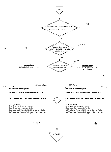
1 [0011] Figures 2A and 2B depict a flow chart of an auto-
optimization process
2 directed to optimizing the operation of an artificial lift system;
3 [0012] Figure 3 is a representation of a control panel for
monitoring and
4 controlling parameters of the auto-optimization process of Figures 2A and
2B; and
[0013] Figure 4 is a representation of an example dynamometer card and a
6 user-selected fluid pounding reference point for operation of the auto-
optimization
7 process.
8
9 SUMMARY
[0014] Generally, embodiments of a system and method for optimizing
11 performance of an artificial lift system are provided herein. The
optimization process
12 can be performed automatically by a controller of the artificial lift
system configured
13 to receive optimization parameters from the user and information regarding
the
14 performance of the lift system as inputs. The controller can then output
necessary
changes to the operation of the system, if any, to maintain operation within
the
16 optimization parameters. The user-selected optimization parameters can
include but
17 are not limited to, speed rate increase and decrease increments,
stabilization period
18 i.e. the number of strokes N required to be completed between each speed
rate
19 increase or decrease, minimum/maximum pump speed rates, target reference
points, and warnings/alarm notifications.
21 [0015] The optimization process can adjust the pumping speed of
the artificial
22 lift system in response to measured rod load and a position of the
downhole pump,
23 or the position of a hydraulic cylinder at surface configured to drive
and reciprocate
6
Date Recue/Date Received 2020-04-23
1 the pump. More particularly, the optimization process can increase or
decrease the
2 pump speed of the system in response to the measured rod load at a
reference
3 position relative to a target reference point comprising the reference
rod load at the
4 reference position. The target reference point can be selected to
indicate pump
inefficiencies. For example, the target reference point can indicate fluid
pounding if
6 the measured rod load at the reference position is greater than the
reference rod
7 load at the reference position. In other embodiments, the presence of
pump
8 inefficiencies can be assumed if the measured rod load is less than the
reference
9 road load. In embodiments, multiple target reference points may be used.
[0016] In embodiments, the optimization process can also be configured to
11 only adjust the pump speed after the user-selected stabilization period
has elapsed.
12 The process can also be configured to maintain pump speed above the
13 minimum/maximum pump speed rates.
14 [0017] In a broad aspect, a method of optimizing performance of
an artificial
lift system for producing fluid from a wellbore comprises: reciprocating a
downhole
16 pump between a lower position and an upper position with a pumping unit;
17 measuring a position of the pumping unit and an axial load of a rod
string of the lift
18 system; comparing the measured axial load of the rod string at a first
reference
19 position with a first threshold axial load at the first reference
position; and
automatically adjusting a pump speed of the pumping unit according to the
21 measured axial load at the first reference position relative to the
first threshold axial
22 load at the first reference position.
7
Date Recue/Date Received 2020-04-23
1 [0018] In an embodiment, adjusting the speed of the downhole
pump
2 comprises: if the measured axial load of the rod string at the first
reference position
3 is equal to or greater than the first threshold axial load, decreasing
the pump speed;
4 and if the measured axial load of the rod string at the first reference
position is less
than the threshold axial load, increasing the pump speed.
6 [0019] In an embodiment, the pumping unit is configured to
decelerate from
7 an upper deceleration point to an upper operational limit, and decelerate
from a
8 lower deceleration point to a lower operational limit, and the first
reference position
9 is between the upper and lower deceleration points.
[0020] In an embodiment, the method further comprises maintaining the
11 pump speed if increasing the pump speed would result in the pumping unit
12 exceeding the upper operational limit, and maintaining the pump speed if
13 decreasing the pump speed would result in the pumping unit exceeding the
lower
14 operational limit.
[0021] In an embodiment, the method further comprises determining a first
16 drift being the difference between the upper position and the upper
operational limit,
17 and a second drift being the lower position and the lower operational
limit, and
18 automatically controlling the operation of the pumping unit to minimize
the first and
19 second drifts.
[0022] In an embodiment, the method further comprises comparing the
21 measured axial load of the rod string at at least a second reference
position with at
22 least a second threshold axial load at the at least second reference
position, and
23 automatically adjusting the pump speed according to the measured axial
load at the
8
Date Recue/Date Received 2020-04-23
1 at least second reference position relative to the at least second
threshold axial load
2 at the at least second reference position.
3 [0023] In an embodiment, the step of decreasing the pump speed
further
4 comprises decreasing the pump speed by a speed decrease interval.
[0024] In an embodiment, the decrease interval is between the range of 1%
6 to 15% of the pump speed.
7 [0025] In an embodiment, the step of increasing the pump speed
further
8 comprises increasing the pump speed by a speed increase interval.
9 [0026] In an embodiment, the increase interval is between the
range of 1% to
15% of the pump speed.
11 [0027] In an embodiment, the method further comprises
maintaining the
12 pump speed above a minimum pump speed and below a maximum pump speed.
13 [0028] In an embodiment, the method further comprises
reciprocating the
14 pumping unit at least for a transition period comprising a minimum
number of stroke
cycles before adjusting the pump speed.
16 [0029] In another broad aspect, an artificial lift system
producing fluid from a
17 wellbore to surface comprises: a linear actuator comprising a movable
component
18 moveable between a lower position and an upper position and driveably
coupled to
19 a downhole pump via a rod string; a power unit coupled to said linear
actuator for
driving said movable component to reciprocate; the reciprocating of the
movable
21 component driving the downhole rod pump to pump fluid to the surface; a
position
22 sensor for detecting a position of the movable component; an axial load
sensor for
23 detecting an axial load on the rod string; and a controller coupled to
the position
9
Date Recue/Date Received 2020-04-23
1 sensor, the axial load sensor, and the power unit, the controller
configured to:
2 control the power unit for reciprocating said movable component between
the lower
3 .. position and the upper position at a pump speed; and automatically adjust
the pump
4 speed in response to the detected position and axial load.
[0030] In an embodiment, the controller is configured to automatically
adjust
6 the pump speed to avoid fluid pounding by decreasing the pump speed if the
7 measured axial load at a first reference position is equal to or greater
than a first
8 threshold axial load at the first reference position, and increasing the
pump speed if
9 .. the measured axial load at the first reference position is less than the
first threshold
axial load at the first reference position.
11 [0031] In an embodiment, the controller is further configured
to decelerate the
12 .. actuator from an upper deceleration point to an upper operational limit,
and
13 decelerate the actuator from a lower deceleration point to a lower
operational limit,
14 and the first reference position is between the upper and lower
deceleration points.
[0032] In an embodiment, the controller is further configured to maintain
the
16 pump speed if increasing the pump speed would result in the actuator
exceeding
17 the upper operational limit, and maintain the pump speed if decreasing the
pump
18 .. speed would result in the actuator exceeding the lower operational
limit.
19 [0033] In an embodiment, the controller is further configured
to compare the
axial load at at least a second reference position with at least a second
threshold
21 axial load at the at least second reference position, and automatically
adjust the
22 pump speed according to the measured force at the at least second reference
Date Recue/Date Received 2020-04-23
1 position relative to the at least second threshold axial load at the at
least second
2 reference position.
3 [0034] In an embodiment, the controller is configured to adjust
the pump
4 speed by increasing the pump speed by a speed increase increment or
decreasing
the pump speed by a speed decrease increment.
6 [0035] In an embodiment, the controller is configured to
maintain the pump
7 speed above a minimum pump speed and below a maximum pump speed.
8 [0036] In an embodiment, the controller is configured to
reciprocate the
9 movable component for a transition period comprising a minimum number of
stroke
cycles before adjusting the pump speed.
11
12 DETAILED DESCRIPTION OF THE EMBODIMENTS
13 [0037] According to embodiments herein, improved apparatus and
14 methodologies for controlling the operation of an artificial lift system
are provided.
The present apparatus and methodologies can dynamically respond to fluctuating
16 reservoir conditions in real-time, automatically analyzing each stroke of a
17 reciprocating downhole pump and maximizing pump fill to mitigate or
eliminate
18 pump-off conditions and fluid pounding. In some embodiments, the present
19 apparatus and methodologies for controlling the operation of the
artificial lift system
may adjust the pumping speed rate based upon the actual inflow rate or filling
of the
21 pump, maximizing filling of the pump in real-time during operation. The
present
22 apparatus and methodologies will now be described having regard to Figs.
1 to 4.
11
Date Recue/Date Received 2020-04-23
1 [0038] Having regard to Fig. 1, and by way of background, the
presently
2 improved apparatus and methodologies may provide improved monitoring and
3 control of known artificial lift systems, such as those systems described
in U.S.
4 Patent No. 8,851,860, entitled "Adaptive Control of an Oil or Gas Well
Surface-
Mounted Hydraulic Pumping System and Method", and in U.S. Patent No.
6 9,745,975, entitled "Method for Controlling an Artificial Lifting System
and An
7 Artificial Lifting System for Employing Same", both assigned to the owner of
the
8 subject invention.
9 [0039] The terms "speed rate", "pump speed", or "pump speed
rate" are
defined herein as a reciprocation rate or reciprocation speed of the downhole
pump
11 or surface pumping unit of the artificial lift system, for example in
units of strokes per
12 minute (SPM), and such terms are used interchangeably herein.
13 [0040] Referring still to Fig. 1 artificial lift systems 10
generally comprise a
14 cylindrical downhole pump 12 submerged within a wellbore 8 at a
predetermined
depth so as to be submerged in wellbore fluids. Fluid and gas F can flow from
the
16 reservoir into the wellbore through perforations in the wellbore casing
and into the
17 downhole pump 12. When the pump plunger 14 is reciprocated up and down
within
18 the pump barrel 16, pump 12 lifts the wellbore fluids from the reservoir to
the
19 surface. Pumped wellbore fluids F are directed into flow lines at the
ground surface
for downstream processing (e.g. into separation tanks, not shown). The
21 characteristics of the wellbore fluids F being produced may depend upon
the
22 particular reservoir, and may comprise at least oil, water, gas, or a
combination
12
Date Recue/Date Received 2020-04-23
1 thereof. Herein, the term "wellbore fluids" may be used interchangeably
with terms
2 such as "reservoir fluids", "production fluids", and/or "drilling
fluids".
3 [0041] Having further regard to Fig. 1, rod string 20 transmits
the
4 reciprocating motion from the surface mounted pumping unit 22 to the
downhole
pump 12. According to embodiments, the rod string 20 may comprise an assembly
6 of threaded steel or fiberglass rods, referred to as sucker rods, wherein
the
7 uppermost portion of the rod string 20 is a polished steel rod 20a that
is attached at
8 its upper end to the surface mounted pumping unit 22 through a carrier
bar adapter
9 or bridle 24. The lower part of the rod string 20b is attached to the
downhole pump
plunger 14. A stuffing box 26 seals against the reciprocating polished rod
20a,
11 enabling it to reciprocate in the fluid-filled wellbore 8 without
leaking fluid out of the
12 wellhead.
13 [0042] According to some embodiments, during pumping operation,
rod string
14 20 and pump 12 are reciprocated by means of the surface pumping unit 22
comprising a linear actuator such as a reciprocating hydraulic cylinder 30. In
16 embodiments, the cylinder 30 can be a dual-acting triple chamber type
cylinder,
17 wherein a movable component such as a piston 32 is reciprocated up and down
18 between an upper position and a lower position by the application of
hydraulic flow
19 and pressure alternatively to each side of the piston 32 via hydraulic
ports formed in
the cylinder 30. As would be understood, one advantage of the present system
is
21 the ability to fully monitor and control the position of the piston 32
at any point and
22 time, enabling concurrent control of its speed and acceleration. Control of
these
23 parameters is fundamental to optimization of the pumping speed and to the
13
Date Recue/Date Received 2020-04-23
1 productivity of the well, as will be described in further detail below.
Production can
2 thus be maximized by adapting the speed of the pumping unit 22 to
reciprocate at
3 the fastest reciprocation/pumping rate possible without pumping off the well
and
4 without experiencing pounding on its downstroke.
[0043] More specifically, with reference to Fig. 1, pumping unit 22 may
6 comprise at least two hydraulic chambers: one chamber being an 'UP'
chamber 34
7 and another being a 'DOWN' chamber 36. When a hydraulic pump 38, for
example
8 a fixed displacement hydraulic pump coupled to and driven by an electric
motor 40,
9 operates in a first direction, it directs the flow of hydraulic fluid
through first hydraulic
fluid line L1 to the UP chamber 34, raising the piston 32 within the cylinder
30.
11 When the hydraulic pump 38 is operated in a second direction, it directs
the flow of
12 hydraulic fluid through a second hydraulic fluid line L2 to the DOWN
chamber 36,
13 thereby lowering the piston 32 within the cylinder 30. Hydraulic flow
can be gated to
14 the UP chamber 34 and the DOWN chamber 36 by means of manually or
electrically operated shut off valves V1 and V2, respectively. Hydraulic
pressure can
16 be monitored in the UP and DOWN chambers 34,36 by pressure sensors Si and
17 S2, respectively. Accordingly, in some embodiments, reciprocal motion of
piston 32
18 is powered and controlled by the flow rate and direction of hydraulic
fluid the from
19 the hydraulic pump 38 to the cylinder 30, with the direction of piston 32
being
determined by the direction of operation of the hydraulic pump 38. If there is
no
21 flow into either of UP chamber 34 or DOWN chamber 36, the piston 32
remains in
22 place and the downhole pump 12 is idle.
14
Date Recue/Date Received 2020-04-23
1 [0044] A gas vessel 42 containing a suitable type of
pressurized gas, such as
2 nitrogen, can be coupled to a gas chamber 43 of the cylinder 30 for
providing
3 counterbalance to the weight of downhole components, such as the rod
string 20,
4 during operation of the artificial lift system 10.
[0045] A pulley 44 can be mounted on the top of the piston 32. A cable 46
6 can be wrapped around pulley 44, such that a first end of the cable 46 is
fixed to a
7 stationary location such as the base of the cylinder 30, and a second end
of the
8 cable 46 is attached to the polished rod 20a via the carrier bar adapter
24. As the
9 piston 32 and pulley 44 move up and down, the cable 46 rolls on the pulley
44.
Because one end of the cable 46 is fixed, its second end attached to the
carrier bar
11 18 moves up and down in parallel with the reciprocating piston 32. In
turn,
12 componentry attached to the second end of the cable 46, namely the rod
string 20
13 and the pump plunger 14, reciprocate with the stroke of the piston 32.
14 [0046] Various sensors, such as an axial load sensor and
position sensors,
can be positioned at appropriate locations of the system to monitor axial
forces on
16 the rod string 20 and the position of the piston 32 and/or pump plunger
14.
17 [0047] According to some embodiments, the present artificial
lift system 10
18 may comprise a power unit 50, such as an electrical generator, configured
to
19 provide power to the motor 40 and other components of the system 10. In
embodiments, a variable frequency drive (VFD) can be located between the power
21 unit 50 and motor 40 for controlling the speed thereof, in turn
controlling the speed
22 of pump 38. A controller 52, for example a programmable logic controller
(PLC), can
23 be coupled to the power unit 50 for controlling the operation of the system
10.
Date Recue/Date Received 2020-04-23
1 Further, the controller 52 can be connected to the various sensors of the
system 10
2 to monitor the performance thereof. The controller 52 can further comprise a
3 microprocessor, a memory, input/output interface and necessary circuitry
for
4 receiving inputs from the operator, executing machine-readable
instructions stored
in the memory, and providing instructions to the power unit 50. A control
panel 54
6 can be configured to display information regarding the operation of the
artificial lift
7 system 10 and enable an operator to manually control the operating
parameters
8 thereof. The control panel 54 may comprise a touch-sensitive screen and a
graphic
9 user interface (GUI) thereon for operators to input required system
parameters.
[0048] The motor 40 may comprise an electric motor operative to transfer
its
11 output torque directly to the input shaft of pump 38. The speed of the
motor 40 and
12 its direction of rotation can then be controlled by the controller 52
via the VFD by
13 adjusting the voltage and the frequency of AC power supplied to the
electric motor
14 40.
[0049] Pump 38 may be a fixed-displacement type pump, displacing a fixed
16 volume of flow per turn to the cylinder 30, such that the flow rate is
determined and
17 varied by the speed of rotation of the hydraulic pump 38. In
embodiments, the pump
18 38 may be another type of suitable pump capable of varying the flow rate to
the
19 cylinder in a controlled manner.
[0050] In operation, the controller 52 instructs the VFD to provide speed
input
21 parameters to the motor 40, such speed input parameters determining the
operation
22 of the cylinder 30 and the downhole pump 12. As will be described in
more detail,
23 instructions provided by the controller 52 are determined according to a
set of
16
Date Recue/Date Received 2020-04-23
1 control laws using optimization parameters provided by the operator and
2 measurements collected by the various sensors of the artificial lift
system 10 to
3 achieve the desired behavior of the system 10.
4 [0051] The present apparatus and methodologies provide a
significant
improvement over the known methods of monitoring and controlling artificial
lift
6 systems. For example, U.S. Patent No. 8,851,860 (the '860 Patent) teaches
a
7 method for monitoring and controlling motion of the cylinder 30 under
changing well
8 conditions. The '860 method requires the use of a predicted model to
optimize
9 productivity of the well, such predicted model being based on specific
well
conditions. The method creates the predicted model using the desired
production
11 rate, the given well depth, the well inflow pressure, the well fluid
type and
12 composition, and the pumping equipment characteristics such that an
"ideal model
13 of motion" is created and used as the desired optimal motion profile for
a specific
14 well that will produce maximum flow. The '860 Patent method is limited,
however,
as adjustment of the operation of the cylinder 30 only occurs when it is
determined
16 that the well conditions being monitored by the system differ from the
specific well
17 conditions of the predicted model. If the conditions of the well change
such that the
18 model is no longer applicable, a new model must be created in order to
maintain
19 optimized production, which may require cessation of pumping to acquire the
necessary data.
21
22
23
17
Date Recue/Date Received 2020-04-23
1 Auto-Optimization Process
2 [0052] By way of example, Fig. 2 provides a flow chart
depicting an
3 embodiment of the present improved process 100 for operating the
artificial lift
4 system 10. In embodiments, the process 100 for auto-optimizing operation
of the lift
system 10 begins at step 102 by the user selecting to enable the auto-
optimization
6 mode, for example at the control panel 54. In embodiments, as shown at
step 104,
7 the auto-optimization mode may only be engaged if/when a corresponding
Stroke
8 Control Mode is also engaged.
9 [0053] Stroke Control Mode ¨ As described in U.S. Patent No.
9,745,975, the
present artificial lift system 10 may also be monitored and controlled using
an
11 automatic "Stroke Control Mode" operative to ensure that the system
operates
12 within an allowable pump stroke range. For example, the controller 52 may
be
13 programmed to store a predefined top safety limit, representing a top
limit that the
14 piston rod 14 may safely extend thereto, and a predefined bottom safety
limit
representing a bottom limit that the piston rod 14 may be safely lowered
thereto.
16 Generally, for safety reasons, the top safety limit is lower than the
physical top limit
17 to which piston 32 can be extended, and the bottom safety limit is
higher than the
18 physical bottom limit to which piston 32 can be lowered. The top and
bottom safety
19 limits are typically determined during manufacturing of the system, and
are not user-
adjustable. During operation, however, the controller 52 may be programmed to
21 operate the piston 32 between a user-selected top operational limit
lower than the
22 top safety limit, and a user-selected bottom operational limit above the
bottom
23 safely limit, resulting in a user-defined stroke length. As would be
appreciated, the
18
Date Recue/Date Received 2020-04-23
1 actual top and bottom stop positions of the piston 32 may differ than the
user-
2 defined top and bottom operational limits, causing the actual stroke
length to vary
3 (normally within a relatively small range, such variation referred to as
"drift". The
4 Stroke Control Mode may be enabled in the present process 100 to
automatically
detect the actual top and bottom stop positions of the piston 32, and
automatically
6 adjust the operation of the system 10 to minimize the detected drift from
the user-
7 defined top and bottom operational limits and ensure that the position of
piston 32
8 remains within the selected range during operation. For example, when the
Stroke
9 Control Mode is enabled, the controller 52 can be configured to determine a
top
deceleration position, at which deceleration of the piston 32 commences during
the
11 movement thereof towards the top operational limit, and a bottom
deceleration
12 position, at which deceleration of the piston 32 commences during the
movement
13 thereof towards the bottom operational limit. The top and bottom
deceleration
14 positions can be calculated based on the detected drift to permit
deceleration at the
selected deceleration rate from the deceleration positions to the operational
limits.
16 Further, the controller 52 can adjust the top and bottom deceleration
positions to
17 eliminate drift between the actual top and bottom stop positions and the
top and
18 bottom operational limits, respectively, thereby fully utilizing the
allowable stroke
19 length and mitigating overshoot past the operational limits. More
specifically, if the
controller 52 detects that the actual top stop position is greater than the
top
21 operational limit, the controller 52 can adjust the top deceleration
position to be
22 lower, i.e. the piston 32 begins to decelerate earlier in the upstroke.
Conversely, if it
23 is detected that the actual top stop position is less than the top
operational limit, the
19
Date Recue/Date Received 2020-04-23
1 controller 52 can adjust the top deceleration position to be greater i.e.
the piston 32
2 begins to decelerate later in the upstroke. The same logic can be applied
to drift
3 between the actual bottom stop position and the bottom operational limit.
4 [0054] In embodiments, the present process 100 may not be
permitted to
proceed without first ensuring that the Stroke Control Mode is enabled. Such
6 automatic control of the stroke length and adjustment for drift provided
by the Stroke
7 Control Mode may be desirable as it mitigates the potential for the piston
32 to
8 overshoot the top and bottom operational limits and reach its physical top
and
9 bottom limits, potentially damaging the cylinder 30 or piston 32, due to
the changes
to reciprocation speed applied by the auto-optimization process 100. For
example, if
11 the Stroke Control Mode is disabled, the system's pump-off control (POC)
can
12 automatically turn on and the present auto-optimization process 100 cannot
be
13 enabled. In embodiments, an error message can also be displayed, for
example on
14 the control panel 54, to notify the operator that the auto-optimization
process 100 is
not able to proceed without the Stroke Control Mode also being enabled.
16 Conversely, if the Stroke Control Mode is enabled, the system's pump-off
control
17 (POC) can automatically be turned off and the present auto-optimization
process
18 100 can be enabled. A review of the set speed and cycle can then be
performed by
19 the operator, for example using the control panel 54, to confirm whether
the present
artificial lift system 10 is operating at maximum stroke length capacity
within the
21 user-defined stroke range, i.e. within the user-defined top and bottom
operational
22 limits per the Stroke Control Mode.
Date Recue/Date Received 2020-04-23
1 [0055] Returning to Fig. 2A, at step 106, the operator can
enter the various
2 optimization parameters of the auto-optimization process 100. At step 108,
the
3 process 100 validates the user-defined optimization parameters. The
optimization
4 parameters can include, but are not limited to, speed rate increase and
decrease
increments, stabilization period i.e. the number of strokes N required to be
6 completed between each speed rate increase or decrease, minimum/maximum
7 pump speed rate, target reference points, and warnings/alarms, described
in further
8 detail below. By way of example, Fig. 3 shows a picture of GUI screen
displayed on
9 control panel 54 that the user of the present system 10 may use to view
and select
parameters for the present auto-optimization process 100. In the present
11 embodiment, the upstroke and downstroke speed rates of the piston 32 are
also
12 shown on the GUI to illustrate to the user how changes to the optimization
13 parameters above affect said speeds of the piston 32. In the present auto-
14 optimization process 100, the upstroke and downstroke speed rates are not
manually adjusted by the user, but are instead variables dependent on the auto-
16 optimization process and the user-defined auto-optimization parameters.
Said
17 speed rates are displayed on the control panel 54 such that the user can
determine
18 whether they are increasing or decreasing as the present auto-
optimization process
19 100 runs. In the present example, the upstroke and downstroke speeds are
both
initially displayed as 33 strokes per minute (SPM), although it should be
appreciated
21 that the upstroke and downstroke speeds of the piston 32 need not be the
same.
22 [0056] Returning to the validation of user-defined parameters
at step 108 of
23 Fig. 2A, the user-defined auto-optimization parameters of speed rate
increase and
21
Date Recue/Date Received 2020-04-23
1 .. decrease increments, stabilization period i.e. the number of strokes N
required to be
2 completed between each speed rate increase or decrease, minimum/maximum
3 pump speed rates, and target reference points are described below.
4 [0057] Speed rate increase/decrease increments - The speed rate
increase
and decrease increments are the increments in which the auto-optimization
process
6 increases or decreases the stroke rate of the piston 32 in response to
measured
7 performance parameters of the system 10. In embodiments, such speed change
8 increments can be displayed as percentages of the present reciprocation
speed rate
9 of the piston 32. In some embodiments, the speed increase increment may
be set to
any number between an allowable range, for example between 1% and 15%,
11 wherein a default speed increase increment of 10% may be pre-selected.
In some
12 embodiments, the speed decrease rate may be set to any number between an
13 allowable range, for example between 1% and 15%, wherein a default speed
14 decrease increment of 10% may be pre-selected. In the present example,
as shown
.. in Fig. 3, the speed increase and decrease increments are displayed on the
GUI as
16 10%, although it should be appreciated that the increase and decrease
increments
17 .. need not be the same.
18 [0058] Stabilization period - The stabilization period
comprises the required
19 .. number of pump stroke cycles to be completed after an adjustment has
been made
to the pump speed rate by the auto-optimization process 1000 before a further
21 change in the speed rate can be affected. In embodiments, the
stabilization period
22 can be required to be greater than a minimum number of strokes, as
described in
22
Date Recue/Date Received 2020-04-23
1 further detail below. In embodiments, the stabilization period can be
required to fall
2 between a minimum and maximum number of strokes.
3 [0059] The use of a stabilization period is desirable as the
piston 32 may
4 initially overshoot a target top and bottom position immediately after
the pump
speed rate is increased, but then stabilize over time to consistently
reciprocate
6 between the target top and bottom positions. Such initial overshoot may
result in the
7 piston 32 travelling beyond the user-selected top or bottom operational
limits but
8 then stabilizing to a target top and bottom position within the
operational limits once
9 the Stroke Control Mode has optimized the stroke length. Further stroke
speed
increases implemented before the stroke length of the piston 32 has stabilized
can
11 result in overcompensation by the system 10 such that the actual top and
bottom
12 positions of the piston 32 consistently exceed the top or bottom
operational limits.
13 Therefore, it is desirable to require a stabilization period to have
elapsed to prevent
14 the controller 52 from applying any further changes to the pump speed
rate until the
stroke length has stabilized after a change in pump speed. In the present
16 embodiment, to account for the initial overshoot following a change in
stroke speed,
17 the controller 52 can require a stabilization period, for example a
minimum of four
18 (4) strokes, to permit the stroke length to stabilize before further
changes are made
19 to the stroke speed. In some embodiments, the stabilization period
following a
speed rate increase can be any number of strokes within an allowable range,
for
21 example between four (4) strokes to one thousand (1000) strokes, wherein
a default
22 stabilization period of five (5) strokes or another suitable period may
be selected. It
23 is preferable to require a higher number of strokes following a speed
increase to
23
Date Recue/Date Received 2020-04-23
1 provide sufficient time for the movement of the piston 32 to stabilize,
while keeping
2 the stabilization period short enough to permit the system 10 adapt
sufficiently
3 quickly to changes in wellbore pumping conditions. In the present
example, as
4 shown in Fig. 3, the prerequisite number of strokes that must be completed
following a speed increase is displayed on the GUI as four (4) strokes, in
other
6 words, the system will require the piston 32 to complete four stroke cycles
before
7 increasing the pump rate by the selected speed increase rate of 10%.
8 [0060] Conversely, when a speed rate decrease is executed by
the controller
9 52, the piston 32 may not utilize the full allowable stroke length
immediately after
the pump speed rate is decreased. Such initial undershoot may result in the
piston
11 .. 32 not travelling to the set top or bottom operational limits but then
stabilizing to the
12 target top and bottom positions once the Stroke Control Mode has optimized
the
13 stroke length. Further stroke speed decreases implemented before the
stroke length
14 of the piston 32 has stabilized can result in overcompensation by the
system 10
such that the full allowable stroke length of the piston 32 is consistently
not utilized.
16 Therefore, it is desirable to prevent the controller 52 from applying
any further
17 speed changes until the stroke length is stabilized such that the piston
32 utilizes all
18 of the allowable stroke length. To account for such an undershoot following
a
19 decrease in speed rate, in an embodiment, the controller 52 can require a
stabilization period, for example a minimum of four (4) strokes, to permit the
stroke
21 length to stabilize before further changes are made to the stroke speed.
In some
22 embodiments, the stabilization period following a speed rate decrease can
be any
23 number of stroke within an allowable range, for example between four (4)
strokes
24
Date Recue/Date Received 2020-04-23
1 up to one thousand (1000) strokes, wherein a default stabilization period
of ten (10)
2 strokes or another suitable period may be selected. In the present example,
as
3 shown in Fig. 3, the prerequisite number of strokes that must be completed
4 following a speed decrease is also displayed on the GUI as four (4) strokes.
It
should be appreciated that the prerequisite number of strokes for the speed
6 increase and speed decrease to complete need not be the same, that is,
separate
7 stabilization periods can be used for speed increases and speed
decreases.
8 [0061] In embodiments, the stabilization period can also be
selected to permit
9 the hydraulic fluid reservoir of the surface pumping unit 22 to stabilize
after an
adjustment to the pump speed rate, in addition to permitting the stroke length
to
11 stabilize.
12 [0062] Minimum/maximum pump speed rates - For safety reasons,
and to
13 prevent the potential freezing of components of the lift system 10, the
operator may
14 set minimum and maximum strokes per minute (SPM) for the pump speed rate,
such values being within the design specifications of the system 10 and/or
surface
16 pumping unit 22. In the present example, referring still to Fig. 3, the
controller 52
17 can be configured to maintain the pump rate speed between a minimum of 1
SPM
18 and a maximum of 5 SPM. As such, the present auto-optimization procedure
100
19 will automatically remain within the predetermined minimum and maximum SPM
limits, and will not make any speed rate changes that will cause the speed
rate
21 .. exceed those limits. For clarity, once the system 10has reached the
maximum SPM
22 limit of 5 SPM, the system will cease making increases to the SPM.
Similarly, once
23 the system has reached the minimum SPM limit of 2 SPM, the system will
cease
Date Recue/Date Received 2020-04-23
1 making motor speed changes to further decrease the SPM. In the present
example,
2 with reference to Fig. 3, the current SPM of the unit is displayed in
real-time on the
3 GUI as 2.8, such SPM thus falling within the minimum and maximum SPM
limits. In
4 embodiments, the minimum and maximum SPM limits can be set to any
desirable
range and can be updated as required.
6 [0063] Target reference points - as mentioned above, the
process 100 can
7 also receive target reference points from the user, such reference points
8 representing a desired reference axial rod load at a reference stroke
position of the
9 piston 32 or pump 12. At step 108, the controller 52 can review the
reference points
input by the user to verify they are within an acceptable range. If so, the
controller
11 52 will accept the input reference points. Otherwise, an error message
can be
12 displayed to the user, for example on control panel 54, requesting the
user to input
13 valid reference points. In an embodiment, an acceptable range for the
target
14 reference point can comprise a maximum load equal to or less than the
maximum
structure load, i.e. the maximum design load of the pumping unit 22, and a
minimum
16 load greater than the load at which the controller 52 engages a "slow
speed down"
17 process to slow the pump speed in the event of an unexpectedly low rod
load.
18 Further, an acceptable range for the piston position of the target
reference point can
19 be between the bottom deceleration position and top deceleration position
as
selected by the Stroke Control Mode.
21 [0064] The target reference points comprise one or more set
points
22 representing a reference rod load value at a reference stroke position
that is desired
23 to be maintained by the system. For example, a dynamometer card can be
26
Date Recue/Date Received 2020-04-23
1 produced for a given wellbore as the rod string 20 moves through each
stroke cycle,
2 whereby the card plots the load measured on the rod string 20 in relation to
the
3 position of the piston 32 or pump 12. As shown by the hatched line in
Fig. 4, an
4 ideal dynamometer card charts a rectangular or parallelogram shape,
indicative of
the fluid load being rapidly picked up and lifted by the pump 12 for the
duration of
6 the up-stroke, and then being rapidly released as the pump 12 begins the
7 downstroke. Deviation from the shape of this ideal dynamometer card can
indicate
8 inefficiencies in the pumping cycle, such as pump-off and/or fluid
pounding.
9 [0065] According to embodiments herein, an operator may
determine target
reference points, i.e. rod load and piston/position values, that are desired
for the
11 system 10 to achieve or outperform in order to avoid pumping
inefficiencies such as
12 pump-off and fluid pounding. The target reference points can be entered
into the
13 system and the present auto-optimization process 100 will automatically
adjust the
14 pump speed rate in order to maintain operation of the lift system 10
within the
parameters specified by the target set points, thereby mitigating pumping
16 inefficiencies.
17 [0066] For example, with reference to Fig. 4, the solid line
illustrates a
18 dynamometer card indicative of the presence of fluid pounding in the
system 10.
19 One or more fluid pounding target reference points X1,Y1 can be selected
and input
into the present system. The fluid pounding target reference points can be
selected
21 such that a measured rod load Y at or greater than the reference rod
load Y1 at
22 reference position X1 can be interpreted to indicate the presence of
fluid pounding.
23 In other words, if measured rod load Y at position X1 is above reference
rod load
27
Date Recue/Date Received 2020-04-23
1 Y1, then fluid pounding can be assumed to be present in the system 10.
The
2 present auto-optimization process 100 can be configured to automatically
adjust the
3 pump speed rate to maintain the measured rod load Y below reference rod
load Y1
4 at reference position X1 to avoid fluid pounding. The use of such
reference points in
the auto-optimization process 100 is advantageous as the reference points can
be
6 quickly updated by the operator if it is found that the previous
reference points are
7 no longer accurate in predicting pump inefficiencies, for example due to
a change in
8 wellbore conditions. Such updating of reference points can be performed
faster than
9 updating a wellbore model as required for conventional processes.
[0067] During operation, the present system 10 monitors and compares the
11 actual rod load with the fluid pound reference point by determining the
actual load Y
12 at the fluid pound reference position X1 during the downstroke. If, the
actual rod
13 load Y is less than the fluid pound reference load Y1 at the fluid pound
reference
14 position X1, the pump fillage is sufficient and the controller 52 can
either increase
the pumping speed rate of the system 10 or not make any changes to the speed
16 rate. If, however, the actual load Y is equal to or greater than the
fluid pound
17 reference load Y1 at the fluid pound reference location X1, the
controller 52 can
18 conclude that fluid pounding is occurring and automatically adjust to
correct the
19 inefficiency, as described in further detail below.
[0068] Returning to step 108 of Fig. 2, once the auto-optimization
parameters
21 have been reviewed and accepted by the user, and the target reference
points are
22 determined by the controller 52 to be valid, the present process 100 can
then check
23 as to whether processes incompatible with the auto-optimization process 100
are
28
Date Recue/Date Received 2020-04-23
1 running. For example, as shown in Fig. 2 at step 110, the controller 52
detects
2 whether any of three processes referred to herein as "high cylinder up
pressure",
3 "unit short stroking", and "PID" are enabled, such processed explained in
further
4 detail below. If the controller 52 determines that any of these processes
are running,
the controller 52 can be configured to inhibit further steps of the auto-
optimization
6 .. process 100 and can return to step 108 or another previous step. If the
controller 52
7 determines that none of these processes are running (i.e. systems are
OFF), the
8 auto-optimization mode 100 can proceed. Alternatively, the controller 52 can
be
9 configured to disable the enabled incompatible processes and proceed to
step 112
of the auto-optimization process 100.
11 [0069] High cylinder up pressure refers to methods for
detecting pump issues
12 by monitoring hydraulic pressures on the upstroke, for example increases in
peak
13 polished-rod load (PPRL). Where it is determined that the hydraulic
pressure
14 exceeds an adjustable set point, the artificial lift system 10 will
adjust by changing
its direction to the downstroke. The controller 52 can be configured to not
proceed
16 further with the auto-optimization process 100 until such a condition is
remedied.
17 Unit short stroking refers to methods for progressively increasing the
stroke length
18 of the unit upon initiation, for example to controllably 'short stroke'
the first few
19 strokes of the unit (e.g. a few inches) to allow the system to 'warm
up', and then to
gradually increase the stroke length to reach operation set points. The
controller 52
21 can be configured to not proceed further with the auto-optimization
process 100
22 until the short stroking is remedied. PID refers to proportional-
integral-derivative
23 controller, which is a control loop feedback mechanism that automatically
applies
29
Date Recue/Date Received 2020-04-23
1 correction to a control function. Moreover, the system's casing level
control feature,
2 relating to methods for addressing variable or unstable oil levels within
the wellbore
3 (i.e. whereby the system limits the unit speed to 1 SPM if the column
load is less
4 than an adjustable set point), may also be evaluated. The controller 52 can
be
configured to not proceed further with the auto-optimization process 100 until
the
6 well is no longer in an out-of-balance start up condition.
7 [0070] It is preferable to run the auto-optimization process
100 with the above
8 processes disabled, as said processes can cause speed rate changes that may
9 interfere with the speed changes made by the auto-optimization process
100, and
can create or take place in unstable conditions which are not conducive to the
11 .. comparison of measured rod load and position with the set reference
point to
12 determine the need for pump speed changes. For example, "high cylinder up
13 pressure" occurs when load increases due to a problem downhole, Unit Short
14 Stroking occurs during unit start up and after each manual speed change
when the
system has not stabilized, and PID occurs when there is a loss of load during
the
16 downstroke.
17 [0071] At step 112, the system's 10 pump-off control and casing
level control
18 features can be automatically disabled, and the controller 52 begins its
auto-
19 optimization evaluation during the next downstroke (B-2; step 114). With
reference
to Fig. 2B, in embodiments, during the downstroke, the auto-optimization
process
21 100 can determine and confirm that the SPM is within the minimum and
maximum
22 SPM (step 116). Moreover, the auto-optimization process 100 can confirm
that the
23 top and bottom deceleration points are established per the Stroke
Control Mode to
Date Recue/Date Received 2020-04-23
1 ensure that the stroke length remains within the selected top and bottom
operational
2 limits. If any of the above requirements are not met, the controller 52
can be
3 configured to not proceed any further with the auto-optimization process 10
and
4 resume its evaluation on the next downstroke, repeating steps 104 ¨ 114. The
controller 52 can further be configured to return an error message or
otherwise
6 notify the operator that there is an issue with the operation of the
system 10.
7 [0072] At step 117, the process 100 verifies whether the
stabilization period
8 has elapsed, i.e. the requisite number of stroke cycles have been
completed, since
9 the most recent stroke speed change. If not, then the process 100 can
repeat until
the required number of stroke cycles have been completed.
11 [0073] If the foregoing requirements are met, the present auto-
optimization
12 process 100 proceeds to step 118 to optimize the performance of the lift
system 10
13 by performing a comparison of the measured rod load Y with the target
reference
14 rod load Y1 and, based upon the comparison, adjust the upstroke and/or
downstroke speeds accordingly if necessary. Utilizing measured rod load values
Y
16 and the target reference rod load value Y1 indicative of pump
inefficiencies, the
17 present system can adapt, in real-time, to variations in wellbore
conditions to
18 maintain optimized production and reduce operational inefficiencies.
19 [0074] For example, if it is determined that the actual rod
load value Y is less
than the reference rod load value Y1, the pump fillage is sufficient and the
system
21 can automatically apply the selected speed rate increase (e.g. 1% to
15%) to the
22 upstroke and/or downstroke to optimize the system's pumping rate (step
120). The
23 new speeds are loaded within the system, and the number of strokes
completed
31
Date Recue/Date Received 2020-04-23
1 since the most recent speed rate change N can be reset for the purposes
of
2 ensuring no further speed rate changes are made during the stabilization
period.
3 The new speed is applied in the next upstroke, and the controller 52 can
wait for the
4 number of stroke cycles required by the transition period to be completed
before
making another speed change. It should be appreciated that where both the
6 upstroke and downstroke speeds are to be increased, both up and down motor M
7 speeds will increase. By increasing the upstroke and/or downstroke speeds in
8 response to the confirmation that fluid pounding is not occurring as
indicated by
9 comparison with the fluid pounding reference point, performance of the
artificial lift
system 10 is maximized in real-time without dependence on developing updated
11 well models.
12 [0075] Alternatively, at step 122, if it is determined that the
actual rod load
13 value Y is greater than, or equal to, the reference rod load value Yl,
the system 10
14 is likely experiencing fluid pounding, and the system will automatically
apply the
selected speed rate decrease (e.g., 1% to 15%) in upstroke and/or downstroke
16 speeds. The new speeds are loaded within the system, and the number of
strokes
17 completed since the most recent speed rate change N can be reset for the
18 purposes of ensuring no further speed rate changes are made during the
19 stabilization period. The new speed is applied in the next upstroke, and
the
controller 52 waits for the number of strokes required by the transition
period to be
21 completed before making another sped change. It should be appreciated
that where
22 both the upstroke and downstroke speeds are to be decreased, both up and
down
23 motor M speeds will decrease. By decreasing the upstroke and/or downstroke
32
Date Recue/Date Received 2020-04-23
1 speeds in response to detected fluid pounding as indicated by comparison
with the
2 fluid pounding reference point, damage to the artificial lift system is
mitigated in real-
3 time without dependence on developing updated well models.
4 [0076] While only one fluid pounding reference point X1,Y1 is
set in the
above example, in embodiments, multiple fluid pounding reference points can be
6 .. set to provide greater control over the behaviour of the lift system 10
by the process
7 100.
8 [0077] In embodiments, other reference points besides fluid
pounding
9 reference points can be set to identify other inefficiencies in the
operation of the lift
system 10, and the process 100 can be adapted to adjust operation of the
system
11 10 in real-time to mitigate the effects of said inefficiencies while
maximizing
12 production.
13 [0078] The above auto-optimization process 100 can repeat
periodically to
14 continually adjust the pump speed of the system 10. For example, the
process 100
can repeat every 10 minutes beginning at step 112 until the auto-optimization
mode
16 is disengaged, or an operator changes the parameters of the auto-
optimization
17 process 100, at which point the process 100 can continue from step 108.
18 [0079] Under all operating conditions, a local or remote
operator has the
19 ability to override the presently described lift system 10 and auto-
optimization
process 100, returning full control of the system to the operator.
Intervention of the
21 operator is enabled by direct or remote interface with the controller
52.
33
Date Recue/Date Received 2020-04-23
1 [0080] While certain embodiments of the auto-optimization process 100
and
2 system 10 are described herein, alternative processes may be implemented
without
3 deviating from the scope of the present invention.
4 [0081] Although embodiments have been described above with reference
to
the accompanying drawings, those of skill in the art will appreciate that
variations
6 and modifications may be made without departing from the scope thereof as
defined
7 by the claims.
8
9
34
Date Recue/Date Received 2020-04-23