Note : Les descriptions sont présentées dans la langue officielle dans laquelle elles ont été soumises.
CA 03079372 2020-04-16
WO 2019/077338 PCT/GB2018/052981
1
HAIR STYLING DEVICE, HAIR STYLING METHOD AND DRIVE SYSTEM
FIELD OF THE INVENTION
This invention relates to a hair styling device, to a hair styling method, and
to a drive system
suitable for use in the hair styling device. The invention relates in
particular to a hair waving
device.
BACKGROUND TO THE INVENTION
A hair styling device is described in W095/22920, by one of the present
inventors.
W095/22920 discloses a method of styling a section (or length) of hair by
inserting the section
of hair into a resilient tube of latex or the like, the tube being stretched
lengthwise and the ends
of the tube being secured to respective parts of the section of hair. The
resilient tube is allowed
to contract whereupon the contained section of hair is forced into a wavy
form. The hair can be
treated before or after insertion into the tube so that the wavy form is
maintained after the hair
has been removed from the tube.
W095/22920 also describes a device for use in the method. Improved devices for
use in similar
hair styling methods are described in the later applications W097/46132,
W000/57744,
W000/08967 and W02012/153118.
The published application W02014/122442 describes a further improved hair
styling device in
which a section of hair is drawn into a styling chamber by the relative
movement of driving
members and forming members in the chamber. One or more driving members press
the
section of hair into a hair-receiving region between neighbouring forming
members to create the
desired wave. Heat and/or treatment products can be applied to the section of
hair to set the
wave. It is a particular advantage of W02014/122442 that the driving members
can be moved
sequentially so that the tension applied to the section of hair is minimised.
All of the above-described documents drive a section of hair into a wavy form
and can be
described as hair waving devices. The present invention similarly drives a
section of hair into a
wavy form, and can be considered to be a further improvement upon these known
hair waving
devices.
Another type of hair styling device is described in each of W02009/077747,
W02012/080751,
W02013/186547 and W02015/132594. These documents describe devices in which a
section
of hair is wound around an elongate member so that the section of hair is
formed into curls
rather than waves.
Hair crimpers also force a section of hair into a wavy form, the crimpers
comprising a pair of
plates each having a series of corrugations of substantially triangular form.
The plates are
designed to fit together with the peaks of the corrugations of one plate
fitting into the troughs of
the corrugations of the other plate, and vice versa. The plates are usually
heated so as to style
the hair into the desired crimped form. The waves which are created by hair
crimpers are
typically much smaller in amplitude and wavelength than those created by the
methods and
apparatus of the patent documents listed above.
CA 03079372 2020-04-16
WO 2019/077338 PCT/GB2018/052981
2
A "hair waver" is a product which is similar to hair crimpers in that the hair
is clamped between
two complementary heated surfaces. In hair wavers the complementary surfaces
are usually
curved with a relatively large radius of curvature so that the waves in the
user's hair are
considerably larger than those formed by crimpers. Particular products of this
type are referred
to as a "jumbo waver" or "deep waver" to emphasise the relatively large size
of the waves which
are produced in the section of hair.
GB303043 describes a hair waver comprising a pair of corrugated plates which
are pivoted
together, the peaks of the corrugations of one plate fitting into the troughs
of the corrugations of
the other plate whereby to clamp the hair between the plates and form the hair
into waves in a
first direction. Alternate corrugations of one plate are moveable
longitudinally in a second
direction relative to their neighbouring corrugations, and also relative to
the corrugations of the
other plate, the second direction being perpendicular to the first direction
whereby to seek to
form a more complex wave.
SUMMARY OF THE INVENTION
The inventors have conceived an alternative apparatus and method for creating
waves in a
section of hair, and the present invention is directed to this apparatus, and
to the method of use.
The apparatus and method have advantages over the known apparatus and methods
as set out
below. The present invention is also directed to a drive system suitable for
use in a hair styling
device.
According to a first aspect of the present invention there is provided a hair
styling device for
imparting a wave to a section of hair without clamping the section of hair in
the wave form, the
device having a first forming member and a second forming member, a hair-
receiving region
between the first forming member and the second forming member, and a driving
member
which is movable in a first direction relative to the first forming member and
the second forming
member into the hair-receiving region and which is adapted to drive the
section of hair into the
hair-receiving region, the driving member being movable relative to the first
forming member
and the second forming member also in a second direction, the second direction
being at an
angle to the first direction whereby to further move the section of hair in
the hair-receiving
region.
In common with W02014/122442 the hair is not clamped between heated plates in
the present
invention. The inventors have found that avoiding any clamping of the hair
allows the hair to
form waves with a more natural curve which can produce a more aesthetically
pleasing wave.
Also, the likelihood of damage to hair is known to increase if the hair is
heated to a styling
temperature and clamped at the same time, so the avoidance of any clamping
significantly
reduces the likelihood of damage.
W02014/122442 discloses arrangements in which the driving members move into
the hair-
receiving regions in a single stage of movement, and specifically in the first
direction; the driving
members do not also move in a second direction to further move the section of
hair in the hair-
receiving regions. In the arrangement of Figs. 23-27 in particular, the
driving member is a spiral
with a continuous (rotational) movement, the increasing radius of the spiral
pressing the section
of hair (downwardly as viewed) into the hair-receiving regions in a single
direction of movement.
CA 03079372 2020-04-16
WO 2019/077338 PCT/GB2018/052981
3
The movement of the present driving member in two stages and in two different
directions, and
the consequential pressing of the section of hair into the hair-receiving
region in two different
directions, provides a three dimensional wave, such a wave being aesthetically
desirable to
many users. A three dimensional wave is envisaged in W02014/122442 and an
alternative
arrangement to Figs. 12-18 is disclosed in which the sides of the driving
members and forming
members are oppositely angled to promote a three-dimensional wave. That
embodiment relies
upon the section of hair moving laterally as it engages the angled sides, and
is not as reliable or
repeatable as the present invention which positively drives the section of
hair into a three-
dimensional form by virtue of the two stage movement of the driving member in
two different
directions.
Preferably, the movement of the driving member is linear in the first
direction and/or in the
second direction. The second direction can be substantially perpendicular to
the first direction
so that the driving member can initially press the section of hair directly
into the hair-receiving
region and can subsequently move the section of hair directly along the hair-
receiving region.
It will be understood that perpendicular movements of the driving member are
not necessary
and in practical embodiments there can be an acute angle between the first and
second
directions of movement of the driving member. It is nevertheless expected that
embodiments in
which there is an acute angle between movements in the first and second
directions will be
mechanically simpler than embodiments in which the first and second directions
are
perpendicular.
It is not intended that there is any pause in the movement of the driving
member between the
first and second stages, although that is not excluded. Also, it is expected
that in practical
devices there will not be a defined junction between the movements in the
first direction and the
second direction, and on the contrary it is expected that the driving member
will move along a
curved path joining the first stage movement in the first direction and the
second stage
movement in the second direction. In practical embodiments therefore it may
not always be
possible to determine precisely where the first stage of movement terminates
and the second
stage of movement commences, but it will nevertheless be possible to identify
two stages of
movement in two different directions.
Preferably, the hair-receiving region is in the form of an elongate channel or
slot and the first
and second forming members are elongated in the direction of the longitudinal
axis of the
channel (the forming members being in the form of rails or beams for example).
During the first
stage of movement the driving member can move into the channel and during the
second stage
of movement the driving member can move along the channel. The driving member
can also
be of elongate form, e.g. a rail or beam.
In W02014/122442 the hair-receiving regions have a relatively small dimension
in the direction
perpendicular to the first direction. The hair-receiving regions are not
required to be in the form
of channels (or otherwise elongate) since unlike the present invention they
are not required to
accommodate any significant movement of the section of hair in the second
direction.
In its simplest form the device comprises only two forming members and a
single driving
member and can impart a single wave into the section of hair. In a preferred
embodiment,
however, there are multiple forming members defining multiple hair-receiving
regions, and
CA 03079372 2020-04-16
WO 2019/077338 PCT/GB2018/052981
4
multiple driving members, so as to impart multiple waves into the section of
hair. Preferably, a
hair-receiving channel is provided between each pair of neighbouring forming
members.
In embodiments having multiple driving members, it is preferably arranged that
the driving
members move sequentially so as to minimise the tension applied to the section
of hair as it is
deformed by the driving members. The first driving member can stop moving in
the second
direction before the second driving member is moved in the first direction,
although some
overlapping movement of the driving members may be provided (and overlapping
movement is
preferred for those embodiments utilising the disclosed drive system).
The absence of
clamping of the section of hair enables the hair to move in the hair-receiving
regions with a
minimum of resistance as successive driving members cause the section of hair
to deform.
Preferably, one or more parts of the device are heated whereby to heat the
section of hair
during the waving process. Whilst the use of an external hair dryer is not
excluded, the direct
heating by way of electrical heating elements or the like mounted to the
device is preferred. For
example, some or all of the forming members (and also some or all of the
driving members, as
applicable) can contain electrical heating elements.
Desirably, a chamber is provided to contain the section of hair during the
waving process. In
such embodiments the forming and driving members are located in the chamber.
Also in such
embodiments one or more of the walls of the chamber may be heated by way of
respective
electrical heating elements.
One embodiment of the device has a body and a closure part or lid, the closure
part being
movable relative to the body between an open position in which a section of
hair can be
introduced into the device, and a closed position in which the chamber is
substantially closed. It
can be arranged that the proximal (or scalp) end of the section of hair is
clamped when the
closure part is in its closed position, this being possible since the proximal
end of the section of
hair does not usually need to move relative to the device during the styling
operation.
Nevertheless, it is preferred that the proximal end (as well as other parts of
the section of hair
which are not to be styled) will not be clamped by the device. Preferably, the
(movable) driving
member(s) are mounted to the body and the (fixed) forming members are mounted
to the
closure part. Preferably also, the control mechanism for the driving member(s)
is mounted in
the body.
Preferably, in embodiments having multiple driving members, a hair-receiving
region is also
provided between each pair of adjacent driving members, and the forming
members therefore
effectively act also to drive or press the section of hair into the hair-
receiving region(s) between
adjacent driving members. The term "driving member" is used herein to describe
the movable
hair-deforming component and the term "forming member" is used to describe the
non-movable
or fixed hair-deforming component (where movement is considered relative to
the body of the
device). This does not preclude the possibility that both of the driving
member(s) and forming
members are movable relative to a body of the device, although such
embodiments are likely to
be significantly more mechanically complex.
In common with W02014/122422, the provision of a chamber with a closure part
serves four
main purposes. Firstly, in embodiments in which the chamber is heated the
closure part can
reduce the loss of heat by way of convection through the hair-entry opening.
Secondly, in those
embodiments in which the chamber is heated, the closure part can reduce the
likelihood of the
CA 03079372 2020-04-16
WO 2019/077338 PCT/GB2018/052981
user touching a heated surface of the device. Thirdly, the closure part can
reduce the likelihood
of extraneous hair being engaged by the moving components in the chamber which
might
otherwise cause entanglement and/or discomfort to the user. Fourthly, if a
hair-treatment
product is used to help style a section of hair, a substantially closed
chamber can reduce the
5 amount of (vaporised) product which escapes into the environment.
Desirably, the forming members have a curved surface around which the section
of hair bends
as it is deformed during operation of the device. Desirably also, the driving
member(s) have a
curved surface which is engageable with the section of hair during use. The
provision of curved
surfaces assists the sliding of the hair past the forming members and driving
member(s) as the
wave is formed, and thereby minimises the tension in the section of hair as it
is being deformed
by the driving member(s).
In some embodiments there are between three and ten forming members and one
fewer driving
member. In a preferred embodiment there are five driving members and six
forming members,
each neighbouring pair of forming members providing a hair-receiving region
into which (and
along which) a respective driving member can move.
It will be understood that, during the first stage of movement, each driving
member moves from
its start or rest position in the first direction to an intermediate position,
and then, during the
second stage of movement, in the second direction to a limit or extreme
position. The distance
between the start position and the limit position largely determines the
length of the section of
hair in each of the waves produced by the device. Accordingly, the largest
deformation of the
section of hair occurs when the driving member is in its limit position. There
are of course
further stages of movement in each cycle of operation during which the driving
member moves
back to the start position, but the terms two-stage movement, first stage and
second stage refer
herein to movements of the driving member which increase the deformation in
the section of
hair, i.e. to movements of the driving member towards the limit position.
In some embodiments the length of the section of hair in each wave can be
varied by allowing
adjustment (by the user) of the limit position, for example adjustment of the
distance by which
the driving member moves in the second direction.
It will be understood that the natural resilience of hair will cause the
section of hair to tend to
relax after the driving member(s) have stopped moving upon reaching their
limit position, i.e. the
individual hairs in the section of hair will seek to straighten out and
thereby soften any sharp
corners through which the hairs have been bent. The degree to which the
section of hair will
relax is determined partly by the user's hair type, partly by the temperature
to which the section
of hair is heated, and partly by whether the user's hair is wet or dry
(amongst other factors).
The inventors have realised that it is desirable to permit the hair to relax
as that creates softer
curves in the section of hair and a more natural looking wave. Thus, whilst
the wave could be
set with the driving member(s) in the limit position, that is likely to create
a wave with sharp
curves and a less-aesthetically pleasing appearance. The inventors prefer not
to rely upon the
(unreliable and variable) tendency of the hair to relax, and instead assist
the relaxation of the
hair by optionally retracting the driving member(s) away from the limit
position before the wave
is set.
Alternatively stated, it will be understood that in addition to the above
factors, the ability of the
hair to relax into a more natural looking wave is in part limited by the
resistance to movement of
CA 03079372 2020-04-16
WO 2019/077338 PCT/GB2018/052981
6
the section of hair relative to the driving and forming members; by retracting
the driving
member(s) away from the limit position the engagement between the driving
member(s) and the
section of hair is reduced (or perhaps eliminated), and the tension in the
section of hair is
reduced, both of which increase the ability of the section of hair to relax
into a more natural
looking wave in the hair-receiving region.
According to a second aspect of the present invention there is provided a hair
styling device for
imparting a wave to a section of hair, the device having a first forming
member and a second
forming member, a hair-receiving region between the first forming member and
the second
forming member, and a primary driving element which is movable relative to the
first forming
member and the second forming member and which is adapted to move the section
of hair in
the hair-receiving region in a hair-deforming direction, the device having a
secondary driving
element which is movable relative to the first forming member and the second
forming member
and which is adapted to move the section of hair in the hair-receiving region
in a direction
opposed to the hair-deforming direction.
W02014/122442 discloses arrangements in which driving elements move into the
hair-receiving
regions in a hair-deforming direction; there are, however, no secondary
driving elements
adapted to drive the section of hair in a direction opposed to the hair-
deforming direction. In the
arrangements of Figs. 23-27 and Figs. 28-32 in particular, the driving
elements enter into and
then reverse out from the hair-receiving regions and that permits the section
of hair to relax in
the hair-receiving regions. The inventors have found, however, that it is
preferable to positively
drive the section of hair into a more relaxed position so as to make the
softening of the wave
more reliable and repeatable (and more uniform if multiple waves are formed
along a section of
hair).
As above described, the inventors have found that crimpers and hair wavers do
not create the
most natural looking and aesthetically pleasing waves because the hair is
clamped as it is being
styled. On the contrary, the appearance of the wave created by the present
invention is
enhanced by allowing the section of hair to relax into a space in which it can
adopt its most
natural curvature, ideally free of any tension or clamping. Accordingly,
whilst the section of hair
is initially driven by the secondary driving element to a more relaxed
position, it can be arranged
that the secondary driving element releases the hair in that more relaxed
position, so that the
final curvature of the section of hair is determined primarily by the hair
itself rather than by
surfaces of the device.
According to a third aspect of the invention there is provided a method of
styling a section of
hair with a device having a first forming member and a second forming member,
a hair-receiving
region between the first forming member and the second forming member, a
primary driving
element which is movable relative to the first forming member and the second
forming member,
and a secondary driving element which is movable relative to the first forming
member and the
second forming member, the method comprising the steps of:
fil moving the primary driving element relative to the first and second
forming members to
move the section of hair in the first hair-receiving region in a hair-
deforming direction,
{ii} moving the secondary driving element relative to the first forming member
and the second
forming member to drive the section of hair in the hair-receiving region in a
direction
opposed to the hair-deforming direction.
CA 03079372 2020-04-16
WO 2019/077338 PCT/GB2018/052981
7
The primary and secondary driving elements may move together relative to the
first and second
forming members. In step {i} the primary driving element may move in the hair-
deforming
direction to a limit position; in step {ii} the secondary driving element may
move in the reverse
direction to a retracted position, or alternatively back to the start
position.
It is preferably arranged that the wave is not set in the section of hair
until the secondary driving
element has undertaken the (reverse) movement and the wave has been driven
into the more
relaxed position. In embodiments in which the wave is set by the application
of heat it can be
arranged that the desired operating temperature is not reached until after the
secondary driving
element has completed the reverse movement. The preferred sequence of
operations is
therefore to drive the section of hair in the hair-receiving region in the
hair-deforming direction,
to drive the section of hair in the hair-receiving region in the reverse
direction into a more
relaxed position, and then to set the wave.
Ideally, the section of hair is released from the secondary driving element
(and also from the
primary driving element) before the wave is set.
In embodiments combining the first and second or the first and third aspects,
the primary and
secondary driving elements can be carried by a driving member. Also, the
secondary driving
element can be adapted to drive the section of hair in a reverse direction
opposed to the second
direction.
The secondary driving element can itself move in the reverse direction, or it
can move along a
more complex path with a component of movement in the direction opposed to the
hair-
deforming direction. Similarly, the section of hair can be driven by the
secondary driving
element along a path with a component of movement in the direction opposed to
the hair-
deforming direction. Accordingly, it is recognised that the invention
according to the second
and third aspects does not require the section of hair to be driven directly
in the direction
opposed to the hair-deforming direction; provided that the secondary driving
element has at
least a component of movement in the direction opposed to the hair-deforming
direction it will
permit the section of hair to move at least partly in that direction and
thereby relax into a more
natural looking wave.
Preferably the primary and secondary driving elements are connected to move
together, ideally
being parts of a unitary component. In embodiments in which the primary and
secondary
driving elements move together in the reverse direction opposed to the hair-
deforming direction,
movement of the primary driving element in the reverse direction releases the
section of hair
allowing it to relax, and movement of the secondary driving element in the
reverse direction
drives the section of hair to a more relaxed position.
In some embodiments the device has a defined (retracted) position to which the
secondary
driving element is reversed in the direction opposed to the hair-deforming
direction. Preferably,
however, the secondary driving element reverses fully, i.e. it moves all the
way back to the start
position, before the wave is set. In embodiments having multiple primary
driving elements and
multiple secondary driving elements, ideally all of the secondary driving
elements move together
to the retracted or start position, it being recognised that there is little
or no tension upon the
section of hair during this part of the driving elements' movement.
CA 03079372 2020-04-16
WO 2019/077338 PCT/GB2018/052981
8
According to a fourth aspect of the present invention there is provided a hair
styling device for
imparting a wave to a section of hair without clamping the section of hair in
the wave form, the
device having a first forming rail and a second forming rail, a hair-receiving
channel between the
first forming rail and the second forming rail, and a driving rail which is
movable in a first
direction between a position outside the hair-receiving channel and a position
in the hair-
receiving channel, the first driving rail also being movable in a second
direction along the hair-
receiving channel.
The terms "channel" and "rail" are used to clarify the elongate form of the
respective
components according to this aspect of the invention, but are otherwise not
limiting to the form
of those components.
Whilst the embodiments of W02014/122422 are shown and described imparting a
wave to a
section of hair comprising a small bundle, the invention according to this
aspect is suited
primarily to impart a wave into a ribbon-like section of hair. Whilst the
terms "bundle" and
"ribbon" are not precisely defined, they are distinguished herein in that a
bundle has a similar
width and depth whereas a ribbon has a much greater width than depth. In
particular, the
provision of an elongate channel and elongate forming rails and driving
rail(s) allows the user to
style a greater volume of hair by spreading the hair into a ribbon along and
across the rails.
Preferably, the driving rail(s) has a number of upstanding driving elements or
pegs. The pegs
separate the section (ribbon) of hair along the rails and help to ensure that
the individual hairs
remain in position between adjacent pegs as the driving rail moves along the
hair-receiving
channel. Without the pegs the individual hairs in the section of hair might
slide along the rails
as the driving rail is moved, reducing the length of hair in each wave created
by the device. The
provision of upstanding pegs helps to ensure that the length of hair in each
of the waves is more
reliable and controlled. In addition, the provision of raised pegs helps to
ensure that all of the
individual hairs in the section of hair are deformed into a similar wave form
(without the pegs the
individual hairs in a less densely packed part of the ribbon might slide along
the rails more than
the individual hairs in a more densely packed part of the ribbon, resulting in
a non-uniform wave
across the ribbon).
Desirably, at least one of the forming rails has a number of upstanding
forming elements or
pegs, which provide similar benefits to the upstanding driving elements set
out above.
Desirably also, the driving elements or pegs of the driving rail overlap the
forming elements or
pegs of the forming rail(s) when the closure part of the device is closed.
Accordingly, as the
closure part is closed the overlapping pegs cause the section or ribbon of
hair to be separated
into smaller sections prior to movement of the driving member(s), the
subsequent position of
each smaller section of hair being largely controlled during movement of the
driving member(s)
by the pegs.
Unlike GB303043 the hair is not clamped in the wave form. Also, in the
preferred embodiments
having multiple forming members and multiple driving members, all of the
driving members of
the device are moved along the respective hair-receiving channel.
It will be understood that all of the pegs of a particular driving rail move
together. In
embodiments combining the second and fourth or third and fourth aspects of the
invention one
peg can be the primary driving element and an adjacent peg can be the
secondary driving
element for a particular section of hair.
CA 03079372 2020-04-16
WO 2019/077338 PCT/GB2018/052981
9
According to a fifth aspect of the present invention there is provided a hair
styling device for
imparting a wave to a section of hair without clamping the section of hair in
the wave form, the
device having a first forming member and a second forming member, a hair-
receiving region
between the first forming member and the second forming member, and a driving
member
which is movable relative to the first forming member and the second forming
member and
which is adapted to drive a section of hair into the hair-receiving region,
the device having a
chamber for retaining the section of hair, the chamber being heated by way of
at least one
electrical heating element, the device having an airflow generator configured
to drive ambient
air into the chamber, the device having a controller to control the operation
of the heating
element(s) and the airflow generator, the controller being configured to heat
the section of hair
to a first temperature and then to cool the section of hair to a second
temperature during
operation of the device, the second temperature being above ambient
temperature and below
the first temperature.
The device according to this aspect provides a dual temperature regime for the
section of hair,
the first (high) temperature being at a level suitable for the creation of
waves in the section of
hair, the second (low) temperature being at a level substantially to set the
created waves and
also to reduce the likelihood of the user being burned if heated surfaces are
touched.
Thus, it is recognised that the section of hair will more quickly be styled
into the desired wave
with the application of heat, typically around 200 C. It is also recognised
that some of the wave
will be lost if the section of hair remains at such an elevated temperature
when it is removed
from the device. Cooling the section of hair before it leaves the device will
reduce the loss of
wave which might occur. Cooling the section of hair will also reduce the
temperature of the
components of the device which might inadvertently be touched by the user,
thereby reducing
the likelihood of burns. The second temperature can still be relatively hot,
however, for example
around 100 C, so that the time taken (and energy required) to subsequently re-
heat the
components and the next section of hair is significantly reduced.
The use of a dual temperature regime takes advantage of the fact that hair is
relatively resilient
at ambient and low temperatures, but becomes softer and more malleable at
higher
temperatures. For many hair types the hair will become soft enough to deform
into a wave at
around 200 C, but it is recognised that different hair types will require
different temperatures.
Also, there is a trade-off between temperature and styling duration, and
typically a lower styling
temperature can be used with the hair held in its deformed position for
longer, or a higher styling
temperature can be used and the hair held for a shorter period, as desired.
Heating the hair to
a first temperature of around 200 C can enable relatively quick styling of the
section of hair.
Subsequently cooling the hair to a second temperature well below 200 C, before
the hair is
released from the device, will reduce the loss of curvature which might
otherwise occur.
In embodiments combining the fifth aspect with other aspects of the invention,
it is preferably
arranged that the driving member(s)/rail(s) are reversed to their retracted or
start positions
before the first temperature is reached. Maintaining the section of hair at a
cooler temperature
as it is being deformed by the moving driving member(s) is desirable so that
the hair has greater
resilience and will more readily relax into a natural looking wave when
released from the driving
member(s).
CA 03079372 2020-04-16
WO 2019/077338 PCT/GB2018/052981
According to a sixth aspect of the invention there is provided a drive system
suitable for use in a
hair styling device for imparting waves into a section of hair, the drive
system having at least
three driving rails, each driving rail being mounted adjacent to a guard rail,
each of the driving
rails having a drive mechanism configured to move the driving rail relative to
the guard rail from
5 a start position to a limit position and back to the start position, the
drive system being
configured to move the first driving rail to its limit position before the
second driving rail is moved
to its limit position and to move the second driving rail to its limit
position before the third driving
rail is moved to its limit position, the drive mechanism of the second driving
rail being configured
identically to the drive mechanism of the third driving rail, the drive
mechanism of the first
10 driving rail being configured identically to the drive mechanism of the
second driving rail except
for an initiating element adapted to initiate movement of the first driving
rail away from its start
position, a single drive motor acting to move at least the second and third
driving rails from their
start positions to their limit positions.
Preferably, at least the first and second driving rails are temporarily
securable in their limit
positions by respective latch mechanisms.
In such arrangements, the drive system
incorporates latch release mechanisms whereby the first and second driving
rails are released
to move from their limit positions to their start positions.
In some embodiments the third driving rail is not temporarily securable in its
limit position.
Preferably, movement of the third driving rail towards its limit position
actuates the latch release
mechanisms for the first and second driving rails. In such arrangements the
drive system is
configured to that, as the third driving rail approaches its limit position,
it releases the first and
second driving rails so that all of the driving rails can be moved back to
their start positions
(preferably simultaneously).
In alternative embodiments the latch release mechanism may include one or more
solenoids
(for example) acting directly upon the latch mechanisms, or a second motor
acting indirectly
upon the latch mechanisms by way of a latch release cam.
Desirably, the drive system has means to temporarily secure each of the
driving rails in their
start positions. Preferably, each drive mechanism has a first latching element
to temporarily
secure its driving rail in the start position, and a second latching element
to temporarily secure
its driving rail in the limit position.
The initiating element can be a solenoid or the like configured to drive the
first driving rail away
from its start position. Alternatively, the initiating element can be a part
of the first driving rail
which is driven by the single drive motor whereby the single drive motor acts
to move all of the
driving rails from their start positions to their limit positions.
Alternatively again, the initiating
element can be driven by a separate motor which acts to move the first driving
rail indirectly (by
way of an initiating cam for example).
Desirably, the drive mechanism of the first driving rail interacts with the
drive mechanism of the
second driving rail whereby movement of the first driving rail initiates
movement of the second
driving rail, and so on for the third and successive driving rails.
Preferably, movement of the
second driving rail is initiated as the first driving rail approaches its
limit position, and so on for
the third and successive driving rails.
CA 03079372 2020-04-16
WO 2019/077338 PCT/GB2018/052981
11
Preferably, each of the drive mechanisms has a pinion which is fixed in
position relative to the
guard rail, and a rack for the driving rail. Desirably, the pinion of the
drive mechanism for at
least the second and third driving rails does not engage the respective rack
when the driving rail
is in its start position and in its limit position, whereby rotation of the
pinion causes no
movement of the second and third driving rails in those positions.
Accordingly, some (initiating)
movement of the second and third driving rails is required in order to move
the respective rack
from its start position into engagement with the pinion. As above indicted, it
is preferably
arranged that movement of the first driving rail initiates movement of the
second driving rail, and
subsequent movement of the second driving rail initiates movement of the third
driving rail (and
so on for the subsequent driving rails).
Preferably, movement of the second driving rail is initiated only shortly
before the first driving rail
reaches its limit position (and similarly for the third and subsequent driving
rails). Thus, whilst
there is some overlap in the movement of the first and second driving rails
(and similarly some
overlap in the movement of the second and third driving rails), the overlap is
small so that the
tension in the section of hair is minimised. It is in particular desired that
the overlap is
sufficiently small that the first driving rail has reached (and is temporarily
secured in) its limit
position before the third driving rail moves from its start position.
The present application describes two alternative drive systems for a hair
styling device. In both
drive systems, following initiating movement of the first driving rail, a
single drive motor moves
all of the driving rails to their limit positions sequentially. All of the
driving rails are temporarily
secured in their limit positions by (optional) latch mechanisms. In the
described drive systems a
second motor is provided to drive the initiating element of the first driving
rail, the second motor
also actuating the latch release mechanism so that the driving rails can be
driven back to their
start positions. Minimising the number of motors can reduce the weight and
cost of the hair
styling device. The invention according to other aspects is not, however,
limited to the use of
these particular drive systems, nor by the number of motors used in the drive
systems.
The preferred and desirable features for each aspect of the invention may be
combined or
shared with those other aspects of the invention with which they are
compatible.
BRIEF DESCRIPTION OF THE PREFERRED EMBODIMENTS
The invention will now be described in more detail, by way of example, with
reference to the
accompanying drawings, in which:
Fig.1 shows a perspective view of a first embodiment of hair styling
device according to the
present invention, in its open condition;
Fig.2 represents the forming rails and driving rails of the device shown
in Fig.1;
Figs.3-5 represent the sequence of operations for the driving rails and
forming rails for the
purpose of explaining the operation of the device of Fig.1;
Fig.6 shows a side view of a first embodiment of one of the drive
mechanisms of the device
of Fig.1, in its start or rest position;
Fig.7 shows the opposing side view of the drive mechanism of Fig.6;
CA 03079372 2020-04-16
WO 2019/077338 PCT/GB2018/052981
12
Fig.8 shows a side view of the device of Fig.1, with one of the driving
rails in its limit position
and another of the driving rails part-way through its movement in the first
direction;
Fig.9 shows a view as Fig.8, with all of the driving rails at their limit
positions;
Fig.10 shows a view as Fig.9, with all of the driving rails moved back to
their retracted
positions;
Fig.11 shows a view similar to that of Fig.6 of a second embodiment of drive
mechanism;
Fig.12 shows the drive mechanism of Fig.11 with the driving rail in its limit
position;
Fig.13 shows the latch of the second embodiment of drive mechanism;
Fig.14 shows a view of the second embodiment of drive mechanism of Fig.11 from
the
opposing side;
Fig.15 shows a view of the second embodiment of drive mechanism of Fig.12 from
the
opposing side;
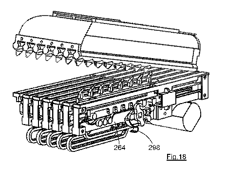
Fig.16 shows a perspective view of a second embodiment of hair styling device
according to
the present invention, in its open condition;
Fig.17 shows the drive mechanisms of the second embodiment of hair styling
device, with all
of the driving rails in their start positions; and
Fig.18 shows a view as Fig.17 but with the first driving rail part-way through
its range of
movement.
DETAILED DESCRIPTION
The hair styling device 10 comprises a body 12 with an integral handle 14.
Connected to the
body 12 is a closure part or lid 16. In this embodiment the closure part 16 is
pivotably mounted
to the body 12, but in other embodiments other mounting means for the closure
part are used.
Also, in this embodiment the closure part 16 is moved automatically, i.e. by
way of a motor (not
shown) as part of the sequence of operations of the device 10. In another
embodiment the
closure part is biased to its open position by a spring and is closed manually
by the user, the
closure part being held in its closed position by a latch which is
automatically released at the
end of the styling operation.
The body 12 carries a number of movable driving members or rails 20 (as better
seen in Figs 6-
10). In this embodiment there are six driving rails 20 but in other
embodiments there are more
or fewer driving rails as desired. Each of the driving rails 20 has a
series of raised driving
elements or pegs 22 (as better seen in Figs. 6 and 8-10). The driving rails 20
are in their start
or rest positions in Fig.1 and only the tips of the pegs 22 are visible.
The closure part 16 carries a number of forming members or rails 24. In this
embodiment there
are seven forming rails 24, i.e. one more than the number of driving rails 20.
Each of the
CA 03079372 2020-04-16
WO 2019/077338 PCT/GB2018/052981
13
forming rails 24 has a series of raised forming elements or pegs 26, some of
which are better
seen in Figs. 8-10.
A fixed guard rail 28 is located to each side of each of the driving rails 20.
The guard rails 28
are separated by a distance only slightly greater than the thickness of the
driving rails 20 so that
the driving rails 20 can slide between the neighbouring guard rails 28 whilst
minimising the
likelihood of hair entering between a guard rail 28 and a driving rail 20
where it might become
trapped. As shown in the representation of Fig.2, the forming rails 24 are
aligned with the guard
rails 28, so that the driving rails 20 are offset from the forming rails 24.
As is also shown in the
representation of Fig.2, the forming rails 24 are significantly narrower than
the guard rails 28 so
that the section of hair 36 can readily slide between the driving rails 20 and
forming rails 24
when the driving rails have moved into the hair-receiving regions 38 between
the forming rails
24 as explained below.
The body 12 has an end guide 30 and two side guides 32. It will be understood
that when the
closure part 16 is moved (pivoted) to its closed position only a small hair
entry gap remains at
each side of the device 10, with the closure part 16 defining the top of the
gap, the body 12
defining the bottom of the gap, and the guides 30 and 32 defining the opposing
sides of the gap.
The closure panel 16 can therefore largely enclose a chamber within which the
driving rails 22
and forming rails 24 are located and within which a section of hair can be
styled as described
below. The hair entry gap is large enough to permit hair to pass therethrough
and the closure
part 16 does not clamp any part of the hair against any part of the body 12
during use.
The section of hair 36 which is to be styled is shown schematically in Fig.1
approximately in the
orientation in which it will be introduced into the device 10. Thus, the
chosen section of hair 36
is oriented across the device as shown, and positioned between the body 12 and
the closure
part 16, and also between the opposing guides 30 and 32. It will be seen that
the guides 30
and 32 are tapered to assist the user in correctly positioning the section of
hair 36 between the
guides.
The device could have movable guide parts such as those described in
W02013/186547 in
order to prevent the user from inadvertently positioning the section of hair
36 beyond the gap
between the guides 30 and 32 (see also the movable guide parts of the second
embodiment
210 described below).
The section of hair 36 shown in Fig.1 is in the form of a "ribbon", i.e. it
has a much greater width
w than its depth d. Such a section of hair maximises the utility of the device
10, but the device
can if desired be used to style a "bundle" of hair, i.e. a section having a
similar depth and width
(or perhaps being approximately circular with a diameter somewhat less than
the dimension w).
Whilst it is desirable that the user spreads the chosen section of hair into a
ribbon form as
shown in Fig.1, it will be understood that a bundle of hair will in any event
be driven to spread
out along the rails 20, 24 as the closure part 16 is moved to its closed
position, so that
significant latitude in the configuration of the section of hair presented to
the device 10 is
available to the user.
Fig.2 represents a cross-section through a part of the device 10, and is
provided to show the
array of seven forming rails 24 and six driving rails 20, in the condition in
which the closure part
16 has been moved to its closed position. Fig.2 does not show the pegs 22, 26
so as to
CA 03079372 2020-04-16
WO 2019/077338 PCT/GB2018/052981
14
distinguish from the representations of Figs. 3-5, i.e. Fig.2 represents a
cross-section between
adjacent pegs for the driving rails 20 and the forming rails 24.
Fig.2 represents the start position of the driving rails 20, as is also seen
in Fig.1. In that position
the tips of the pegs 22 lie close to the top surface of the guard rails 28,
and the linear edges 40
of the driving rails 20 which lie between neighbouring pegs 22 (and which
linear edges are
shown in Fig.2 and also in Figs. 3-5) are located some distance below the top
surface of the
guard rails 28. The spacing between the guard rails 28 and driving rails 20 is
exaggerated in
Fig.2 for clarity, and as stated above in practice each driving rail 20 is a
close sliding fit between
the neighbouring guard rails 28 so as to minimise the likelihood that hair
will enter between a
driving rail and a guard rail.
Fig.2 also shows the driving rails 20 and forming rails 24 as being square-
cornered, primarily to
distinguish from the rounded pegs which are shown in Figs. 3-5. In practice
the corners of the
driving rails 20 and forming rails 24 will preferably be rounded so as to
avoid the hair being
forced to bend around a sharp corner as it is deformed into a wave.
Whilst the pegs 26 of the forming rails 24 are not shown in Fig.2, it will be
understood that they
project (downwardly as drawn) towards the guard rails 28. It can be arranged
that there is a
small gap between the tips of the pegs 26 and the guard rails 28 when the
closure part 16 is in
its closed position, and this is preferred so as to avoid the possibility that
hair can become
inadvertently trapped between a peg and guard rail, notwithstanding that the
tips of the pegs 26
are rounded so as to minimise the likelihood that hair will become trapped.
The pegs 22 of the driving rails 20 are also not shown in Fig.2, and it will
be understood that the
pegs 22 project (upwardly as drawn) towards the hair-receiving regions 38
between adjacent
forming rails 24. It is preferably arranged that when the closure part 16 is
in its closed position,
the pegs 22 overlap slightly with the pegs 26, and both sets of pegs engage
the length of hair
36. This has the effect of separating the ribbon or section of hair 36 into
separate smaller
sections (such as the separate smaller section 36a represented in Fig.3) as
the closure part 16
is closed. Because the driving members 20 are out of alignment with the
forming members 24,
there is no danger of the hair becoming clamped or trapped between the
overlapping pegs.
It will be understood that the section of hair 36 is laid between the driving
rails 20 and forming
rails 24 in the same manner as described in W02014/122442, i.e. across the
page from left to
right as drawn in Fig.2. When the device is operated, the driving rails 20
move in a first
direction D1, i.e. upwardly as drawn in Fig.2, each driving rail 20 moving
into a hair-receiving
channel 38, and driving the section of hair 36 into the respective hair-
receiving channels 38 to
adopt a wavy form.
Figs. 3-5 represent a part of a single driving rail 20 and a corresponding
part of a single forming
rail 24, in side view, i.e. perpendicular to the end view of Fig.2. In
particular, the direction of
view for Figs. 3-5 is from the right-hand side of Fig.2, looking substantially
along the length of
the individual hairs in the section of hair 36.
Fig.3 represents the start position of the driving rail 20. Fig.4 represents
the intermediate
position after the driving rail 20 has completed its movement in the first
direction Dl. Fig.5
represents the limit position after the driving rail 20 has completed its
movement in the second
direction D2.
CA 03079372 2020-04-16
WO 2019/077338 PCT/GB2018/052981
For ease of understanding, Fig.3 shows the pegs 22 and 26 as not overlapping
in the start
position, although as above described it is preferable for them to do so in
practice. As
explained above, overlapping pegs 22, 26 have the effect of separating the
section of hair 36
5 into a number of smaller sections 36a as the closure element 16 is moved to
its closed position.
Notwithstanding that the pegs 22, 26 are shown as not overlapping in Fig.3,
one of the resulting
smaller sections of hair 36a is represented in that figure. It will be
understood that the section of
hair 36 will in practice be separated into several smaller sections 36a
between neighbouring
pairs of pegs 22, 26, and that the smaller sections 36a are generally kept
separate by the pegs
10 22, 26 during the styling operation. To explain the operation of the device
it is necessary only to
explain the formation of a wave in one of the smaller sections of hair 36a in
one of the hair
receiving regions 38, it being understood that the formation of a wave in the
other hair receiving
regions, and in the other smaller sections of hair, is similar.
15 The first stage of movement of the driving rail 20 is upwardly (and
linearly) in the first direction
D1 to the position as drawn in Fig.4. During the first stage of movement, the
driving rail 20
enters the aligned hair-receiving channel 38 which is behind the forming
member 24 as drawn;
the pegs 22 of the driving rail 20 move past and beyond the pegs 26 of the
forming member 24.
Between each neighbouring pair of pegs 22 the driving member 20 has a linear
edge 40 and
between each neighbouring pair of pegs 26 the forming member 24 has a linear
edge 42.
During the first stage of movement the linear edges 40 move past and beyond
the linear edges
42.
The separate sections of hair 36a between each pair of neighbouring pegs 22,
26 are therefore
forced into a one-dimensional wave form. The portion 44a of the smaller
section of hair 36a
passes under the linear edge 42 of the forming rail 24 and the portion 44b of
the smaller section
of hair 36a passes over the linear edge 40 of the neighbouring driving rail
20, similarly to the
operation described in W02014/122442. Fig.4 shows the smaller section of hair
36a being
pressed from the circular cross-sectional shape into a more flattened cross-
sectional shape as it
is deformed into a wave (although the actual shape of the smaller sections of
hair 36a will likely
be more complex in practice).
The second stage of movement of the driving rail 20 is also linear and to the
right as drawn, in
the second direction D2, to the limit position as represented in Fig.5. During
this stage of
movement, the driving rail 20 moves along its hair-receiving channel 38
between neighbouring
forming members 24. The separate smaller sections of hair 36a are therefore
further deformed
as represented in Fig.5. In particular, the smaller section of hair 36a is
further deformed into a
wave in the second direction D2, with the portion 44a being restrained by its
engagement with
the side 46a of the peg 26 whilst the portion 44c is driven in the direction
D2 by its engagement
with the side 46b of the peg 22a.
Whilst only one of the separate smaller sections of hair 36a is represented in
Figs. 3-5, it will be
understood that a similar smaller section of hair is located between other
(and perhaps all of
the) pegs 22, 26 along the driving and forming rails 20, 24; the pegs 22, 26
thereby ensuring
that each of the separate smaller sections of hair is deformed to
substantially the same extent,
producing a uniform wave for the whole ribbon of hair 36. It will be
understood that the
deformation is substantially uniform regardless of the number of individual
hairs in the separate
smaller sections 36a, so that the user does not need to ensure that the
section of hair 36 has a
CA 03079372 2020-04-16
WO 2019/077338 PCT/GB2018/052981
16
consistent depth d or width w, nor that the sections of hair which are
successively styled by the
device are of consistent size.
The length of hair in each of the waves which are produced in the section of
hair 36 is
determined primarily by the length of the substantially linear portions 44d
between the portions
44a and 44c in the limit position of Fig.5 (the length of hair in each wave
being approximately
double the length of the substantially linear portions 44d). The length of the
substantially linear
portions 44d is determined largely by the distance through which the forming
members 20 move
in the second direction D2. In the representation of Fig.2 the forming member
20 moves in the
second direction D2 by a distance slightly greater than the spacing between
two adjacent pegs
22 but in practice the forming member 20 will move significantly further than
represented in
Fig.2, for example by a distance around five or six times the spacing between
neighbouring
pegs. It is expected that the movement of the driving members 20 in the
direction D2 will far
exceed the movement in the direction D1 in the commercial embodiments of the
device.
The section of hair 36 is therefore firstly separated into smaller sections
36a, and the smaller
sections of hair are then driven into a wave form in two different directions.
Whilst Figs. 3-5 represent the driving rail 20 as moving in two perpendicular
directions D1 and
D2, it will be understood that this is not necessary. Whilst it is
mechanically straightforward to
move the driving rail 20 in the second direction D2, i.e. along the hair-
receiving channel 38 (as
is explained in the drive mechanisms below), it is more mechanically difficult
to move the driving
rail 20 in the perpendicular direction D1 of Fig 4. Instead, therefore, as in
the drive mechanisms
described below, the driving rail 20 preferably moves from its start position
to its intermediate
position at an acute angle a. Despite the angled movement, the driving member
20 during its
first stage of movement has a component aligned with the perpendicular
direction through which
it moves into the hair-receiving channel 38, and that component of movement
causes the
section of hair to be pressed into the hair-receiving channel as required.
Also, the pegs 22,26
can maintain the separation of the smaller sections of hair 36a despite the
angled first stage of
movement of the driving members 20.
It will be appreciated that in embodiments according to some aspects of the
invention the
driving member can have a single stage of movement, for example in the
direction a. That is
not preferred, however, as it has been found that waves of larger amplitude,
and with a more
pleasing appearance, can be created by a two-stage movement, and with a
relatively large
movement in the second direction D2.
It will be understood from Fig.1 that initially only a relatively small
proportion of the total length
of the section of hair 36 lies within the device 10 in its start position.
During the first stage of
movement the relatively linear hairs shown in Fig.2 are deformed into a wave
form, which has
the effect of drawing more of the section of hair 36 into the device. Yet more
(or all) of the
section of hair 36 is drawn into the device during the second stage of
movement, as
represented by the relatively long substantially linear portion 44d.
As explained in
W02014/122442, the sequential movement of the driving members 20, with the
driving member
20 which is closest to the user's scalp moving first, minimises the tension
applied to the section
of hair 36 as it is drawn (progressively) into the device 10.
In addition, it can be arranged that the first driving member or rail, i.e.
that closest to the user's
scalp, moves relatively slowly during both its first and second stages of
movement. This will
CA 03079372 2020-04-16
WO 2019/077338 PCT/GB2018/052981
17
minimise the tension placed upon the hair and reduce the force exerted at the
user's scalp.
Subsequent driving members can move more rapidly, it being recognised that
tension in the
section of hair farther from the user's scalp will be less likely to be
exerted upon the user's
scalp.
The section of hair 36 is set in its wave form, ideally by the application of
heat. It will be
understood that the section of hair can be set with the driving members 20 in
their limit positions
as represented in Fig.5. That is not preferred, however, because the portions
44d are
substantially linear in that limit position. Notwithstanding that the section
of hair 36 may relax
somewhat if the driving members 20 are held in their limit positions, any
relaxation will be minor
and cannot be controlled. This has the result that the device will produce
relatively sharp waves
with substantially linear sections separated by relatively sharp bends. A more
aesthetically
pleasing wave can be created by ensuring that the smaller sections of hair 36a
relax into a more
natural curve.
This is achieved with the present invention by moving the driving rails 20
away from their limit
positions before the wave is set, i.e. towards the left as viewed in Fig.5.
The device can have a
defined retracted position such as that described below in relation to Fig.10,
or the driving rails
can move back to their start position before the wave is set, as desired.
The second direction D2 can be considered to be the hair-deforming direction
as most of the
deformation of the section of hair 36 occurs in that direction. Movement of
the driving rails 20 in
the second direction D2 therefore corresponds to movement in the hair-
deforming direction. It
will be understood that as the driving member 20 moves in the hair-deforming
direction the side
46b of the primary peg 22a engages the portion 44c and drives that portion in
the hair-
deforming direction to the limit position.
Subsequently, the forming member 20 is driven to reverse, i.e. to move in the
direction opposed
to D2. During this reverse movement, the side 46c of the neighbouring,
secondary, peg 22b will
engage the portion 44c of the smaller section of hair 36a. The section of hair
36 is not thereby
forced out of the device 10, but rather the portion 44c is driven to move
within the hair-receiving
channel 38, and is for example caused to ride up the secondary peg 22b away
from the linear
edge 40. It can be arranged that the pegs 22a,b are long enough to accommodate
the
complete reversal of movement along the direction opposed to D2, or it can be
arranged that
the hair-receiving channel 38 is somewhat deeper than the length of the pegs
22a,b so that the
portion 44c can pass over the top of the secondary peg 22b as the driving
member 20 moves to
the left as drawn. In any event, the reverse movement is sufficient so that
the smaller section of
hair 36a is no longer under any tension from the primary peg 22a, and is
ideally positively
pressed towards an unrestrained and more relaxed position by the secondary peg
22b. It is
arranged that the portions of hair 44a, 44c and 44d retain some or all of
their resilience and
notwithstanding the confines of the hair-receiving channels 38 the largely
unrestrained portions
of hair adopt the smoothest curl available within the hair receiving channel
38. In practice, only
the portions 44a passing underneath the linear sections 42 are relatively
fixed in position along
the smaller section of hair 36a, with the result that the remainder of the
smaller section of hair
36a forms a series of relatively smooth loops within the hair-receiving
channel 38. Since there
are multiple smaller sections of hair 36a within each of the hair-receiving
channels 38, all of
which have undergone a similar wave-forming operation, in practice the loop of
hair of one of
the smaller sections 36a overlies the loops of other smaller sections within
each of the hair-
receiving channels.
CA 03079372 2020-04-16
WO 2019/077338 PCT/GB2018/052981
18
The relaxation of the portions 44c,d, and the form of each of the resulting
loops, is dependent
upon the resilience of the section of hair 36, and is therefore enhanced if
the section of hair 36
is relatively cool during this hair-deforming stage of the operation. It is
thereby arranged that
the hair is set into its wavy form, ideally by the application of heat as
explained below, only after
the driving members 20 have reversed to the retracted (or start) position.
Now that the principles of operation of the device 10 have been described, the
specific
embodiments will be explained in more detail.
Fig.6 shows one driving rail 20 in its start position and a neighbouring guard
rail 28. A
longitudinal channel 50 is formed in the guard rail 28, which channel locates
a boss (not seen)
attached to the rear side of a guide member 52 and a boss (not seen) attached
to the rear side
of the guide peg 54. The respective bosses and the channel 50 restrain the
guide member 52
and guide peg 54 to longitudinal movement along the guard rail 28 (parallel
with the second
direction D2).
The forming rail 20 has two inclined guide channels 56, which contain the
respective bosses of
the guide member 52 and guide peg 54. The guide channels 56 are aligned at an
acute angle 13
to the second direction D2.
Connected to the other end of each of the bosses is a slide member or rack 60
as seen in Fig.7.
The guide member 52 and guide peg 54, and the rack 60, are therefore fixed to
move together
along the longitudinal channel 50, with the driving rail 20 and the guard rail
28 sandwiched
therebetween.
Figs. 6 and 7 show a single drive mechanism, i.e. a single driving rail 20 and
a single guard rail
28, from opposing sides. It will be understood that in a preferred hair
styling device there is a
number of (identical) driving rails 20 and a number of (identical) guard rails
28, with each driving
rail 20 being located between neighbouring guard rails 28. The drive
mechanisms for each
driving rail can be identical to that of Figs. 6 and 7 as described below.
In the assembled hair styling device 10 each drive mechanism interacts with
its neighbours to
produce the interconnected and sequential movement of the driving rails 20 as
explained in
detail below. In particular, the secondary pinion 62 shown in Fig.7 lies in
the same plane as
(and can engage) the tertiary pegs 58 of the guide member 52 of the
neighbouring drive
mechanism. Similarly, the latch 64 lies in the same plane as (and can engage)
the block 66 of
the driving rail 20 of the neighbouring drive mechanism.
It will be seen that the rack 60 carries a number of primary pegs 68 which are
aligned with, and
can engage, a primary pinion 70. The primary pinion 70 is the main drive
pinion and is driven to
rotate by a main drive motor (not shown) in the body 12.
The rack 60 also carries a number of secondary pegs 72 which are aligned with,
and can
engage, the secondary pinion 62. The secondary pinion 62 is passive in that it
is not driven by
a motor but is instead driven to rotate by the secondary pegs 72 of the
present rack 60, or by
the tertiary pegs 58 of the guide member 52 of the neighbouring drive
mechanism, as described
below.
CA 03079372 2020-04-16
WO 2019/077338 PCT/GB2018/052981
19
The latch 64 is mounted to the guard rail 28 and is spring-biased to rotate
anti-clockwise as
viewed in Fig.7. The latch 64 is engage by a cam 76. The primary pinion 70, a
secondary
pinion 62, a latch 64 and a cam 76 are mounted to the (fixed) guard rail 28,
and a similar set of
components is provided for each of the drive mechanisms.
A single main drive motor drives the primary pinion 70 of each of the drive
mechanisms to rotate
together. A single second drive motor (not shown) drives the cams 76 of each
of the drive
mechanisms to rotate together. Regardless of the number of drive mechanisms
which are
used in a particular hair styling device, only two motors are required to
actuate all of the driving
rails 20 to move sequentially as described in detail below.
Importantly, the cam 76 is not in the same plane as the primary pegs 68 (i.e.
it is nearer the
viewer than the primary pegs 68 in the orientation of Fig.7). The body of the
cam 76 can
therefore rotate through 360 from the position shown without engaging or
moving the primary
pegs 68.
The cam 76 of the first driving rail 20 differs from the cams of the other
driving rails in having an
initiating element or finger (not seen) on its rear surface. The initiating
finger extends into the
same plane as the primary pegs 68 of the first drive mechanism and is
positioned to engage the
primary pegs 68 as the cam 76 rotates, as described below. The cam 76 is
therefore a latch
release cam for each of the drive mechanisms, and is also an initiating
mechanism for the first
drive mechanism.
The sequence of operations for a hair styling device comprising a plurality of
drive mechanisms
as shown in Figs.6 and 7 will now be described, starting from the position in
which all of the
driving rails 20 are in their start or rest position as represented in Figs.6
and 7. In that position,
as seen in Fig.7, the primary pegs 68 do not engage the primary pinion 70.
Firstly, the cam 76 is driven by a second drive motor to rotate through 360
in the anti-clockwise
direction as viewed in Fig.7. During this rotation, the initiating finger
which is carried by the first
cam 76 engages one of the primary pegs 68 of the first rack 60 and pushes the
rack 60 in the
direction D2. Because the cams 76 of the other drive mechanisms do not have an
initiating
finger their corresponding rotation causes no movement of the second, third
etc. racks 60. The
initiating finger pushes the (first) rack 60 sufficiently far to the left as
viewed in Fig.7 so that the
leading primary peg 68 engages the teeth of the primary pinion 70.
The primary pinion 70 is then driven to rotate anti-clockwise as viewed in
Fig.7 whilst engaging
the primary pegs 68. The first rack 60 is therefore driven further in the
direction D2.
As the rack 60 moves in the direction D2 the bosses which are connected to the
guide member
52 and guide peg 54 move relative to the respective angled guide channels 56
of the driving rail
20. It will be seen from Fig.6 that the driving rail 20 has a centre slot 78,
and that the drive
shafts 80, 82 which interconnect all of the primary pinions 70 with the main
drive motor, and
which interconnect all of the cams 76 with the second drive motor,
respectively, pass through
the centre slot 78. When viewed in the orientation of Fig.6, the shaft 82
limits the rightwards
movement of the driving rail 20 and the angled edge 84 of the centre slot 78
causes the
longitudinal movement of the rack 60 to be converted into an angled (upwards
as viewed)
movement of the driving member 20.
CA 03079372 2020-04-16
WO 2019/077338 PCT/GB2018/052981
It will be understood that the direction of movement Dl of the driving rail 20
during this first
stage of movement corresponds to the angle of the edge 84, which is around 600
in this
embodiment.
5 The centre slot has an extension 86 which is aligned with the direction D2.
It will be understood
that, when the shafts 80, 82 enter the extension 86, the driving rail 20 moves
solely in the
direction D2.
The two-stage movement of the driving rail 20 is therefore caused by the
shaping of the centre
10 slot 78, with the driving rail 20 following a defined path as the shafts
80, 82 move along the
respective edges of the centre slot 78 as the driving rail 20 is driven by the
motion of the rack 60
along the longitudinal channel 50. In particular, because the edge 84 is
linear, and because the
extension 86 is linear, the path of movement of the driving member 20 in this
embodiment is
linear during both its first and second stages of movement.
The primary pinion 70 continues to rotate to drive rack 60 in the direction D2
by driving against
the primary pegs 68. During this movement, the secondary pegs 72 are driven
past the
secondary pinion 62. Because there are fewer secondary pegs 72 than primary
pegs 68,
continued movement of the rack 60 causes the secondary pegs to disengage from
the
secondary pinion 62 before the rack 60 reaches the end of its movement in the
direction D2.
As the rack 60 of the first driving mechanism approaches the end of its
movement in the
direction D2, the tertiary pegs 58 of the guide member 52 connected to that
rack will engage the
secondary pinion 62 of the neighbouring (second) drive mechanism. The second
driving rail 20
is initially in its start position similar to that of Fig.6, so that its
secondary pegs 72 are already
engaged with its secondary pinion 62. Consequently, as the primary pinion 70
continues to
move the first rack 60 forwards, the rotation of the secondary pinion 62 of
the second drive
mechanism initiates the movement of the second driving rail 20. The first and
second racks 60
are temporarily driven in the direction D2 simultaneously due to their both
engaging the
secondary pinion 62 of the second drive mechanism.
Just before the first driving rail 20 reaches its limit position, its primary
pegs 68 become
disengaged from its primary pinion 70. However, the second rack 60 is then
moving forwards,
driven by its primary pinion 70, and the secondary pegs 72 of the second rack
continue to rotate
its secondary pinion 62. Rotation of the secondary pinion 62 of the second
drive mechanism
drives the tertiary pegs 58 of the first rack 60, causing the first rack 60 to
continue to move to its
limit position despite the disengagement of its primary pegs 68 from its
primary pinion 70.
The first driving rail 20 has at this point followed the path determined by
the centre slot 78 to
arrive at its limit position. During the final stage of forwards movement the
block 66 of the first
driving rail 20 passes the spring-biased latch 64 of the second drive
mechanism. The latch 64
temporarily secures the first driving rail 20 in its limit position.
As the second rack 60 moves in the direction D2 its primary pegs 68 engage
with its primary
pinion 70 and rotation of the primary pinion 70 drives the second rack 60 to
move, and
consequently drives the second driving rail 20 to move, along a similar path
to that of the first
driving rail. The limit position of the first driving rail 20a is represented
in Fig.8. This figure also
shows the second driving rail 20b undergoing its first stage of movement in
the first direction
Dl.
CA 03079372 2020-04-16
WO 2019/077338 PCT/GB2018/052981
21
The sequence continues to move all of the driving rails 20 sequentially,
repeating the same
interaction from one driving rail to the next until all the driving rails are
latched in their limit
positions. Fig. 9 shows a subsequent stage in the operation of the device, in
which all of the
driving rails 20 have reached their limit position. Only the nearest driving
rail 20 is visible in
Fig.9 because the other driving rails are identically formed and are perfectly
aligned behind it. It
will be understood that the maximum deformation of the section of hair 36
occurs when all of the
driving rails 20 are at their limit position.
If desired, the driving rails 20 can all remain latched in their limit
positions during the hair styling
operation, i.e. they can be retained there until the wave has been set.
Preferably, however,
when the final driving rail has been latched into its limit position the
sequence of operations
continues immediately to reverse all of the driving rails together and thereby
to reduce the
tension in the length of hair and permit the formation of a more natural wave.
In this
embodiment, all of the driving rails 20 move together back in a direction
opposed to the second
(or hair-deforming) direction D2, to the retracted position as shown in
Fig.10. As the tension is
relieved the separate smaller sections of hair 36a relax into more natural-
looking waves within
the hair-receiving regions 38 as described above.
To reverse the movement of the driving rails, the second drive motor drives
all of the cams 76 to
rotate together in an anti-clockwise direction as viewed in Fig.7, releasing
all the latches 64 from
their respective blocks 66 simultaneously. This unlocks all of the driving
rails 20 to allow them
to reverse (in the direction opposed to D2).
As each of the cams 76 rotates, it also engages the block 66 of the
neighbouring driving rail 20.
The cams 76 push against the respective block 66 and thereby push each of the
driving rails 20
to reverse (together).
As the driving rails 20 reverse, their racks 60 move sufficiently in the
direction opposed to D2 to
engage the leading primary peg 68 with the respective primary pinion 70. When
the leading
primary peg 68 of each rack 60 is fully engaged with its respective primary
pinion 70, the cams
76 return back to their rest position as shown in Fig.7.
The main drive motor then rotates the primary pinions 70 to drive all the
racks 60, and
consequently all of the driving rails 20, to reverse. The driving rails 20
move a predetermined
distance in the direction opposed to D2 to control the size of the wave, i.e.
the reverse rotation
of the primary pinions 70 is paused after a chosen number of rotations (or
partial-rotations) to
stop all of the driving rails 20 in a defined retracted position.
The driving members 20 can remain in the retracted position of Fig.10 whilst
the wave is set. In
an alternative arrangement, the driving rails simply pass through the
retracted position of Fig.10
on their way back to their start positions, the length of hair being set only
after the driving rails
have been retracted back to their start positions. It will be understood that
the section of hair 36
can more freely move in the hair receiving channels 38 when the driving
members 20 have
been moved back to their start positions (and the pegs 22 are no longer
projecting into the hair-
receiving channels 38). The degree of retraction can therefore be used to vary
the wave which
is formed in the length of hair, with more retraction giving more freedom to
the section of hair 36
and generally providing a more natural looking wave.
CA 03079372 2020-04-16
WO 2019/077338 PCT/GB2018/052981
22
When the driving rails 20 have been moved back to their desired retracted
positions one or
more heaters are actuated to heat the hair sufficiently to form the desired
wave. When the hair
has been heated sufficiently, the heaters are turned off and the heated
components are allowed
to cool to a lower idle temperature. Ideally the section of hair is retained
in the device 10 as the
components are cooled; this helps to form the desired wave by allowing the
hair to cool whilst
the wave form is maintained.
When the heating and cooling cycle is complete the primary pinions 70 act
against the primary
pegs 68 of each rack 60 simultaneously to drive all the racks, and
consequently all of the driving
rails 20, back to their start position. It will be understood that the racks
60 are driven to reverse
until each rotating primary pinion 70 becomes disengaged from the trailing
primary peg 68. In
that position, the guide member 52 engages a resilient latch or clip 88 in
order to temporarily
secure the driving members 20 in their start position.
The drive system of the device 10 can therefore actuate multiple driving rails
20 to move along
a predetermined path in a two-stage movement, with the driving members 20
moving
sequentially to their limit positions. The drive system utilises only two
motors so as to minimise
the weight of the device 10 and has means to link the movement of one driving
rail to its
neighbouring driving rail. In an alternative arrangement, the movement of each
driving rail 20
can be individually controlled, perhaps by one or more separate motors for
each driving rail, if
that is desired. Also, whilst the driving rails 20 move in the (angled)
direction D1 during their
first stage of movement, other drive systems may cause the driving rails to
move in a direction
perpendicular to the second direction D2 during the first stage of movement.
It will be understood that, when the shafts 80, 82 reach the bottom end (as
viewed) of the edge
84 of the centre slot 78, the driving rail 20 has reached its intermediate
position, i.e. it has
reached the end of its first stage of movement and the end of its movement in
the first direction
Dl. In that intermediate position the pegs 22, and also the linear edges 40
between the pegs
22, have moved into the hair-receiving channel 38 as represented in Fig.4.
It will also be understood that, as the driving rail 20 moves in the direction
D2 during its second
stage of movement, the pegs 22 move along their respective hair-receiving
channel 38 as
represented in Fig.5.
The sequential movement of the driving members 20 results in the gradual
introduction of the
length of hair into the device 10. In the representation of Fig.2, the end 48
of the section of hair
36 represents the scalp end of the section of hair. The free end of the
section of hair 36
extends beyond the right-hand edge of the page. It is arranged that the device
10 is oriented so
that the driving rail 20 closest to the scalp end 48 moves first, with the
neighbouring driving
member moving second and so on. The scalp end of the section of hair 36 is
relatively fixed
and so movement of the first driving rail 20 causes more of the section of
hair to be drawn in
from the free end. Yet more of the section of hair 36 is drawn in as each
subsequent driving rail
20 is moved as above explained, and ideally the free end of the section of
hair 36 is drawn into
the device before the last of the driving members 20 has reached its limit
position (so that
waves are imparted along the full length of the chosen section of hair). The
number of driving
rails, and the distance the driving rails move (particularly in the direction
D2) can be chosen to
ensure that a wave can be imparted to a section of hair up to a desired
length.
CA 03079372 2020-04-16
WO 2019/077338 PCT/GB2018/052981
23
Figs. 8-10 show artificial positions in which the driving members 20 have
moved whilst the
closure part 16 is open, for the purposes of understanding. In practice, it is
preferably arranged
that the control system will not actuate the driving members 20 to move unless
the closure part
16 is in its closed position.
As above stated, the device 10 includes electrical heating elements (not
seen). A heating
element can for example be located in each of the guard rails 28, and/or in
each of the forming
members 24. Alternatively, hot air can be blown along the hair-receiving
channels to heat the
section of hair and set the wave. Typically, a temperature of around 200 C
will be used to set
the wave form in the section of hair, but it is recognised that different hair
types will require
different styling temperatures, and also a lower/higher temperature can be
used together with a
longer/shorter styling duration.
The closure part 16 can be opened (automatically) after a period of time, the
period being
determined by the user or preferably being predetermined as required to set
the wave form.
However, it is preferable to cool the section of hair 36 before it is removed
from the device 10,
so as to seek to minimise the subsequent loss of the wave form and also to
reduce the pain
caused in the event that a user inadvertently touches a heated part of the
opened device.
In the first embodiment of hair styling device 10, an airflow generator (not
seen, but ideally a fan
or impeller) is mounted in the body 12 to pump ambient air into the device 10
to cool the (styled)
section of hair 36 within the device. Fig.1 shows grilles at the end of the
body 12 and closure
part 16 through which ambient air is admitted (or expelled, as desired), there
being one or more
corresponding grilles at the other end of the body. Desirably, the styled
section of hair is cooled
to a temperature of around 100 C before the closure part 16 is opened and the
styled section of
hair is removed. It will be understood that moving the driving members 20 back
to their start
position before the airflow generator is actuated will facilitate airflow
though the device, and in
particular air flow along the hair-receiving channels 38.
It will be understood that the use of an airflow generator is optional and
alternative
embodiments can simply switch off the heat and rely upon radiation or
convection to cool the
heated parts of the device and the styled section of hair 36 before it is
removed.
It is a benefit of a dual temperature regime that the next section of hair 36
can be inserted into a
relatively cool device 10, the relatively cool surfaces being less likely to
damage the section of
hair as it is deformed, and also maintaining resilience in the section of hair
as it is deformed.
Accordingly, the section of hair only experiences the styling temperature
(e.g. around 200 C)
when it has been deformed into a wavy form and subsequently allowed to relax
in the hair-
receiving channels 38.
It will be understood that the styling (high) temperature can be adjusted by
the user in order to
vary the wave which is formed. Similarly, the duration of the styling process
for each section of
hair can be adjusted to vary the wave which is formed.
In the embodiment shown the movement of the driving members is controlled by
the longitudinal
channel 50, by the guide channels 56, and by the opening or central slot 78,
with the extent of
movement in the first direction D1 in particular being determined by the
length of the shorter
guide channel 56 and the corresponding length of the edge 84 of the central
slot 78. In
alternative embodiments the movement of the driving members 20 in both
directions D1 and D2
CA 03079372 2020-04-16
WO 2019/077338 PCT/GB2018/052981
24
can be controlled, separately, thereby enabling the user to adjust the
distance moved in each of
those directions so as to vary the form of the wave. It is nevertheless
desirable that each
driving member of a hair styling device move by the same distance in both of
the respective
directions D1 and D2 so that a uniform wave is formed along the section of
hair 36, even if each
driving member is independently controlled and actuated.
The control system for the drive mechanisms, and in particular the control
system for the main
drive motor driving the primary pinions 70 and second drive motor driving the
cams 76, is
mounted in the body 12. The control system can measure the load upon the main
drive motor
and if the load exceeds a predetermined threshold it can stop the motor and
open the closure
part 16, it being recognised that a motor overload is likely to occur either
if too much hair has
been inserted into the device, or if the section of hair has become entangled.
Once the closure
part 16 has been opened it is expected that the user will be able to extract
the section of hair
and re-start the process.
The control system can also communicate with sensors positioned to detect
misplaced hair.
For example, the guides 30 and/or 32 can carry sensors (perhaps optical
sensors) adapted to
detect the presence of hair which might become inadvertently trapped between
one of those
guides and the closure part 16. The control system can prevent movement of the
driving
members 20 and issue a warning signal to the user if misplaced hair is
detected.
Whilst the drawings show a specific embodiment having elongate driving rails
20 and similarly
elongate forming rails 24, it will be understood that the rails could be
replaced by much shorter
driving and forming members, each perhaps having just two pegs 22,26. Such a
device would
be suitable for styling a bundle of hair rather than a ribbon of hair but
could nevertheless benefit
from some of the advantages of the invention.
A second embodiment of drive mechanism is shown in Figs. 11-15. This
embodiment differs
structurally from the first embodiment of drive mechanism of Figs.6-10, and
also in terms of its
method of operation, as described below. Whilst the differences are described
below, it will be
understood that there are many similarities (including for example the general
principle of
operation described in relation to Figs. 3-5); a number of drive mechanisms
according to the
second embodiment could for example be used in a hair styling device similar
to that of Fig.1.
Firstly, the pegs 122 of the driving rails 120 are significantly shorter (in
the direction
perpendicular to the second direction D2) than the pegs 22 (in this embodiment
the pegs 122
have a height of 6 mm as compared to a height of 15 mm for the pegs 22). Also,
the distance
which the driving rails 120 move perpendicular to the second direction D2 is
reduced. Both of
these structural modifications reduce the dimension of the drive mechanism
perpendicular to
the second direction D2, and thereby enable a reduction in the overall size of
the hair styling
device.
Secondly, the pegs 122 are angled in the second direction D2, and are more
sharply pointed.
These structural modifications help to ensure that the pegs 122 effectively
capture all of the
individual hairs in the section of hair being styled, and (further) reduce the
likelihood of any
individual hairs becoming trapped by parts of the hair styling device in use.
Thirdly, the side 146c of each of the pegs 122 is angled so as to cause the
length of hair to be
more positively pushed away from the linear edge 140 of the driving rail 120
when the
CA 03079372 2020-04-16
WO 2019/077338 PCT/GB2018/052981
movement of the driving rail is reversed. This structural modification
encourages the length of
hair to relax into a more natural wave as the driving rails are reversed.
Fourthly, the second embodiment of drive mechanism does not include a
secondary pinion, nor
5 therefore secondary pegs or tertiary pegs. The interactions between
neighbouring drive
mechanisms are provided by other parts of the mechanism as described below.
Fifthly, the shape and location of the latch 164 has been altered, which also
reduces the
dimension of the drive mechanism in the direction perpendicular to the second
direction D2 and
10 enables a reduction in the size of the hair styling device.
One major similarity between the first and second embodiments of drive
mechanism is that
parts of each drive mechanism are located to opposing sides of a guard rail.
In particular, the
driving rail 20, 120 with its pegs 22, 122 is located to one side of the guard
rail 28, 128 and is
15 connected to a rack 60, 160 at the other side of the guard rail. The
connection is made by way
of bosses which pass through an elongate longitudinal channel 50, 150 in the
guard rail. The
bosses slide along the channel 50, 150 to provide support and guidance to the
driving rails 20,
120 during their movement. Also, there are multiple drive mechanisms and some
of the
componentry of the first drive mechanism interacts with componentry of the
second drive
20 mechanism (and so on) so that the movements of the respective driving rails
can be linked.
This latter commonality minimises the number of motors required in a practical
device, as above
explained.
Other structural differences, and the resulting changes to the operation of
the drive
25 mechanisms, are described in the sequence of operations below, again
starting from the
position in which all of the driving rails 120 are in their start position as
represented in Figs.11
and 14. In that position, as seen in Fig.11, the primary pegs 168 do not
engage the primary
pinion 170.
Initially, the cam 176 is rotated in the clockwise direction as viewed in
Fig.11. During this
rotation, the extra lobe 190 which is carried by the cam 176 of the first
drive mechanism acts as
an initiating element and engages one of the primary pegs 168 of the first
rack 160 and pushes
the rack 160 in the direction D2). The cams 176 of the other drive mechanisms
do not have an
extra lobe and so their corresponding rotation causes no movement of the
second, third etc.
racks 160. The extra lobe 190 pushes the (first) rack 160 sufficiently far in
the direction D2 so
that the leading primary peg 168 engages the teeth of the primary pinion 170.
The primary pinion 170 is then driven by a main drive motor (not shown) to
rotate clockwise as
viewed in Fig.11 whilst engaging the primary pegs 168. The rack 160 is
therefore driven in the
direction D2.
As with the first drive mechanism described above, the two-stage movement of
the driving rail
120 is caused by the shaping of the centre slot 178 (see Figs. 14 and 15),
i.e. the drive shafts
180, 182 of the respective main drive motor and second drive motor (not shown)
are fixed in
position and cause the driving rail 120 to move in the directions D1 and D2
following the shape
of the centre slot 178, and driven by the motion of the rack 160 along the
longitudinal channel
150.
CA 03079372 2020-04-16
WO 2019/077338 PCT/GB2018/052981
26
The primary pinion 170 continues to rotate to drive rack 160 in the direction
D2 by driving
against the primary pegs 168. As the rack 160 moves forwards, the guide member
152 of the
first rack 160 will engage the edge 172 of a raised section of the
neighbouring (second) drive
mechanism. It will be understood that the raised section stands proud of the
remainder of the
rack 160, and so is nearer to the viewer than the remainder of the rack 160 as
viewed in Fig.11.
The second driving rail 120 is initially in its start position similar to that
of Fig.11. Consequently,
as the guide member 152 of the first drive mechanism moves in the direction D2
it initiates the
movement of the second drive mechanism by pushing the edge 172 and
consequently the
second rack 160 in the direction D2. The first and second racks 160 are
temporarily driven
forward simultaneously due to the interengagement of the guide member 152 and
edge 172.
The trailing end 192 of the rack 160 lies in the same plane as the latch 164.
As the first driving
rail 120 moves towards its limit position, the trailing end 192 passes the end
of the inclined edge
194 of the latch 164 (see Fig. 13). The latch is spring biased anti-clockwise
as viewed in Figs.
11 and 12, and as the trailing end 192 of the rack 160 moves past the inclined
edge 194 the
latch rotates a few degrees anti-clockwise to move behind the trailing end
192, as shown in
Fig.12. The spring-biasing of the latch 164, and the angling of the inclined
edge 194 act to
move the rack 160 further in the direction D2 to its limit position,
notwithstanding that the
primary pegs 168 have become disengaged from the primary pinion 170 as also
seen in Fig.12.
The latch 164 therefore temporarily secures the first driving rail 120 in its
limit position as shown
in Figs. 12 and 15.
As the second rack 160 moves in the direction D2 its primary pegs 168 engage
with its primary
pinion 170 and rotation of the primary pinion 170 drives the second rack 160
to move, and
consequently drives the second driving rail 120 to move, along a similar path
to that of the first
driving rail. The sequence continues to move all of the driving rails 120
sequentially, repeating
the same interaction from one driving rail to the next until all the driving
rails are latched in their
limit positions.
To reverse the movement of the driving rails, the second drive motor rotates
the cams 176 in an
anti-clockwise direction as viewed in Fig.12, releasing all the latches 164
simultaneously. This
unlocks all of the driving rails 120 to allow them to reverse. Also, as each
of the cams 176
rotates, it engages a peg 166 of the rack 160. The cams 176 push against the
respective pegs
166 and thereby push each of the driving rails 120 to reverse (together). As
the driving rails 120
reverse, their racks 160 move sufficiently to engage the primary pegs 168 with
the respective
primary pinions 170. The primary pinions 170 then rotate (anticlockwise as
viewed in Fig.11) to
drive all the racks 160, and consequently all of the driving rails 120, in the
direction opposed to
D2.
As with the first embodiment, all of the driving members 120 may be moved to a
retracted
position at which heat is applied to set the wave in the section of hair;
alternatively, the driving
rails 120 can be moved directly back to the start or rest position.
At the end of the cycle, each of the racks 160 is driven to reverse until each
rotating primary
pinion 170 becomes disengaged from the primary pegs 168 as seen in Fig.11. In
that position,
the peg 166 of the rack 160 has passed the spring-biased projection 188 of the
latch 164, the
resilience of the projection 188 temporarily securing the driving rail 120 in
its start position.
CA 03079372 2020-04-16
WO 2019/077338 PCT/GB2018/052981
27
Whilst both of the drive mechanisms described above incorporate two motors, it
will be
understood that (apart from the initiating movement of the first driving rails
20, 120) all of the
driving rails 20, 120 are driven from their start positions to their limit
positions by a single main
drive motor. Other embodiments can exclude the second motor of the above-
described
embodiments so that the drive systems include only a single motor. For
example, the initiating
element could comprise an extra tooth of the rack of the first driving rail so
that the rack of the
first drive mechanism remains engaged with its pinion in the start position
(thereby avoiding the
requirement of the second motor to initiate the movement of the first driving
rail).
Also, the latches which temporarily secure the driving rails in their limit
positions could be
excluded, with the respective (rotating) pinions maintaining the driving rails
in their limit
positions (thereby avoiding the requirement for the second motor to actuate
the latch releasing
mechanisms). Even in embodiments in which the driving rails are latched in
their limit positions,
however, other means (such as one or more solenoids for example) may be
provided to release
the latch mechanisms and to move the driving rails away from their limit
positions so as to
engage the main drive motor.
In another alternative drive system incorporating only a single motor, the
last drive mechanism
could exclude a latch mechanism, and instead could incorporate a latch release
mechanism for
the latches of the other drive mechanisms. In such an arrangement, the first,
second etc. up to
the penultimate driving rail could be latched into its respective limit
position, and the latch
mechanisms could be released (and all of the driving rails driven away from
their limit positions),
by movement of the final driving rail as it approaches its limit position.
In yet another alternative drive system incorporating only a single motor, the
single motor may
be connected to separate drive systems, one of the drive systems rotating the
pinions 70, 170
and the other drive system rotating the cams 76, 176. Suitable control systems
can be
incorporated to connect/disconnect the motor from the separate drive systems
during different
stages of operation.
Fig.16 shows a second embodiment of hair styling device 210 comprising a body
212 with an
integral handle 214. Connected to the body 212 is a closure part or lid 216.
This embodiment
has a two-part handle 214, the closure part 216 being connected to a second
handle part 214a
permitting the user to move the closure part 216 to its closed position by
pressing the handle
parts together, in known fashion. The handle parts are preferably biased apart
to their open
position as shown in Fig.15. The handle 214 of this second embodiment is
substantially aligned
with the longitudinal axis of the driving rails 220 so that the handle has a
"wand-like" orientation,
as opposed to the "pistol grip" orientation of the first embodiment.
Another significant difference over the first embodiment described above is
that the guides 230
completely span the distance between the body 212 and the closure part 216 in
the open
condition shown, and thereby prevent any hair being inserted into the device
in a position where
it may become trapped. The guide parts 230 are mounted to project (downwardly
as viewed)
from the closure part 216 and as the device is closed the guide parts move
(further) into
cooperating recesses in the body 112. In an alternative embodiment the guide
parts are
mounted to project (upwardly) from the body and as the device is closed the
guide parts move
(further) into cooperating recesses in the closure part.
CA 03079372 2020-04-16
WO 2019/077338 PCT/GB2018/052981
28
The hair styling device 210 could have a drive system incorporating the first
embodiment of
drive mechanism of Figs. 6-10, or the second embodiment of drive mechanism of
Figs. 11-15,
as desired.
The drive system is shown in Figs. 17 and 18 separate from the surrounding
housing parts.
The drive system is a slightly modified version of the second embodiment of
drive mechanism,
which is preferred because of its reduced dimension perpendicular to the
second direction D2.
The drive mechanisms of the hair styling device 210 are very similar to the
second embodiment
of drive mechanism described above and their operation is the same and will
not be repeated.
However, it is apparent from Figs. 17 and 18 that much of the material
surrounding the central
slot 278 has been removed to save material and weight. Also, the latch 264
incorporates a
metallic resilient element 296 in place of the moulded plastic resilient
element 196 of the second
embodiment of drive mechanism (it will be understood that a metal spring is
more likely to
maintain its resilience over time at the temperatures expected to be
encountered by the latch).
Furthermore, the latch 264 has a metallic element 298 which is engaged by the
cam 276.