Note : Les descriptions sont présentées dans la langue officielle dans laquelle elles ont été soumises.
VALVE CONTROL AND/OR LUBRICATION SYSTEM
FIELD OF THE DISCLOSURE
The present disclosure is directed to a system for controlling and/or
lubricating
a plurality of flow control valves, such as valves of a type which are used on
frac
trees at a well fracturing site. In particular, the disclosure is directed to
a system
which communicates the hydraulic fluid used to actuate the valves and/or the
lubricant used to lubricate the valves to the frac trees over a single hose
set, thereby
greatly reducing the number of hydraulic fluid and lubricant hoses which
otherwise
would be required at the frac site.
BACKGROUND OF THE DISCLOSURE
Typical prior art well fracturing operations employ a number of frac trees
which
each include a plurality of hydraulically operated valves. These valves
include valve
actuators which are operated by hydraulic pressure that is often supplied by a
centrally located hydraulic pressure unit (HPU). Each valve actuator normally
comprises two piston chambers which are each connected to the HPU via a
respective hydraulic hose. Thus, depending on the number of frac trees which
are
used at the frac site and the number of hydraulically operated valves which
each frac
tree employs, dozens of hydraulic hoses may be required to connect all of the
valve
actuators with the HPU. However, such a large number of hoses are very costly,
can
be time consuming to install and pose trip hazards to personnel at the frac
site.
Also, due to the relatively high pressures employed in fracking operations, a
possibility exists that the fracking fluid will enter the valve cavity and
interfere with the
ability of the valve to seal properly. Consequently, the cavity is usually
filled with a
lubricant, such as grease. The lubricant not only forms a barrier to prevent
the
ingress of fracking fluid into the cavity, but also cleans and coats the
sealing surfaces
of the valves. However, over time the lubricant tends to break down and become
depleted. As a result, additional lubricant must periodically be injected into
the cavity;
1
Date Recue/Date Received 2020-04-28
and the act of pumping in the grease flushes fracking fluid and debris from
the valve
cavity.
In the prior art, the lubricant is often injected manually by an operator
using a
grease pump or "grease gun". However, this is a time consuming process and
exposes the operator to the dangers inherent in the areas surrounding the frac
trees.
As an alternative, the valves may be connected to a centralized lubrication
system.
In such a system, individual lubricant hoses are used to connect each
lubricant fitting
on the valve to a centralized lubrication system. Once again, however, this
arrangement requires the use of a large number of hoses, which is costly, can
be
time consuming to install and pose trip hazards to personnel at the frac site.
SUMMARY OF THE DISCLOSURE
In accordance with the present disclosure, these and other issues in the prior
art are addressed by providing a valve control and/or lubrication system for
operating
and/or lubricating a plurality of valves which are mounted on a number of
christmas
trees. Each valve comprises a hydraulic actuator which is operated by
hydraulic
pressure from a hydraulic pressure source and/or a lubricant inlet which is
connected
to an interior portion of the valve which is configured to receive a lubricant
from a
lubricant source. The system includes a plurality of control units, each of
which is
associated with a respective valve and each of which comprises at least one of
a
hydraulic pressure line which is connectable to the hydraulic pressure source
and a
lubricant line which is connectable to the lubricant source. Each control unit
further
comprises at least one of a hydraulic port and a lubricant port, and the
system further
comprises at least one of a hydraulic conduit which is connected between the
hydraulic port and the hydraulic actuator and a lubricant conduit which is
connected
between the lubricant port and the lubricant inlet. Each control unit also
includes at
least one of a hydraulic activation means for selectively connecting the
hydraulic
pressure line to the hydraulic port and a lubricant activation means for
selectively
connecting the lubricant line to the lubricant port. In operation, each
control unit is
operable to selectively connect the hydraulic pressure source to the hydraulic
2
Date Recue/Date Received 2020-04-28
actuator to thereby operate the valve and/or to selectively connect the
lubricant
source to the lubricant inlet to thereby communicate lubricant into the
interior portion
of the valve.
In accordance with one aspect of the disclosure, the hydraulic activation
means comprises an electrically, hydraulically or pneumatically operated first
valve
which is connected between the hydraulic pressure line and the hydraulic port.
The
first valve may comprise, e.g., a solenoid operated valve.
In accordance with another embodiment of the disclosure, each control unit
also comprises a hydraulic return line which is connectable to the hydraulic
pressure
source and first and second hydraulic ports which are connected via respective
first
and second hydraulic conduits to the hydraulic actuator. In operation, the
hydraulic
activation means is operable to selectively connect the hydraulic pressure and
return
lines to the hydraulic actuator to thereby operate the valve. In this
embodiment, the
hydraulic activation means may comprise an electrically, hydraulically or
.. pneumatically operated first valve which is connected between the hydraulic
pressure
and return lines and the first and second hydraulic ports. The first valve may
comprise, e.g., a solenoid operated directional control valve.
In accordance with yet another embodiment of the disclosure, the lubricant
activation means comprises a first valve which is connected between the
lubricant
.. line and the lubricant port.
In accordance with a further embodiment of the disclosure, the lubricant
activation means comprises a lubricant pump which is connected between the
lubricant line and the lubricant port. In accordance with one aspect of the
disclosure,
the lubricant pump comprises a first cylinder which is alternately connectable
to the
.. hydraulic pressure and return lines and a second cylinder which is
connected to the
lubricant line. In accordance with another aspect of the disclosure, the
lubricant
activation means further comprises an electrically, hydraulically or
pneumatically
operated first valve which is connected between the first cylinder and the
hydraulic
pressure and return lines, and wherein the first valve is configured to
alternately
3
Date Recue/Date Received 2020-04-28
connect the first cylinder to the hydraulic pressure and return lines to
thereby operate
the lubricant pump.
In accordance with another embodiment of the disclosure, the valve comprises
first and second lubricant inlets, each control unit comprises first and
second
lubricant ports which are connected to the lubricant inlets by respective
first and
second lubricant conduits, and the lubricant activation means further
comprises an
electrically, hydraulically or pneumatically operated second valve which is
connected
between the lubricant pump and the first and second lubricant ports. At least
one of
the first and second valves may comprise a solenoid operated directional
control
valve.
In accordance with one aspect of the disclosure, each control unit comprises a
controller which is configured to operate the hydraulic activation means
and/or the
lubricant activation means.
In accordance with another aspect of the disclosure, each control unit further
comprises means for enabling an operator to manually operate the hydraulic
activation means and/or the lubricant activation means.
In accordance with yet another aspect of the disclosure, the system may
comprise a control computer which is located remotely of the christmas trees
and is
configured to control the operation of the controllers.
In accordance with a further aspect of the disclosure, the system may
comprise means for identifying to the control computer the valves to which the
control
units are connected. In one embodiment, the identifying means may comprise a
unique identifier for each control unit and location and function information
for the
valve to which each control unit is or will be connected, and the identifier
and location
and function information may be stored in digital form in a storage device
which is
accessible by the control computer.
In accordance with another aspect of the disclosure, the identifying means
may comprise means for designating the location and function information of
each
valve and means for determining the location and function information from the
designating means. In one embodiment, the designating means may comprise a
4
Date Recue/Date Received 2020-04-28
number of machine-readable tags which are connected to each control unit and
are
encoded with the location and function information of the valve to which the
control
unit is will be connected. In accordance with another embodiment, the
determining
means may comprise an electronic media reader which is configured to read the
tags. In accordance with yet another embodiment of the disclosure, the tags
may be
removably connected to the control units.
In accordance with a further embodiment of the disclosure, each control unit
may comprise a number of status lamps, and the controller may be configured to
operate the status lamps to provide visual indications of certain conditions
of the
control unit.
In accordance with one aspect of the disclosure, the hydraulic pressure and
return lines of each control unit on each christmas tree are connected in
series with
the hydraulic pressure and return lines of another control unit on that tree.
In accordance with another aspect of the disclosure, the system may comprise
a number of manifold units, each of which is positioned on or adjacent a
corresponding christmas tree. In this embodiment, the control units of each
tree may
be connected either directly or indirectly to the manifold unit for that tree.
In accordance with yet another aspect of the disclosure, each manifold unit
may be connected in series with another manifold unit.
In accordance with a further aspect of the disclosure, each control unit may
be
positioned on its respective valve.
Thus, the valve control and/or lubrication system of the present disclosure
eliminates the need to connect each valve on each frac tree to the lubricant
and
hydraulic pressure sources. Instead, all of the valves are connected, either
directly or
indirectly, to the lubricant and hydraulic pressure sources using a single
hose set.
This arrangement not only reduces the amount of time and labor required to set
up
the frac operation, but also minimizes hose cost and trip hazards at the frac
site.
These and other objects and advantages of the present disclosure will be
made apparent from the following detailed description, with reference to the
5
Date Recue/Date Received 2020-04-28
accompanying drawings. In the drawings, the same reference numbers may be used
to denote similar components in the various embodiments.
BRIEF DESCRIPTION OF THE DRAWINGS
Figure 1 is a schematic representation showing one embodiment of the valve
control and/or lubrication system of the present disclosure in the context of
an
illustrative well fracturing site comprising a control center and a number of
frac trees;
Figure 2 is a partial cross sectional representation of a conventional gate
valve
of the type which may be used on a frac tree;
Figure 3 is a side elevation view of an embodiment of the control unit
component of the valve control and/or lubrication system of the present
disclosure
shown mounted on the valve of Figure 2;
Figure 4 is a schematic representation of one embodiment of the valve control
and/or lubrication system of the present disclosure showing the
interconnection
between a frac control trailer and a frac tree;
Figure 5 is a schematic representation of an embodiment of the control unit
component of the valve control and/or lubrication system of the present
disclosure;
Figure 6 is a side elevation representation of the control unit of Figure 5;
and
Figure 7 is a schematic representation showing another embodiment of the
valve control and/or lubrication system of the present disclosure in the
context of an
illustrative well fracturing site comprising a control center and a number of
frac trees.
DETAILED DESCRIPTION
In general, the present disclosure is directed to a system for controlling
and/or
lubricating a plurality of valves which are mounted on a number of christmas
trees
and/or manifolds. The system is particularly applicable to valves of the type
which
comprise a hydraulic actuator which is operated by hydraulic pressure from a
hydraulic pressure source and/or a lubricant inlet which is connected to an
interior
portion of the valve that is configured to receive a lubricant from a
lubricant source.
6
Date Recue/Date Received 2020-04-28
In one embodiment of the disclosure, the system includes a plurality of
control
units, each of which is associated with a respective valve, and each of which
comprises at least one of a hydraulic pressure line which is connectable to
the
hydraulic pressure source and a lubricant line which is connectable to the
lubricant
source. Each control unit also includes at least one of a hydraulic port and a
lubricant port; at least one of a hydraulic conduit connecting the hydraulic
port to the
hydraulic actuator and a lubricant conduit connecting the lubricant port to
the
lubricant inlet; and at least one of a hydraulic activation means for
selectively
connecting the hydraulic pressure line to the hydraulic port and a lubricant
activation
means for selectively connecting the lubricant line to the lubricant port.
In this manner, each control unit is operable to selectively connect the
hydraulic pressure source to the hydraulic actuator to thereby operate the
valve
and/or to selectively connect the lubricant source to the lubricant inlet to
thereby
communicate lubricant into the interior portion of the valve.
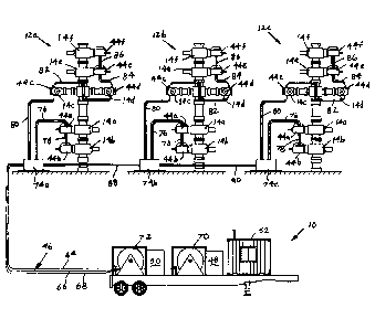
Referring to Figure 1, a first embodiment of the valve control and lubrication
system of the present disclosure is shown in the context of a representative
well
fracturing operation comprising a control trailer 10 and a number of frac
trees 12,
each of which is installed over a corresponding well bore. Each frac tree 12
comprises a plurality of flow control valves 14. As shown in Figure 2, which
is a
.. partial cross sectional view of a conventional gate valve commonly used in
frac
service, each valve 14 includes a valve body 16 through which a flowbore 18
extends, a cavity 20 which intersects the flowbore, a pair of spaced apart
seats 22
which each comprise a through bore that is aligned with the flowbore, a gate
24
which is movably positioned between the seats, and a valve stem 26 having a
first
end which is connected to the gate and a second end which is connected to a
hydraulic valve actuator 28.
The valve actuator 28 includes a piston 30 which is slidably positioned in a
cylinder 32. The piston 30 is connected to a shaft 34 which in turn is
connected to
the valve stem 26 to thereby link the piston to the gate 24. The shaft 34
extends
through a bonnet 36 which is bolted to the valve body 16 and serves to seal
the
7
Date Recue/Date Received 2020-04-28
cavity 20 from the cylinder 32. The piston 30 divides the cylinder 32 into
first and
second sealed piston chambers 38a, 38b each of which is selectively
connectable via
a corresponding conventional hydraulic fitting 40a, 40b to a hydraulic
pressure
source or a hydraulic return tank (not shown). Thus, by selectively connecting
one of
the piston chambers 38a, 38b to the hydraulic pressure source and the other
piston
chamber to the return tank, the piston 30 can be made to move the gate 24 into
a
position to either open or close the flowbore 18.
The piston chambers 38a, 38b of each valve actuator 28 are normally
connected to the hydraulic pressure source or the return tank via two separate
hydraulic hoses. A first end of each hose is connected to a corresponding
hydraulic
fitting 40a, 40b, and a second end of each hose is connected to a centralized
hydraulic power unit (HPU) which contains the hydraulic pressure source, the
return
tank and a valving device for selectively connecting each hose to either the
hydraulic
pressure source or the return tank, depending on whether the valve 14 is to be
opened or closed.
As discussed above, due to the relatively high pressures employed in fracking
operations, a possibility exists that the fracking fluid will enter the cavity
20 and
interfere with the ability of the gate 24 to form an effective seal with the
seats 22.
Accordingly, the cavity 20 is usually filled with a lubricant, such as grease.
The
lubricant not only forms a barrier to prevent the ingress of fracking fluid
into the cavity
20, but also cleans and coats the gate 24 and seat 22 sealing surfaces.
However,
over time the lubricant tends to break down and become depleted, which greatly
diminishes the ability of the lubricant to prevent the ingress of fracking
fluid into the
cavity 20 and to lubricate the gate 24 and seat 22 sealing surfaces. Also, the
act of
pumping in the grease flushes fracking fluid and debris from the valve cavity.
Therefore, additional lubricant must periodically be injected into the cavity
20 during
fracking operations.
Consequently, the gate valve 14 is normally provided with one or more
lubricant inlets 42, such as, e.g., conventional lubricant fittings, through
which the
lubricant can be injected into an interior portion of the valve, such as the
cavity 20.
8
Date Recue/Date Received 2020-04-28
As shown in Figure 2, the fittings 42 may be located, e.g., on the valve body
16 and
the bonnet 36. The lubricant can be injected manually by an operator using a
grease
pump. However, this is a time consuming process and exposes the operator to
the
dangers inherent in the areas surrounding the frac trees. As an alternative to
manually lubricating the valves, the valves may be connected to a centralized
lubrication system. In such a system, individual lubricant hoses are used to
connect
each lubricant fitting to the lubrication system, which typically comprises a
lubricant
source, a lubricant pump and a valving device for selectively connecting each
lubricant hose to the lubricant source.
Thus, prior art fracking installations which use frac trees having valves of
the
type shown in Figure 2 typically require at least three hoses to connect each
valve to
the HPU and the lubrication system: at least two hydraulic hoses to connect
the
valve to the HPU, and at least one lubricant hose to connect the valve to the
lubrication system (depending on the number of lubricant fittings 42 the valve
has).
Depending on the number of frac trees which are deployed at the frac site and
the
number of hydraulically operated valves each frac tree employs, several dozen
hoses
may be required to connect all of the valves with the HPU and the lubrication
system.
However, such a large number of hoses can be time consuming to install and
pose
trip hazards to personnel at the frac site.
The need for so many individual hoses in prior art fracking installations
arises
from the fact that the direction control valving device required to
selectively connect
each hydraulic hose to the hydraulic pressure source/return tank in the HPU
and the
valving device required to selectively connect each lubricant hose to the
lubricant
source in the lubrication system are typically located within or near the HPU
and the
lubrication system, respectively. Thus, direct connections must exist between
each
hydraulic valve actuator 28 and the direction control valving device for the
HPU, and
direct connections must exist between each lubricant port and the valving
device for
the lubrication system. In the prior art, these direct connections are
provided by the
individual hydraulic and lubricant hoses.
9
Date Recue/Date Received 2020-04-28
In accordance with the present disclosure, the need for a large number of
individual hoses to connect the HPU and the lubrication system to all of the
valves of
the fracking installation is eliminated by relocating the direction control
valving
functionality of the HPU and the lubrication system to the individual valves.
As
shown in Figure 1, this is accomplished through the use of a plurality of
control units
44, each of which is associated with a respective valve 14 and is configured
to
selectively connect the HPU and the lubrication system to the valve. As shown
in
Figure 3, each control unit 44 may be mounted to the valve actuator 28 using
conventional means, such as bolts, straps or brackets (not shown).
Alternatively,
each control unit 44 may be mounted to the valve body 16 or to a portion of
the tree
12 located proximate the valve 14. In yet another alternative, all of the
control units
44 for the valves of a particular tree 12 may be positioned on a skid or other
supporting surface (not shown) located adjacent the tree.
Referring still to Figure 1, all of the control units 44 are connectable,
either
directly or indirectly, to both a lubricant source and a hydraulic pressure
source using
a single hose set 46. In an accordance with an exemplary embodiment of the
disclosure, the lubricant source and the hydraulic pressure source may be
provided
by a lubrication system 48 and an HPU 50, respectively. The lubrication system
48
and the HPU 50 may be positioned, e.g., on the control trailer 10, which may
also
include a control center 52 for use in monitoring and controlling the fracking
operation. Referring also to Figure 4, which is a schematic diagram of the
control
trailer 10 and the control units 44 of a first tree 12a, the lubricant source
48 may
include a supply of lubricant 54 and an optional lubricant pump 56, and the
HPU may
include a tank 58 containing a supply of hydraulic fluid, a hydraulic fluid
pump 60,
and an optional accumulator 62.
In accordance with an embodiment of the present disclosure which is
particularly applicable to valves 14 of the type shown in Figure 2 in which
the valve
actuator 28 comprises two pressure chambers 38a, 38b, the first hose set 46
includes three hoses for connecting the control units 44 to the lubricant
source and
the hydraulic pressure source: a lubricant hose 64 which is connected to the
Date Recue/Date Received 2020-04-28
lubrication supply 54, a hydraulic pressure hose 66 which is connected to the
outlet
of the hydraulic fluid pump 60 or the accumulator 62, if present, and a
hydraulic
return hose 68 which is connected to the tank 58. As shown in Figure 1, the
lubricant
hose 64 may be wound on a lubricant hose reel 70, and the hydraulic pressure
and
.. return hoses 66, 68 may be wound together on a single hydraulic hose reel
72.
In the embodiment of the disclosure shown in Figure 1, the first hose set 46
is
connected to a first manifold unit 74a which is located on or adjacent a first
frac tree
12a. The first manifold unit 74a is connected via a second hose set 76 to a
first
control unit 44a which is mounted on a first valve 14a located in the lower
part of the
tree 12a. The first control unit 44a is in turn connected, via a third hose
set 78, to a
second control unit 44h which is mounted on a second valve 14b located on the
lower half of the tree. In this embodiment, the first manifold unit 74a is
also
connected, via a fourth hose set 80, to a third control unit 44c which is
mounted on a
third valve 14c located on an upper part of the tree. The third control unit
44c is in
turn connected, via a fifth hose set 82, to a fourth control unit 44d which is
mounted
on a fourth valve 14d located on the upper part of the tree. The fourth
control unit
44d is connected via a sixth hose set 84 to a fifth control unit 44e which is
mounted
on a fifth valve 14e located on the upper part of the tree. Finally, the fifth
control unit
44e is connected via a seventh hose set 86 to a sixth control unit 44f which
is
mounted on a sixth valve 14f located on the upper part of the tree.
In this embodiment, the first manifold unit 74a is also connected, via an
eighth
hose set 88, to a second manifold unit 74b located on or adjacent the second
frac
tree 12b. In a manner similar to that just described, the second manifold unit
74b is
connected, either directly or indirectly via respective hose sets 76-86, to a
number of
control units 44a-44f mounted on corresponding valves 14a-14f on the second
frac
tree 12b. Likewise, the second manifold unit 74b is connected, via another
hose set
90, to a third manifold unit 74c which is located on or adjacent a third frac
tree 12c,
and the third manifold unit 74c is connected, either directly or indirectly
via respective
hose sets 76-86, to a number of control units 44a-44f mounted on corresponding
valves 14a-14f on the third frac tree 12c. As should be apparent, this
arrangement
11
Date Recue/Date Received 2020-04-28
can be used to connect any number of frac trees to the lubrication system 48
and the
HPU 50.
Thus, instead of using individual hoses to connect each valve on each frac
tree to the lubricant and hydraulic pressure sources 48, 50, as in the prior
art, all of
the valves 14 (or more specifically all of the control units 44) are
connected, either
directly or indirectly, to the lubricant and hydraulic pressure sources using
a single
hose set. In the embodiment of the disclosure shown in Figure 1, the hose set
46 is
used to connect the lubrication system 48 and the HPU 50 to the first manifold
unit
74a at the first frac tree 12a, and then additional hose sets 76-86 are used
to connect
the first manifold unit to the various control units 44a-44f on the first frac
tree, as well
as to the second manifold unit 74b at the second frac tree 12b, and so on. In
this
manner, only relatively short hose sets are needed to connect each control 44
unit to
its corresponding manifold unit 74 and to connect each manifold unit to a
successive
manifold unit. All of the hose sets are similar to the first hose set 46 in
that they each
comprise a lubricant hose, a hydraulic pressure hose and a hydraulic return
hose. In
addition, the connections of the individual hoses within the hose sets to the
manifold
units 74 and the control units 44 may comprise any suitable, preferably
disconnectable, couplings.
In the embodiment shown in Figure 1, each manifold unit 74a, 74h, 74c is
.. connected in parallel to two control units 44a, 44c on a corresponding tree
12a, 12b,
12c, and these control units are connected in series with the remaining
control units
on that tree. However, in an alternative embodiment each manifold unit 74a,
74b,
74c may be connected in parallel to all of the control units 44 on a
corresponding tree
12a, 12b, 12c; that is, each manifold unit may be directly connected to all of
the
control units on the tree using respective hose sets. In another embodiment,
each
manifold unit 74a, 74h, 74c may be connected in series to all of the control
units on a
corresponding tree 12a, 12b, 12c; that is, each manifold unit may be connected
to a
first control unit on the tree using a first hose set, the first control unit
may be
connected to a second control unit on the tree using a second hose set, the
second
.. control unit may be connected to a third control unit on the tree using a
third hose
12
Date Recue/Date Received 2020-04-28
set, and so on. In another embodiment of the present disclosure, which will be
described below in connection with Figure 7, the control units 44 are
connected to
the lubricant source 48 and the hydraulic pressure source 50 without the use
of a
manifold unit.
Referring to Figure 4, each manifold unit 74 comprises a lubricant
distribution
manifold 92 having a lubricant line 94 and a hydraulic distribution manifold
96 having
both a hydraulic pressure line 98 and a hydraulic return line 100. The
lubricant line
94 is connected to the lubricant hose 64 of the first hose set 46 to thereby
connect
the lubricant distribution manifold 92 to the lubrication system 48. In a
similar
fashion, the hydraulic pressure and return lines 98, 100 are respectively
connected to
the hydraulic pressure and return hoses 66, 68 of the first hose set 46 to
thereby
connect the hydraulic distribution manifold 96 to the HPU 50. Each manifold
unit 74
may also include an optional accumulator 102 which is connected to the
hydraulic
pressure line 98 and serves to store a quantity of pressurized hydraulic fluid
for use
in maintaining hydraulic pressure in hose 66 as fluid is used to move a valve
actuator.
In the particular embodiment of the disclosure shown in Figure 1, the control
units 44 of each tree 12 are connected either directly or indirectly to the
lubrication
system 48 and the HPU 50 through their corresponding manifold units 74. As
shown
in Figure 4, for instance, the lubricant, hydraulic pressure and hydraulic
return lines
94, 98, 100 of the first manifold unit 74a are respectively connected to the
lubricant,
hydraulic pressure and hydraulic return hoses 64, 66, 68 of the first hose set
46 to
thereby connect the first manifold unit to the lubrication system 48 and the
HPU 50.
In addition, the first and third control units 44a, 44c are connected to the
first manifold
unit 74a through the second and fourth hose sets 76, 80 to thereby connect
these
control units to the lubrication system 48 and the HPU 50. Finally, in
accordance with
an embodiment of the disclosure which will be described below, the remaining
control
units 44h, 44d, 44e, 44f are respectively connected through the hose sets 78,
82, 84,
86 and the intervening control units to the first manifold unit 74a to thereby
connect
these control units to the lubrication system 48 and the HPU 50.
13
Date Recue/Date Received 2020-04-28
Referring also to Figure 5, each control unit 44 comprises a lubricant line
104,
a hydraulic pressure line 106 and a hydraulic return line 108. The lubricant
line 104
is connected to a lubricant inlet 110 which in turn is connectable to the
lubricant hose
of a corresponding hose set (the hose set 76 for the first control unit 44a,
for
instance). The hydraulic pressure and return lines 106, 108 are respectively
connected to a hydraulic pressure inlet 112 and a hydraulic return inlet 114,
which in
turn are respectively connectable to the hydraulic pressure and return hoses
of the
hose set. Referring also to Figure 3, each control unit 44 further comprises
at least
one lubricant port 116 which is connectable via a lubricant conduit or hose
118 to a
corresponding lubricant fitting 42 on the valve 14, and first and second
hydraulic
ports 120, 122 which are each connectable via respective first and second
hydraulic
conduits or hoses 124, 126 to a corresponding hydraulic fitting 40a, 40b on
the valve
actuator 28.
In accordance with the present disclosure, each control unit 44 additionally
includes a lubricant activation means for selectively connecting the lubricant
line 104
to the lubricant port 116 and/or a hydraulic activation means for selectively
connecting the hydraulic pressure and return lines 106, 108 to the first and
second
hydraulic ports 120, 122. In one embodiment, lubricant activation means may
include, for example, a valve 128 which is connected between the lubricant
line 104
and the lubricant port 116. The valve 128 may be a manually operated valve or,
as
shown in Figure 5, an electrically operated valve, such as a solenoid operated
directional control valve. Alternatively, the valve may be pneumatically or
hydraulically operated.
If the control unit 44 comprises a single lubricant port 116, the valve 128
may
comprise a two-way, two-position valve. If, on the other hand, the control
unit 44
comprises two lubricant ports 116, the valve 128 may comprise a three-way,
three-
position valve, such as shown in Figure 5, which is operable to selectively
connect
the lubricant line 104 to either lubricant port. Alternatively, the valve 128
may
comprise a plurality of valves of the type just described, each of which is
connected
between the lubricant line 104 and a respective lubricant port 116. Variations
of such
14
Date Recue/Date Received 2020-04-28
valves may be used to connect the lubricant line 104 to any number of
lubricant ports
42.
In an alternative embodiment, the lubricant activation means may include a
lubricant pump 130 which is positioned between the lubricant line 104 and the
lubricant port 116. In the example shown in Figure 5, the lubricant pump 130
may
comprise a conventional hydraulic intensifier pump which includes, e.g., a low
pressure cylinder 130a which is separated from a high pressure cylinder 130b
by a
movable piston 130c. The low pressure cylinder 130a is connectable to the
hydraulic
pressure and return lines 106, 108 by a valve 132, such as a spring-return
solenoid
operated cartridge valve (although other suitable valves or valve arrangements
could
be used instead), and the high pressure cylinder 130b is connected to the
lubricant
line 104.
In operation, the valve 132 is actuated to alternately connect the low
pressure
cylinder 130a to the hydraulic pressure and return lines 106, 108. When the
low
pressure cylinder 130a is connected to the hydraulic pressure line 106, the
pressure
will move the piston 130c to the right (as viewed in Figure 5), which action
will expel
the lubricant from the high pressure cylinder 130b and through the lubricant
port 116.
When the low pressure cylinder 130a is connected to the hydraulic return line
108,
the pressure in the low pressure cylinder is relieved and a return biasing
means, such
as a spring, will move the piston 130c to the left (as viewed in Figure 5),
which action
will draw the lubricant from the lubricant line 104 into the high pressure
cylinder 130b.
Thus, by alternately connecting the low pressure cylinder 130a to the
hydraulic
pressure and return lines 106, 108, the lubricant pump 130 will produce a
controlled
flow of lubricant from the lubricant line 104 through the lubricant port 116.
As shown
in Figure 5, check valves may be provided on the inlet and outlet of the high
pressure
cylinder 130b to ensure proper flow of the lubricant.
Thus, the lubricant line 104 may be selectively connected to the lubricant
port
116 by activating the valve 132 to operate the lubricant pump 130 and thereby
communicate the lubricant to the lubricant port. In embodiments in which the
control
unit 44 comprises two or more lubricant ports 116, the lubricant activation
means
Date Recue/Date Received 2020-04-28
may comprise a plurality of lubricant pumps 130, each of which is connected
between
the lubricant line and a corresponding lubricant port and is operated by a
respective
valve 132. In embodiments in which the lubricant activation means includes a
lubricant pump 130, the lubricant pump 56 in the lubrication system 48 may not
be
.. required.
In yet another alternative embodiment, the lubricant activation means may
include both the valve 128 and the lubricant pump 130. In this embodiment, the
valve 128 may be connected to the lubricant port 116, and the lubricant pump
130
may be connected between the lubricant line 104 and the valve 128. This
embodiment is particularly useful where the control unit 44 comprises two or
more
lubricant ports 116, as the valve 128 can be activated to select a particular
lubricant
port 116 to which the output of the lubricant pump 130 is connected.
In another alternative embodiment, the lubricant activation means may
comprise a conventional grease injector (not shown) which is connected between
the
lubricant line 104 and the lubricant port 116. In embodiments in which the
control
unit 44 comprises two or more lubricant ports 116, the lubricant activation
means
may comprise a plurality of grease injectors, each of which is connected
between the
lubricant line and a corresponding lubricant port. Alternatively, the
lubricant
activation means may comprise a single grease injector and a valve, such as
the
valve 128, for selectively directing the output of the grease injector to one
of the
lubricant ports.
In yet another alternative embodiment, the lubricant activation means may
comprise a conventional grease valve (not shown) which is connected between
the
lubricant line 104 and the lubricant port 116. In embodiments in which the
control
unit 44 comprises two or more lubricant ports 116, the lubricant activation
means
may comprise a plurality of grease valves, each of which is connected between
the
lubricant line and a corresponding lubricant port.
In operation, the lubricant activation means is selectively activated to
communicate lubricant from the lubricant line 104 through the lubricant port
116 and
into the lubricant hose 118. From the lubricant hose 118, the lubricant is
16
Date Recue/Date Received 2020-04-28
communicated through the lubricant fitting and into the interior portion of
the valve
14. If the valve comprises two or more lubricant ports 116, the lubricant
activation
means is activated to select which port the lubricant will be communicated
through.
In certain embodiments of the disclosure, the control unit 44 may include
means for measuring the volume of lubricant which is injected into each
lubricant
fitting 44. For example, the control unit 44 may include a sensor 130d (Figure
5) for
detecting the movement of the piston 130c within the lubricant pump 130, and
the
controller 142 may be configured to count the number of strokes of the piston
130c.
Since the volume of the high pressure cylinder 130b of the lubricant pump 130
is
.. known, the controller 142 may be configured to determine the total volume
of
lubricant discharged from the lubricant pump 130 by multiplying the volume of
the
high pressure cylinder by the number of strokes of the piston 130c. In another
alternative, in the event the lubricant activation means does not include the
lubricant
pump 130, the controller 142 may be configured to count the number of strokes
of
the lubricant pump 56 in the lubrication system 48 and sum up the total volume
of
lubricant which passes through the lubricant line 64.
Referring still to Figure 5, the hydraulic activation means may comprise, for
example, a valve 134 which is connected between the hydraulic pressure and
return
lines 106, 108 on the one hand and the hydraulic ports 120, 122 on the other
hand.
The valve 134 may be a manually operated valve or, as shown in Figure 5, an
electrically operated valve, such as a solenoid operated directional control
valve.
Alternatively, the valve can be pneumatically or hydraulically operated.
In the exemplary embodiment of the disclosure shown in Figure 5, the valve
134 comprises a four-way, three position valve. In a first position of the
valve 134,
.. the hydraulic pressure line 106 is connected to the first hydraulic port
120 and the
hydraulic return line 108 is connected to the second hydraulic port 122. In a
second
position of the valve 134, the hydraulic pressure line 106 is connected to the
second
hydraulic port 122 and the hydraulic return line 108 is connected to the first
hydraulic
port 120. In this manner, the hydraulic pressure and return lines 106, 108 can
be
selectively connected to the piston chambers 38a, 38b to either open or close
the
17
Date Recue/Date Received 2020-04-28
valve 14. In an alternative embodiment, the valve 134 may comprise an assembly
of
individual valves which together operate to selectively connect the hydraulic
pressure
and return lines 106, 108 to the first and second hydraulic ports 120, 122 in
the
manner just described.
In accordance with a further embodiment of the disclosure, each control unit
44 may also configured to connect one or more additional control units 44
and/or one
or more manifold units 74 to the lubrication system 48 and the HPU 50. As
shown in
Figure 5, each control unit 44 comprises a lubricant outlet 136 which is
connected to
the lubricant line 104, a hydraulic pressure outlet 138 which is connected to
the
hydraulic pressure line 106 and a hydraulic return outlet 140 which is
connected to
the hydraulic return line 108. Referring also to Figures 3 and 4, the
lubricant outlet
136 is connectable to the lubricant hose of a corresponding hose set (e.g.,
the hose
set 78 connecting the first control unit 44a with the second control unit
44b), and the
hydraulic pressure and return outlets 138, 140 are respectively connectable to
the
hydraulic pressure and return hoses of the hose set.
Thus, the lubricant, hydraulic pressure and hydraulic return lines 104, 106,
108
provide conduits through the control unit 44 by which the lubricant, hydraulic
pressure
and hydraulic return hoses of one hose set can be connected to the lubricant,
hydraulic pressure and hydraulic return hoses of a second hose set. In this
manner,
additional control units and/or manifold units 74 can be connected in series
with a
first control unit, and from the first control unit the additional control
units and/or
manifold units can be connected to the lubrication system 48 and the HPU 50.
In addition, the control unit 44 may be provided with one or more additional
sets of lubricant, hydraulic pressure and hydraulic return outlets 136, 138,
140 (not
shown) which are respectively connected to the lubricant, hydraulic pressure
and
hydraulic return lines 104, 106, 108. These lubricant, hydraulic pressure and
hydraulic return outlets 136, 138, 140 allow for additional corresponding hose
sets to
be connected to the lubricant, hydraulic pressure and hydraulic return lines
104, 106,
108 of the control unit 44. As a result, further control units 44 and/or
manifold units
74 can be connected in parallel with a first control unit, and from the first
control unit
18
Date Recue/Date Received 2020-04-28
these control units and/or manifold units cab be connected to the lubrication
system
48 and the HPU. It should be noted that in certain embodiments, although the
control units 44 may be connected in series, the direction control valves 134
for all
the control units 44 may be connected in parallel.
In accordance with the present disclosure, each control unit 44 includes
means for controlling its various functions and for communicating with the
frac control
center 52. As shown in Figure 5, for example, each control unit 44 may
comprise a
controller 142 which forms part of an electronics module 144 that is housed
within the
control unit. The controller 142 may be configured to operate the lubricant
activation
means to initiate the supply of lubricant to the valve 14. The controller 142
may also
be configured to operate the hydraulic activation means to open and close the
valve
14.
In certain embodiments, some or all of the functions of the controller 142 may
be controlled by a control computer 146 which is located in the frac control
center 52.
.. As shown in Figure 4, the control computer 146 may be operated by an
operator
through a conventional I/O computer 148. The control computer 146 may
alternatively or in addition be operated by an operator using, e.g., a
portable tablet-
type computing device 150 which communicates with the control computer via a
wireless router 152 or any other suitable wireless communications means.
In an exemplary embodiment of the disclosure, the controller 142 may also be
configured to communicate wirelessly with the control computer 146. For
example,
each control unit 44 may include an antenna 154 and an associated
communications
circuit which is connected to the controller 142 and is designed to
communicate
wirelessly with, e.g., the wireless router 152 or any other suitable wireless
communications means. This arrangement eliminates the need to run
communications cables from the control computer 146 to each control unit 44.
In
other embodiments, one or more communications cables can be run to each
control
unit 44 individually or bundled with the hydraulic/lubrication lines.
In accordance with another aspect of the disclosure, the electronic devices
.. within each control unit 44, including the electronics module 144 and
preferably also
19
Date Recue/Date Received 2020-04-28
the solenoid drivers for the valves 128, 132, 134 (in the event these devices
are
electrically actuated), are Class 1, Division 1-compliant. Further, the
electronic
devices may be powered by a suitable battery 156 located within the control
unit 44.
As a result, the need to run power cables to each control unit 44 is
eliminated. In
other embodiments, the control unit 44 could be powered by a power cable,
which
may be bundled with the hydraulic and lubricant lines.
Each control unit 44 may include means for monitoring certain conditions of
its
corresponding valve 14. For example, each control unit 44 may comprise one or
more position sensors 158, such as conventional Hall-effect sensors, for
detecting
.. the position of, e.g., the shaft 34 of the actuator 28 in order to provide
an indication of
whether the valve 14 is open or closed. Referring also to Figures 3 and 6, the
position sensors 158 may be mounted on a bracket 160 which is attached to a
housing 162 for the control unit 44 and connected to the electronics module
144
using corresponding leads 164. In the embodiment of the disclosure shown in
the
drawings, the control unit 44 comprises two position sensors 158: a first
position
sensor which is positioned on the bracket 160 so as to detect the shaft 34
when the
valve is in the closed position, and a second position sensor which is
positioned on
the bracket so as to detect the shaft when the valve is in the open position.
In other
embodiments a linear displacement sensor, such as a linear potentiometer, may
be
.. used to allow the exact position of the actuator shaft 34 to be detected.
In an exemplary embodiment of the disclosure, each control 44 unit may
include means for enabling an operator to manually operate certain features of
the
control unit. As shown in Figures 5 and 6, for example, each control unit 44
may
include a lubrication switch 166 to enable an operator to manually activate
the
lubricant activation means. In the case where the control unit 44 comprises
two
lubricant ports 116, the lubrication switch 166 may be configured to allow the
operator to select which port to connect the lubricant line 104 to. The
lubrication
switch 166 may also comprise a neutral, or "N", position to which the switch
is set to
enable automatic operation of the lubricant activation means. Moreover, the
switch
166 may be spring biased into this position.
Date Recue/Date Received 2020-04-28
Each control unit 44 may also include a "valve manual" switch 168 to enable
manual operation of the valve 14. When switched to the "open" position, the
controller 142 will activate the hydraulic activation means to thereby open
the valve
14. When switched to the "closed" position, the controller 142 will activate
the
hydraulic activation means to close the valve 14. The valve manual switch 168
may
also include a neutral, or "N", position to which the switch is set to enable
automatic
operation of the hydraulic activation means. As with the lubrication switch
166, the
switch 168 may be spring biased into the neutral position.
Each control unit 44 may further comprise a mode switch 170 to enable the
operator to control certain states of the control unit. For example, in the
"on" position
communication between the control unit 44 and the control computer 146 in the
frac
control center 52 is enabled. In the "off" position the control unit 44 is
placed in a low
power state. In this state, communication between the control unit 44 and the
control
computer 146, and preferably also the lubricant activation means and the
hydraulic
activation means, are disabled. Finally, in the "test" position the controller
142
enables manual operation of the lubrication and valve switches 166, 168, and,
as will
be made clear below, reads the location and function tags on the valve 14 and
tests
the indicator lamps on the control unit 44.
In the event the housing 162 for the control units 44 is required to be Class
1,
Division 1-compliant, each switch 166, 168, 170 must also be Class, Division 1
compliant. Also, the handles of switches 166, 168 and 170 may be configured
such
that in addition to being able to be activated by hand, they can be active at
some
height above the ground by means of a pole or special tool, such that the
operator is
not required to be close to the control unit 44.
In accordance with a further embodiment of the invention, each control unit 44
may include a number of visual indicators, such as status lamps, which are
operated
by the controller 142 to provide visual indications of certain conditions of
the system.
In the embodiment of the disclosure shown in Figure 5, for example, each
control unit
44 includes four different color lamps: a red lamp 172, a yellow lamp 174, a
green
lamp 176 and a blue lamp 178. The red lamp 172 may be used to indicate that
the
21
Date Recue/Date Received 2020-04-28
control unit 44 is not communicating with the control computer 146. For
example, the
controller 142 may be configured to cause the red lamp 172 to blink quickly
when a
fault condition such as a hardware or software problem exists, and to blink
slowly
when the control unit 44 is in the test mode.
The yellow lamp 174 may be used to indicate that the valve 14 is moving. For
example, the controller 142 may be configured to cause the yellow lamp 174 to
blink
quickly for two seconds prior to movement of the valve 14 and then to remain
steadily
illuminated during movement of the valve. The yellow lamp 174 may also be used
during setup of the system to identify the particular control unit 44 to which
the control
computer 146 is linked.
The green lamp 176 may be used to indicate that the control unit 44 is online,
is linked to the control computer 146 and is ready for operation. For example,
the
controller 142 may be configured to cause the green lamp 176 to blink quickly
when
the control unit 44 is communicating with the control computer 146 and to
remain
steadily illuminated when all the voltages and checks on the control unit are
good.
As with the yellow lamp 174, the green lamp 176 may also be used during setup
of
the system to identify the particular control unit 44 to which the control
computer 146
is linked.
Finally, the blue lamp 178 may be used to indicate that the lubricant
activation
means is operating. For example, the controller 142 may be configured to cause
the
blue lamp 178 to blink quickly for two seconds prior to operation of the
lubricant
activation means and to remain steadily illuminated during operation of the
lubricant
activation means.
In order to control the various aspects of the fracking operation, the control
computer 146 must know which valves 14 the control units 44 are connected to.
In
one embodiment, each control unit 44 is assigned a unique identifier, and this
identifier, along with the location and function of the valve 14 to which the
control unit
is or will be connected, is stored in digital form in a storage device which
is
accessible to the control computer 146. The location of a valve 14 can be,
e.g., the
particular tree 12 on which the valve is situated. For instance, each tree 12
can be
22
Date Recue/Date Received 2020-04-28
assigned a unique number (e.g., 1, 2, etc.), and this number can be used to
identify
the location of the valve 14. The function of the valve 14 is the specific
purpose
which the valve is intended to fulfill on the tree (e.g., upper master valve,
lower
master valve, swab valve, wing valve, etc.). Thus, the location and function
information is sufficient to identify each valve 14 at the frac site.
Consequently, the
control computer 146 can command any particular valve to be lubricated and/or
opened or closed by sending corresponding instructions to the control unit 44
whose
identification number is associated with that valve.
In another embodiment, the valve control and lubrication system of the present
.. disclosure may be configured to automatically identify the valves 14 to
which the
control units 44 are connected. As in the previous embodiment, each control
unit 44
is assigned an individual identifier. In addition, each control unit 44 is
provided with
means for designating the location and function information of the valve 14 to
which
the control unit is or will be connected, and means for determining the
location and
function information from the designating means.
The means for designating the location and function information of the valve
to
which the control unit 44 is connected may comprise a number of tags which are
encoded with the location and function information. As shown in Figure 6, for
example, the designating means may comprise two tags, a location tag 180 which
is
encoded with a distinct number that is used to identify a particular frac tree
12, and a
function tag 182 which is encoded with a discrete code to identify a
particular valve
function. This information may also be printed on the tags 180, 182 to enable
an
operator to readily discern the location and function of a specific valve 14.
The tags 180, 182 may be machine readable tags which are electrically
encoded with the location and function information. For example, the tags 180,
182
may comprise radio frequency identification (RFID) tags or any other suitable
machine readable tags. In addition, the tags 180, 182 may be either
permanently or
removably connected to the control units 44. In one embodiment, for instance,
the
tags 180, 182 are made of a magnetic material to enable them to be attached to
the
23
Date Recue/Date Received 2020-04-28
control units 44 magnetically. The tags 180, 182 can thus be removed and
replaced
with different location and function tags, if desired.
The ability to replace the tags 180, 182 provides a degree of flexibility to
the
fracking operation. For example, a particular valve 14 may be assigned a
different
function by simply removing its existing function tag 182 from the control
unit 44 and
replacing it with a tag which is encoded with a different function. From that
point on,
the control computer will associate the control unit 44 with a valve 14 having
the
function which is encoded in the new tag 182. In this manner, the fracking
operation
can be quickly and easily reconfigured by assigning different functions to
certain
valves.
The means for determining the location and function information from the tags
180, 182 may comprise a suitable electronic media reader which is connected to
the
controller 142. As shown in Figure 5, for example, if the tags 180, 182 are
RFID
tags, the means for determining the location and function information from the
tags
may comprise an RFID reader 184. In addition, the controller 142 may be
configured
such that, upon power up or being placed in the test mode, for example, the
controller will command the RFID reader 184 to read the tags 180, 182 to
determine
the location and function of the valve to which the control unit 44 is
connected. Then,
either automatically or in response to a request from the control computer
146, the
controller 142 will transmit the location and function information, along with
the
identification number of the control unit 44, to the control computer. Based
on this
information, the control computer 142 can build a data map (e.g., a table or
database) of each control unit 44 at the frac site, as well as the location
and function
of its corresponding valve 14.
Another embodiment of the valve control and/or lubrication system of the
present disclosure is shown in Figure 7. The embodiment shown in Figure 7 is
similar in many respects to the embodiment of the valve control and/or
lubrication
system shown in Figure 1. In the embodiment of Figure 7, however, the manifold
units 74 are omitted. Instead, the first hose set 46 is connected directly to
a first
control unit 44a on the first tree 12a, and the remaining control units 44b-
44f on the
24
Date Recue/Date Received 2020-04-28
first tree are connected in series with the first control unit 44a. In
addition, the last
control unit 44f on the first tree 12a is connected via a hose set 186 to the
first control
unit 14a on the second tree 12b, and the last control unit 14f on the second
tree 12b
is connected via a hose set 188 to the first control unit 14f on the third
tree 12c. In
this manner, all of the control units 44 on all of the trees 12 are connected
in series
with the lubrication system 48 and the HPU 50.
In other embodiments the manifold units 74 may be omitted and the lubricant
hose 64 and the hydraulic pressure and return hoses 66, 68 may instead be
connected to respective "T" fittings positioned on or adjacent the first tree
12a or in a
first control unit 44a on the first tree. From these "T" fittings, the first
control unit 44a
can be connected in series with the remaining control units on the first tree
12a as
well as to the lubricant hose and hydraulic pressure and return hoses leading
to the
second tree 12b, and so on.
It should be understood that the valve control and/or lubrication system of
the
present disclosure can be adapted for use with other types of valves and valve
actuators than those depicted in Figure 2. For example, in another type of
prior art
valve actuator, not shown in the drawings, the cylinder comprises a single
piston
chamber which is connectable to the hydraulic pressure source, and the
actuator
includes a spring which is connected to the shaft. By selectively connecting
the
piston chamber to the hydraulic pressure source, the piston will move the gate
in one
direction (e.g., from the closed position to the open position), and by
disconnecting
the piston chamber from the hydraulic pressure source, the spring will move
the gate
in the opposite direction (e.g., from the open position to the closed
position).
It should also be understood that the system of the present disclosure can be
adapted for use with electrical valve actuators. In such an application, the
system
would not require hydraulic pressure and return hoses and the control units
would not
require hydraulic pressure and return lines. Instead, each control unit would
be
configured to communicate electrical power to its associated valve actuator.
The
electrical power may be provided by a central power unit and communicated to,
e.g.,
Date Recue/Date Received 2020-04-28
a first control unit over a suitable power cable. From the first control unit,
the
electrical power may then be distributed to the remaining control units at the
frac site.
In these types of valves, neither the control units 44 nor the manifold units
74,
if present, require a hydraulic return line. In addition, the control units 74
require only
one hydraulic port 122, 124 and one hydraulic conduit or hose 124, 126 to
connect
the hydraulic pressure line 106 to the hydraulic actuator on the valve.
Furthermore,
the hydraulic activation means need only operate to selectively connect or
disconnect
the hydraulic pressure line 106 to the single hydraulic port 122, 124 in order
to
operate the valve. Finally, the hose sets connecting the control units 44 and
manifold
units 74 to each other and to the lubrication system 48 and the HPU 50 do not
require a hydraulic return hose.
It should be recognized that, while the present disclosure has been presented
with reference to certain embodiments, those skilled in the art may develop a
wide
variation of structural and operational details without departing from the
principles of
the disclosure. For example, the various elements shown in the different
embodiments may be combined in a manner not illustrated above. Therefore, the
following claims are to be construed to cover all equivalents falling within
the true
scope and spirit of the disclosure.
26
Date Recue/Date Received 2020-04-28