Sélection de la langue

Search

Sommaire du brevet 3079990 

Énoncé de désistement de responsabilité concernant l'information provenant de tiers

Une partie des informations de ce site Web a été fournie par des sources externes. Le gouvernement du Canada n'assume aucune responsabilité concernant la précision, l'actualité ou la fiabilité des informations fournies par les sources externes. Les utilisateurs qui désirent employer cette information devraient consulter directement la source des informations. Le contenu fourni par les sources externes n'est pas assujetti aux exigences sur les langues officielles, la protection des renseignements personnels et l'accessibilité.

Disponibilité de l'Abrégé et des Revendications

L'apparition de différences dans le texte et l'image des Revendications et de l'Abrégé dépend du moment auquel le document est publié. Les textes des Revendications et de l'Abrégé sont affichés :

  • lorsque la demande peut être examinée par le public;
  • lorsque le brevet est émis (délivrance).
(12) Brevet: (11) CA 3079990
(54) Titre français: DECLENCHEUR ELECTROMAGNETIQUE DE TYPE A CLAPET POUR DISJONCTEUR MINIATURE
(54) Titre anglais: CLAPPER-TYPE ELECTROMAGNETIC RELEASE FOR MINIATURE CIRCUIT BREAKER
Statut: Accordé et délivré
Données bibliographiques
(51) Classification internationale des brevets (CIB):
  • H01H 71/24 (2006.01)
(72) Inventeurs :
  • PAN, WANJUN (Chine)
  • YANG, YANQUN (Chine)
(73) Titulaires :
  • SHANGHAI LIANGXIN ELECTRICAL CO., LTD
(71) Demandeurs :
  • SHANGHAI LIANGXIN ELECTRICAL CO., LTD (Chine)
(74) Agent: PERRY + CURRIER
(74) Co-agent:
(45) Délivré: 2023-08-22
(86) Date de dépôt PCT: 2018-10-17
(87) Mise à la disponibilité du public: 2019-05-02
Requête d'examen: 2020-04-23
Licence disponible: S.O.
Cédé au domaine public: S.O.
(25) Langue des documents déposés: Anglais

Traité de coopération en matière de brevets (PCT): Oui
(86) Numéro de la demande PCT: PCT/CN2018/110716
(87) Numéro de publication internationale PCT: CN2018110716
(85) Entrée nationale: 2020-04-23

(30) Données de priorité de la demande:
Numéro de la demande Pays / territoire Date
201711014353.7 (Chine) 2017-10-26

Abrégés

Abrégé français

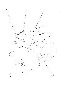
L'invention concerne un déclencheur électromagnétique de type à clapet pour disjoncteur miniature qui est caractérisé en ce qu'il comprend une armature (1), une culasse d'aimant (2), une bobine (3), un noyau de fer (4), un arbre (5), et un ressort de torsion d'armature (6). Le noyau de fer (4) est monté sur la culasse d'aimant (2). La bobine (3) est emmanchée sur le noyau de fer (4). L'armature (1) est monté sur l'arbre (5) et peut tourner autour de l'arbre (5). Le ressort de torsion d'armature (6) est monté sur l'arbre (5). Le ressort de torsion d'armature (6) s'appuie contre l'armature (1), de telle sorte que l'armature (1) peut être réinitialisée. Dans la libération électromagnétique de type à clapet pour un disjoncteur miniature dans la présente invention, au moyen de la rotation de l'armature, l'armature n'est pas fermée en absorption et le mécanisme disjoncteur n'est pas déclenché dans une plage de courant spécifiée; et lorsque la plage de courant spécifiée est dépassée, l'armature est fermée en absorption et l'armature claque un verrou, de telle sorte que le mécanisme de disjoncteur est déclenché, ce qui permet d'améliorer les performances de sécurité du disjoncteur.


Abrégé anglais

A clapper-type electromagnetic release for a miniature circuit breaker is characterized by comprising an armature (1), a magnet yoke (2), a coil (3), an iron core (4), a shaft (5), and an armature torsion spring (6). The iron core (4) is mounted on the magnet yoke (2). The coil (3) is sleeved on the iron core (4). The armature (1) is mounted on the shaft (5) and can rotate around the shaft (5). The armature torsion spring (6) is mounted on the shaft (5). The armature torsion spring (6) presses against the armature (1), so that the armature (1) can be reset. In the clapper-type electromagnetic release for a miniature circuit breaker in the present invention, by means of the rotation of the armature, the armature is not closed in absorption and the circuit breaker mechanism is not tripped within a specified current range; and when the specified current range is exceeded, the armature is closed in absorption and the armature claps a lock, so that the circuit breaker mechanism is tripped, thereby improving the safety performance of the circuit breaker.

Revendications

Note : Les revendications sont présentées dans la langue officielle dans laquelle elles ont été soumises.


What is claimed is:
1. A clapper-type electromagnetic release for a miniature circuit breaker,
comprising an armature (1), a magnet yoke (2), a coil (3), an iron core (4), a
shaft (5) and an armature torsion spring (6), wherein the iron core (4) is
mounted on the magnet yoke (2), the coil (3) is sleeved on the iron core (4),
the armature (1) is mounted on the shaft (5) and is rotatable around the shaft
(5), the armature torsion spring (6) is mounted on the shaft (5), and the
armature torsion spring (6) presses against the armature (1), so as to make
the armature reset,
wherein an inner side surface of the armature (1) extends out of rnounting
plates (101, 101), shaft installation holes (101a, 101a') are respectively
provided in the mounting plates (101, 101), two ends of the shaft (5) are
respectively rnounted in the shaft installation holes (101 a, 101a'), the
armature
torsion spring (6) is mounted on the shaft (5) and located between the
mounting plates (101, 101), and the armature torsion spring (6) has one end
lapped on a housing (7) of the circuit breaker, and the other end lapped on a
lower surface of the armature (1).
2. The clapper-type electromagnetic release for a miniature circuit breaker
according to claim 1 , wherein the magnet yoke (2) comprises a pair of magnet
yoke plates (201, 201') which are disposed face to face, fixation plates
(201a,
201a') protrude from inner side surfaces of the respective magnet yoke plates
(201, 201'), the fixation plates (201a, 201a') are respectively provided
therein
with fixing holes (201a01, 201a01'), and the fixing holes (201a01, 201a01)
are mounted on a fixing post (701) on the housing (7) to fix the magnet yoke
(2).
3. The clapper-type electromagnetic release for a miniature circuit breaker
according to claim 2, wherein two ends of the iron core (4) are respectively
mounted in installation holes (201b, 201 b') in the magnet yoke plates (201,
8
Date Recue/Date Received 2022-06-20

201), the two ends of the iron core (4) are steps (401), and step surfaces of
the steps (401) abut against the respective magnet yoke plates (201, 201').
4. The clapper-type electromagnetic release for a miniature circuit breaker
according to claim 2, wherein the armature (1) is a flat plate, upper surfaces
of the magnet yoke plates (201, 201') are flat surfaces corresponding to the
flat plate, and a front end of the armature (1) is provided with a tripping
boss
(102).
5. The clapper-type electromagnetic release for a miniature circuit breaker
according to claim 1, wherein the shaft (5) is fixedly mounted on the housing
(7) of the circuit breaker.
6. The clapper-type electromagnetic release for a miniature circuit breaker
according to claim 2, wherein the iron core (4) is in a rectangular shape, two
ends of the iron core (4) are mounted in corresponding rectangular holes
(201c, 201c') in the magnet yoke plates (201, 201'), and the two ends of the
iron core (4) pass through the rectangular holes (201c, 201c') and then are
fixedly mounted on a housing (7) of the circuit breaker.
7. The clapper-type electromagnetic release for a miniature circuit breaker
according to claim 2, wherein the iron core (4) forms an integral U-shaped
structure with the magnet yoke plates (201, 201), and the coil (3) is mounted
on a bottom plate of the U-shaped structure.
8. The clapper-type electromagnetic release for a miniature circuit breaker
according to claim 2, wherein the iron core (4) and one of the magnet yoke
plates (201, 201') together form an integral L-shaped magnet yoke iron core,
the armature (1) and the other one of the magnet yoke plates (201, 201') are
together formed in an integral L shape, and the coil (3) is mounted on a
bottom
plate of the L-shaped magnet yoke iron core.
9
Date Recue/Date Received 2022-06-20

Description

Note : Les descriptions sont présentées dans la langue officielle dans laquelle elles ont été soumises.


Clapper-type Electromagnetic Release for Miniature Circuit Breaker
Technical Field
The present disclosure pertains to the technical field of internal structures
of
circuit breakers, in particular to a clapper-type electromagnetic release for
a
miniature circuit breaker.
Background Art
Circuit breakers are classified into high-voltage circuit breakers and low-
voltage
circuit breakers according to their use ranges. The low-voltage circuit
breaker, also
called as automatic switch ("air switch" as commonly called also refers to a
low-
voltage circuit breaker), is an electric appliance which not only has the
function of
a manual switch, but also can automatically provide protections against no-
voltage,
undervoltage, overload, and short-circuit. It can be used for distributing
electric
energy, starting an asynchronous motor infrequently, protecting power supply
circuits and motors, etc. in real time, and when serious faults such as
overload,
short-circuit or undervoltage occur, it can automatically cut off the circuits
or
motors, with the function of the circuit breaker being equivalent to
combination of
a fuse type switch and an overvoltage relay, undervoltage relay or thermal
relay,
etc., and after the fault current is cut off, there is generally no need to
change parts,
so that it has been widely used.
A short-circuit protection mechanism, also called an electromagnetic release,
is
usually provided inside the circuit breaker, and when a current passing
through the
circuit breaker increases to a certain value, the electromagnetic release
causes
the circuit breaker to be rapidly tripped, so as to achieve the function of
circuit
protection. In the prior art, a linear-motion electromagnetic release is
usually
adopted, when short circuit occurs in a circuit, movable and static iron cores
are
pulled in instantaneously, the movable iron core pushes a mandril (ram) to
move
1
Date Recue/Date Received 2022-06-20

forwards, and the mandril pushes a lock to release, so that the system is
tripped.
However, such conventional electromagnetic release needs to occupy a
relatively
large volume of space, and drives the mandril to move using the movement of
the
movable iron core, therefore, the occurrence of locking of motion transmission
is
easily caused due to existence of fit clearance, so that the working stability
of the
electromagnetic release is influenced.
Summary
An object of the present disclosure is to provide a clapper-type
electromagnetic
release for a miniature circuit breaker, directed to the technical defect that
locking
of movement transmission easily occurs in the prior direct-acting
electromagnetic
release in which a mandril is drive to move by movement of a movable iron
core.
By means of rotation of an armature, it is realized that the armature is not
pulled in
and the circuit breaker mechanism is not tripped within a specified current
range,
and when the specified current range is exceeded, the armature is pulled in
and
the armature flaps a lock, so that the circuit breaker mechanism is tripped,
thereby
improving the safety performance of the circuit breaker.
Technical Solution
In order to achieve the above technical object, the clapper-type
electromagnetic
release for a miniature circuit breaker designed in the present disclosure is
featured in including an armature, a magnet yoke, a coil, an iron core, a
shaft and
an armature torsion spring, wherein the iron core is mounted on the magnet
yoke,
the coil is sleeved on the iron core, the armature is mounted on the shaft and
is
rotatable around the shaft, the armature torsion spring is mounted on the
shaft,
and the armature torsion spring presses against the armature, so that the
armature
can be reset.
Further, the magnet yoke includes a pair of magnet yoke plates which are
disposed face to face, fixation plates respectively protrude from inner side
surfaces
2
Date Recue/Date Received 2022-06-20

of the magnet yoke plates, the fixation plates are provided therein with
fixing holes,
and the fixing holes are provided on a fixing post on a housing to fix the
magnet
yoke.
Further, two ends of the iron core are respectively mounted in installation
holes
in the magnet yoke plates, wherein the two ends of the iron core are steps,
and
step surfaces of the steps abut against the respective magnet yoke plates.
Further, an inner side surface of the armature extends out of the mounting
plates, shaft installation holes are respective provided in the mounting
plates,
wherein two ends of the shaft are respectively mounted in the shaft
installation
holes, the armature torsion spring is mounted on the shaft and located between
the mounting plates, and the armature torsion spring has one end lapped on the
housing, and the other end lapped on a lower surface of the armature.
Further, the armature is a flat plate, wherein upper surfaces of the magnet
yoke
plates are flat surfaces corresponding to the flat plate, and a front end of
the
armature is provided with a tripping boss.
Further, the shaft is fixedly mounted on a housing.
Further, the iron core is in a rectangular shape, wherein two ends of the iron
core are mounted in corresponding rectangular holes in the magnet yoke plates,
and the two ends of the iron core pass through the rectangular holes and then
are
fixedly mounted on the housing.
Further, the iron core forms an integral U-shaped structure with the magnet
yoke
plates, and the coil is mounted on a bottom plate of the U-shaped structure.
Further, the iron core forms an integral L-shaped magnet yoke iron core with
one of the magnet yoke plates, the armature forms an integral L shape with the
other one of the magnet yoke plates, and the coil is mounted on a bottom plate
of
the L-shaped magnet yoke iron core.
3
Date Recue/Date Received 2022-06-20

Beneficial Effects
In the clapper-type electromagnetic release for a miniature circuit breaker
provided in the present disclosure, by using rotation of the armature, it is
realized
that the armature is not pulled in and the circuit breaker mechanism is not
tripped
within a specified current range, and when the specified current range is
exceeded,
the armature is pulled in and the armature flaps a lock, so that the circuit
breaker
mechanism is tripped, thereby improving the safety performance of the circuit
breaker.
Brief Description of Drawings
FIG. 1 is a structural schematic view of Embodiment 1 of the present
disclosure;
FIG. 2 is an exploded view of Embodiment 1 of the present disclosure;
FIG. 3 is a diagram showing a state in which Embodiment 1 of the present
disclosure is not clapped;
FIG. 4 is a diagram showing a state in which Embodiment 1 of the present
disclosure is clapped;
FIG. 5 is a diagram showing a state in which Embodiment 1 of the present
disclosure is not clapped in a circuit breaker;
FIG. 6 is a diagram showing a state in which Embodiment 1 of the present
disclosure is clapped in the circuit breaker;
FIG. 7 is a structural schematic view of Embodiment 2 of the present
disclosure;
FIG. 8 is a schematic front view of Embodiment 2 of the present disclosure;
FIG. 9 is a structural schematic view of Embodiment 3 of the present
disclosure;
and
4
Date Recue/Date Received 2022-06-20

FIG. 10 is a structural schematic view of Embodiment 4 of the present
disclosure.
Detailed Description of Embodiments
The present disclosure is further described below in connection with
accompanying drawings and embodiments.
Embodiment 1
As shown in FIG. 1 and FIG. 2, a clapper-type electromagnetic release for a
miniature circuit breaker includes an armature 1, a magnet yoke 2, a coil 3,
an iron
core 4, a shaft 5 and an armature torsion spring 6, wherein the iron core 4 is
mounted on the magnet yoke 2, the coil 3 is sleeved on the iron core 4, the
armature 1 is mounted on the shaft 5 and is rotatable around the shaft 5, the
armature torsion spring 6 is mounted on the shaft 5, and the armature torsion
spring 6 presses against the armature 1, so that the armature can be reset.
Specifically, in the present embodiment, the magnet yoke 2 includes a pair of
magnet yoke plates 201, 201' which are disposed face to face, fixation plates
201a,
201a' respectively protrude from inner side surfaces of the magnet yoke plates
201, 201', the fixation plates 201a, 201a' are respectively provided therein
with
fixing holes 201a01, 201a01', and the fixing holes 201a01, 201a01' are
provided
on a fixing post 701 on a housing 7 to fix the magnet yoke 2. Two ends of the
iron
core 4 are respectively mounted in installation holes 201b, 201b' in the
magnet
yoke plates 201, 201', the two ends of the iron core 4 are steps 401, wherein
step
surfaces of the steps 401 abut against the respective magnet yoke plates 201,
201'. An inner side surface of the armature 1 extends out of the mounting
plates
101, 101', shaft installation holes 101a, 101a' are respectively provided in
the
mounting plates 101, 101', wherein two ends of the shaft 5 are respectively
mounted in the shaft installation holes 101a, 101a', and two ends of the shaft
5
pass through the shaft installation holes 101a, 101a' and then are fixedly
mounted
Date Recue/Date Received 2022-06-20

on the housing 7. The armature torsion spring 6 is mounted on the shaft 5 and
located between the mounting plates 101, 101', and the armature torsion spring
6
has one end lapped on the housing 7, and the other end lapped on a lower
surface
of the armature 1.
The armature 1 is a flat plate, wherein upper surfaces of the magnet yoke
plates
201, 201' are flat surfaces corresponding to the flat plate, and a front end
of the
armature 1 is provided with a tripping boss 102.
As shown in FIG. 3 and FIG.5, when a relatively small current passes through
the coil 3 of the electromagnetic release, an attraction force between the
armature
1 and the magnet yoke 2 of the electromagnetic release is smaller than a
counter
force from the armature torsion spring 6, then the armature 1 is kept in a
static
state under the action of the armature torsion spring 6, and the armature 1
does
not flap the lock, so that the circuit breaker is not tripped;
As shown in FIG. 4 and FIG. 6, when the circuit breaker is closed, and when
the
current passing through the coil 3 is greater than a certain value, the
attraction
force between the armature 1 and the magnet yoke 2 of the electromagnetic
release is greater than the counter force from the armature torsion spring 6,
then
the armature 1 overcomes the counter force from the armature torsion spring 6
under the action of the attraction force to rotate around the shaft 5 towards
the
direction of the magnet yoke 2, and flaps the lock so that the circuit breaker
is
tripped.
After the circuit breaker is open, the armature 1 will restore to an unclapped
state
under the action of the armature torsion spring 6.
Embodiment 2
As shown in FIG. 7 and FIG. 8, the iron core 4 is in a rectangular shape,
wherein
two ends of the iron core 4 are mounted in corresponding rectangular holes
201c,
201c' in the magnet yoke plates 201, 201', and the two ends of the iron core 4
pass
6
Date Recue/Date Received 2022-06-20

through the rectangular holes 201c, 201c' and then are fixedly mounted on the
housing 7. A working process of the present embodiment is the same as
Embodiment 1 and will not be further illustrated herein.
Embodiment 3
As shown in FIG. 9, the iron core 4 can also form an integral U-shaped
structure
with the magnet yoke plates 201, 201', and the coil 3 is mounted on a bottom
plate
of the U-shaped structure.
Embodiment 4
As shown in FIG. 10, the iron core 4 can also form an integral L-shaped magnet
yoke iron core with one of the magnet yoke plates 201, 201', the armature 1
forms
an integral L shape with the other one of the magnet yoke plates 201, 201',
and
the coil 3 is mounted on a bottom plate of the L-shaped magnet yoke iron core.
The structures, ratios, sizes, quantities and so on depicted in the
accompanying
drawings of the present embodiment are only used to match the contents
disclosed
in the description, to be understood and read by those familiar with the art,
rather
than being used for limiting conditions under which the present disclosure can
be
implemented, therefore, they do not have technical significance, and any
structural
modifications, changes of ratio relations, or adjustments of sizes, without
affecting
the efficacy and the purpose that can be produced and achieved by the present
disclosure, shall still fall within the scope that can be covered by the
technical
contents disclosed in the present disclosure. Meanwhile, wordings such as
"upper", "lower", "left", "right", "middle", "clockwise", and
"counterclockwise"
referred to in the present description are also used for clarity of
description only,
rather than being used to limit the implementable scope of the present
disclosure,
and changes or adjustment of the relative relationship therebetween, without
substantial technical changes, also should be considered as the implementable
scope of the present disclosure.
7
Date Recue/Date Received 2022-06-20

Dessin représentatif
Une figure unique qui représente un dessin illustrant l'invention.
États administratifs

2024-08-01 : Dans le cadre de la transition vers les Brevets de nouvelle génération (BNG), la base de données sur les brevets canadiens (BDBC) contient désormais un Historique d'événement plus détaillé, qui reproduit le Journal des événements de notre nouvelle solution interne.

Veuillez noter que les événements débutant par « Inactive : » se réfèrent à des événements qui ne sont plus utilisés dans notre nouvelle solution interne.

Pour une meilleure compréhension de l'état de la demande ou brevet qui figure sur cette page, la rubrique Mise en garde , et les descriptions de Brevet , Historique d'événement , Taxes périodiques et Historique des paiements devraient être consultées.

Historique d'événement

Description Date
Lettre envoyée 2023-08-22
Inactive : Octroit téléchargé 2023-08-22
Accordé par délivrance 2023-08-22
Inactive : Page couverture publiée 2023-08-21
Préoctroi 2023-06-13
Inactive : Taxe finale reçue 2023-06-13
Lettre envoyée 2023-04-18
Un avis d'acceptation est envoyé 2023-04-18
Inactive : Approuvée aux fins d'acceptation (AFA) 2023-03-15
Inactive : Q2 réussi 2023-03-15
Modification reçue - réponse à une demande de l'examinateur 2022-06-20
Modification reçue - modification volontaire 2022-06-20
Rapport d'examen 2022-03-04
Inactive : Rapport - Aucun CQ 2022-03-04
Inactive : Supprimer l'abandon 2022-01-07
Inactive : Lettre officielle 2022-01-07
Inactive : Soumission d'antériorité 2022-01-07
Inactive : Demande ad hoc documentée 2022-01-07
Inactive : Correspondance - Poursuite 2021-12-06
Réputée abandonnée - omission de répondre à une demande de l'examinateur 2021-10-08
Modification reçue - réponse à une demande de l'examinateur 2021-09-29
Modification reçue - modification volontaire 2021-09-29
Rapport d'examen 2021-06-08
Inactive : Rapport - Aucun CQ 2021-06-01
Inactive : Correspondance - PCT 2021-04-01
Représentant commun nommé 2020-11-07
Inactive : Page couverture publiée 2020-06-11
Lettre envoyée 2020-06-04
Inactive : CIB en 1re position 2020-05-26
Lettre envoyée 2020-05-26
Exigences applicables à la revendication de priorité - jugée conforme 2020-05-26
Demande de priorité reçue 2020-05-26
Inactive : CIB attribuée 2020-05-26
Demande reçue - PCT 2020-05-26
Exigences pour l'entrée dans la phase nationale - jugée conforme 2020-04-23
Exigences pour une requête d'examen - jugée conforme 2020-04-23
Toutes les exigences pour l'examen - jugée conforme 2020-04-23
Demande publiée (accessible au public) 2019-05-02

Historique d'abandonnement

Date d'abandonnement Raison Date de rétablissement
2021-10-08

Taxes périodiques

Le dernier paiement a été reçu le 2022-09-19

Avis : Si le paiement en totalité n'a pas été reçu au plus tard à la date indiquée, une taxe supplémentaire peut être imposée, soit une des taxes suivantes :

  • taxe de rétablissement ;
  • taxe pour paiement en souffrance ; ou
  • taxe additionnelle pour le renversement d'une péremption réputée.

Les taxes sur les brevets sont ajustées au 1er janvier de chaque année. Les montants ci-dessus sont les montants actuels s'ils sont reçus au plus tard le 31 décembre de l'année en cours.
Veuillez vous référer à la page web des taxes sur les brevets de l'OPIC pour voir tous les montants actuels des taxes.

Historique des taxes

Type de taxes Anniversaire Échéance Date payée
Taxe nationale de base - générale 2020-04-23 2020-04-23
Requête d'examen - générale 2023-10-17 2020-04-23
TM (demande, 2e anniv.) - générale 02 2020-10-19 2020-08-26
TM (demande, 3e anniv.) - générale 03 2021-10-18 2021-08-31
TM (demande, 4e anniv.) - générale 04 2022-10-17 2022-09-19
Taxe finale - générale 2023-06-13
TM (brevet, 5e anniv.) - générale 2023-10-17 2023-09-15
Titulaires au dossier

Les titulaires actuels et antérieures au dossier sont affichés en ordre alphabétique.

Titulaires actuels au dossier
SHANGHAI LIANGXIN ELECTRICAL CO., LTD
Titulaires antérieures au dossier
WANJUN PAN
YANQUN YANG
Les propriétaires antérieurs qui ne figurent pas dans la liste des « Propriétaires au dossier » apparaîtront dans d'autres documents au dossier.
Documents

Pour visionner les fichiers sélectionnés, entrer le code reCAPTCHA :


Pour visualiser une image, cliquer sur un lien dans la colonne description du document. Pour télécharger l'image (les images), cliquer l'une ou plusieurs cases à cocher dans la première colonne et ensuite cliquer sur le bouton "Télécharger sélection en format PDF (archive Zip)" ou le bouton "Télécharger sélection (en un fichier PDF fusionné)".

Liste des documents de brevet publiés et non publiés sur la BDBC .

Si vous avez des difficultés à accéder au contenu, veuillez communiquer avec le Centre de services à la clientèle au 1-866-997-1936, ou envoyer un courriel au Centre de service à la clientèle de l'OPIC.


Description du
Document 
Date
(aaaa-mm-jj) 
Nombre de pages   Taille de l'image (Ko) 
Dessin représentatif 2023-08-03 1 10
Description 2020-04-22 7 300
Dessins 2020-04-22 5 111
Revendications 2020-04-22 2 88
Dessin représentatif 2020-04-22 1 13
Abrégé 2020-04-22 1 25
Revendications 2021-09-28 2 87
Dessins 2021-09-28 5 143
Description 2022-06-19 7 455
Revendications 2022-06-19 2 132
Courtoisie - Lettre confirmant l'entrée en phase nationale en vertu du PCT 2020-06-03 1 588
Courtoisie - Réception de la requête d'examen 2020-05-25 1 433
Avis du commissaire - Demande jugée acceptable 2023-04-17 1 579
Taxe finale 2023-06-12 3 114
Certificat électronique d'octroi 2023-08-21 1 2 527
Traité de coopération en matière de brevets (PCT) 2020-04-22 12 482
Rapport de recherche internationale 2020-04-22 4 140
Traité de coopération en matière de brevets (PCT) 2020-04-22 2 77
Déclaration 2020-04-22 4 77
Demande d'entrée en phase nationale 2020-04-22 5 140
Modification - Abrégé 2020-04-22 2 93
Correspondance reliée au PCT 2021-01-01 3 145
Correspondance reliée au PCT 2021-03-31 3 132
Correspondance reliée aux formalités 2021-05-31 3 104
Demande de l'examinateur 2021-06-07 3 175
Correspondance de la poursuite 2021-12-05 25 1 197
Modification / réponse à un rapport 2021-09-28 22 924
Modification / réponse à un rapport 2021-09-28 3 128
Courtoisie - Lettre du bureau 2022-01-06 1 178
Demande de l'examinateur 2022-03-03 3 165
Modification / réponse à un rapport 2022-06-19 12 545
Correspondance reliée au PCT 2022-12-19 3 147
Correspondance reliée au PCT 2023-01-18 3 148
Correspondance reliée au PCT 2023-02-17 3 147
Correspondance reliée au PCT 2023-03-16 3 147
Correspondance reliée au PCT 2023-04-15 3 150