Note : Les descriptions sont présentées dans la langue officielle dans laquelle elles ont été soumises.
CA 03081830 2020-05-05
TERMINAL APPARATUS, BASE STATION APPARATUS, AND COMMUNICATION
METHOD
Technical Field
[00011
The present invention relates to a terminal apparatus, a base station
apparatus, and
a communication method.
This application claims priority based on JP 2017-219904 filed on November 15,
2017, the contents of which are incorporated herein by reference.
Background Art
[00021
In the 3rd Generation Partnership Project (3GPP), a radio access method and a
radio network for cellular mobile communications (hereinafter referred to as
"Long Term
Evolution (LTE)"or "Evolved Universal Terrestrial Radio Access (EUTRA)") have
been
studied. In LTE, a base station apparatus is also referred to as an evolved
NodeB
(eNodeB), and a terminal apparatus is also referred to as user equipment (UE).
LTE is a
cellular communication system in which multiple areas are deployed in a
cellular
structure, with each of the multiple areas being covered by a base station
apparatus. A
single base station apparatus may manage multiple serving cells.
[00031
The 3GPP has been studying a next generation standard (New Radio or NR) (NPL
1) to make a proposal for International Mobile Telecommunication (IMT)-2020, a
standard for a next-generation mobile communication system, standardized by
the
International Telecommunication Union (ITU). NR is required to satisfy
requirements for
three scenarios including enhanced Mobile BroadBand (eMBB), massive Machine
Type
Communication (mMTC), and Ultra Reliable and Low Latency Communication (URLLC)
in a single technology framework.
Citation List
Non Patent Literature
[00041
NPL 1: "New SID proposal: Study on New Radio Access Technology," RP-
160671, NTT docomo, 3GPP TSG RAN Meeting #71, Goteborg, Sweden, 7th to 10th
March, 2016.
Summary of Invention
Technical Problem
[00051
1
Date Recue/Date Received 2020-05-05
CA 03081830 2020-05-05
One aspect of the present invention provides a terminal apparatus efficiently
performing communication, a communication method used for the terminal
apparatus, a
base station apparatus efficiently performing communication, and a
communication
method used for the base station apparatus.
Solution to Problem
[00061
(1) A first aspect of the present invention is a terminal apparatus including
a
coding unit configured to code one transport block and UCI, and a transmitter
configured
to transmit the one transport block and the UCI on one PUSCH. The one
transport block
is mapped to at least a first resource group of a first antenna port and a
second resource
group of a second antenna port. A UL PTRS is mapped to a third resource group
of the
first antenna port, and mapped to no resource element of the second antenna
port. The
UCI is mapped to at least a fourth resource group of the first antenna port
and a fifth
resource group of the second antenna port. An index pair of resource element
included in
the fifth resource group is different from any of index pairs of resource
elements included
in the third resource group, and the index pair is a pair of a subcarrier
index and an
OFDM symbol index of a resource element.
[00071
(2) A second aspect of the present invention is a base station apparatus
including a
receiver configured to receive one PUSCH that includes one transport block and
UCI, and
is transmitted, and a decoding unit configured to decode the transport block
and the UCI.
The one transport block is mapped to at least a first resource group of a
first antenna port
and a second resource group of a second antenna port. A UL PTRS is mapped to a
third
resource group of the first antenna port, and mapped to no resource element of
the second
antenna port. The UCI is mapped to at least a fourth resource group of the
first antenna
port and a fifth resource group of the second antenna port. An index pair of
resource
element included in the fifth resource group is different from any of index
pairs of
resource elements included in the third resource group, and the index pair is
a pair of a
subcarrier index and an OFDM symbol index of a resource element.
[00081
(3) A third aspect of the present invention is a communication method used for
a
terminal apparatus, the method including coding one transport block and UCI,
and
transmitting the one transport block and the UCI on one PUSCH. The one
transport block
is mapped to at least a first resource group of a first antenna port and a
second resource
group of a second antenna port. A UL PTRS is mapped to a third resource group
of the
first antenna port, and mapped to no resource element of the second antenna
port. The
UCI is mapped to at least a fourth resource group of the first antenna port
and a fifth
resource group of the second antenna port. An index pair of resource element
included in
2
Date Recue/Date Received 2020-05-05
CA 03081830 2020-05-05
the fifth resource group is different from any of index pairs of resource
elements included
in the third resource group, and the index pair is a pair of a subcarrier
index and an
OFDM symbol index of a resource element.
[00091
(4) A fourth aspect of the present invention is a communication method
including
receiving one PUSCH that includes one transport block and UCI, and is
transmitted, and
decoding the transport block and the UCI. The one transport block is mapped to
at least a
first resource group of a first antenna port and a second resource group of a
second
antenna port. A UL PTRS is mapped to a third resource group of the first
antenna port,
and mapped to no resource element of the second antenna port. The UCI is
mapped to at
least a fourth resource group of the first antenna port and a fifth resource
group of the
second antenna port. An index pair of resource element included in the fifth
resource
group is different from any of index pairs of resource elements included in
the third
resource group, and the index pair is a pair of a subcarrier index and an OFDM
symbol
index of a resource element.
Advantageous Effects of Invention
[00101
According to one aspect of the present invention, the terminal apparatus can
communicate efficiently. The base station apparatus can communicate
efficiently.
Brief Description of Drawings
[00111
FIG. 1 is a conceptual diagram of a radio communication system according to
one
aspect of the present embodiment.
FIG. 2 is an example illustrating a relationship between Nsl'symb, subcarrier
spacing configuration , slot configuration, and CP configuration according to
one aspect
of the present embodiment.
FIG. 3 is a schematic diagram illustrating an example of a resource grid in a
subframe according to one aspect of the present embodiment.
FIG. 4 is s diagram illustrating an example of a coding of a transport block
ak
(ao, aA_I) in a baseband unit 13 according to one aspect of the present
embodiment.
FIG. 5 is a diagram illustrating an example of a first coding method of a bit
sequence cucio in a case that KUCI is 1 according to one aspect of the present
embodiment.
FIG. 6 is a diagram illustrating an example of the first coding method of a
bit
sequence cucik (cucio, cucii) in a case that KUCI is 2 according to one aspect
of the
present embodiment.
3
Date Recue/Date Received 2020-05-05
CA 03081830 2020-05-05
FIG. 7 is a diagram illustrating an example of mapping of a concatenated
sequence
gk and a rate matching sequence eucik to PUSCH resource elements according to
one
aspect of the present embodiment.
FIG. 8 is a diagram illustrating an example of, in a case that one codeword is
mapped to a first antenna port and a second antenna port, mapping of a
concatenated
sequence gk and a rate matching sequence eucik for the second antenna port to
the PUSCH
according to one aspect of the present embodiment.
FIG. 9 is a schematic block diagram illustrating a configuration of a terminal
apparatus 1 according to one aspect of the present embodiment.
FIG. 10 is a schematic block diagram illustrating a configuration of a base
station
apparatus 3 according to one aspect of the present embodiment.
Description of Embodiments
[0012]
Embodiments of the present invention will be described below.
[0013]
FIG. 1 is a conceptual diagram of a radio communication system according to
one
aspect of the present embodiment. In FIG. 1, a radio communication system
includes
terminal apparatuses lA to 1C and a base station apparatus 3. Hereinafter, the
terminal
apparatuses lA to 1C are each also referred to as a terminal apparatus 1.
[0014]
Hereinafter, a frame structure will be described.
[0015]
In a radio communication system according to one aspect of the present
embodiment, at least an Orthogonal Frequency Division Multiplex (OFDM) is
used. An
OFDM symbol which is a unit of a time domain of the OFDM includes at least one
or
multiple subcarriers, and is converted to a time-continuous signal in
generating the
baseband signal.
[0016]
A SubCarrier Spacing (SCS) may be given by a subcarrier spacing Af = 211.15
kHz.
For example, "p," has any value of 0 to 5. For a Carrier bandwidth part (CBP),
the value
used to configure the subcarrier spacing may be given by a higher layer
parameter
(subcarrier spacing configuration p,).
[0017]
In the radio communication system according to one aspect of the present
embodiment, a time unit Ts is used to represent a length of a time domain. The
time unit
Ts is given by Ts = 1/(Afm,x=Nf). Afm,,x may be the maximum value of the
subcarrier
spacing supported in the radio communication system according to one aspect of
the
4
Date Recue/Date Received 2020-05-05
CA 03081830 2020-05-05
present embodiment. Afm,,x may be Afm,,x = 480 kHz. The time unit Ts is also
referred to
as T. A constant lc is lc = Afm,x=Nf/(AfrefNfief) = 64. Afref is 15 kHz, and
Nfief = 2048.
[00181
The constant lc may be a value indicating a relationship between a reference
subcarrier spacing and T. The constant lc may be used for the length of the
subframe. The
number of slots included in the subframe may be given based on at least the
constant K.
Afref is a reference subcarrier spacing, and Nfjef is a value corresponding to
the reference
subcarrier spacing.
[00191
A transmission in the downlink and/or a transmission in the uplink includes a
frame having a length of 10 ms. The frame includes 10 subframes. A length of
the
subframe is 1 ms. A length of the frame may be given regardless of the
subcarrier spacing
Af. In other words, a frame configuration may be given not based on t. The
length of the
subframe may be given regardless of the subcarrier spacing Af. In other words,
a
subframe configuration may be given not based on t.
[00201
For the subcarrier spacing configuration t, the number and index of slots
included
in the subframe may be given. For example, a first slot number Os may be given
in
ascending order ranging from 0 to Nsubfr'gslet - 1 in the subframe. For the
subcarrier
spacing configuration t, the number and index of slots included in the frame
may be
given. For example, a second slot number n'1,,f may be given in ascending
order ranging
from 0 to Nfrdm"siet - 1 in the frame. Consecutive Nsi tsymb OFDM symbols may
be
included in one slot. The Nsi'symb may be given based on at least a part or
all of a slot
configuration and Cyclic Prefix (CP) configuration. The slot configuration may
be given
by a higher layer parameter slot_configuration. The CP configuration may be
given based
on at least the higher layer parameters. The CP configuration may be given
based on at
least dedicated RRC signaling.
[00211
FIG. 2 is an example illustrating a relationship between Wi'symb, the
subcarrier
spacing configuration t, the slot configuration, and the CP configuration
according to one
aspect of the present embodiment. In FIG. 2A, in a case that the slot
configuration is 0
and the CP configuration is a normal cyclic prefix (CP), Nsi'symb = 14,
Nfrdm"siet = 40,
and Nsubfrdme'llsiet = 4. In FIG. 2B, in a case that the slot configuration is
0 and the CP
configuration is an extended cyclic prefix (CP), Nsi'symb = 12, Nfrdm"siet =
40, and
Nsubframe,
slot ¨ 4. Nsietsymb for the slot configuration of 0 may correspond to two
times
Nslotsymb for the slot configuration of 1.
[00221
Hereinafter, a physical resource will be described.
[00231
Date Recue/Date Received 2020-05-05
CA 03081830 2020-05-05
An antenna port is defined based on that a channel on which a symbol is
communicated through one antenna port can be estimated from a channel on which
another symbol is communicated through the same antenna port. In a case that a
large
scale property of a channel on which a symbol is communicated through one
antenna port
can be estimated from a channel on which a symbol is communicated through the
other
antenna port, these two antenna ports are referred to as being Quasi Co-
Located (QCL).
The large scale property may include at least a long term performance of the
channel. The
large scale property may include some or all of delay spread, Doppler spread,
Doppler
shift, average gain, average delay, and beam parameters (spatial Rx
parameters). A first
antenna port and a second antenna port being QCL for the beam parameters may
mean
that a reception beam a receiving side assumes for the first antenna port is
the same as a
reception beam the receiving side assumes for the second antenna port. The
first antenna
port and the second antenna port being QCL for the beam parameters may mean
that a
transmission beam the receiving side assumes for the first antenna port is the
same as a
transmission beam the receiving side assumes for the second antenna port. In
the case
that the large scale property of a channel on which a symbol is communicated
through
one antenna port can be estimated from a channel on which a symbol is
communicated
through the other antenna port, the terminal apparatus 1 may assume these two
antenna
ports to be QCL. Two antenna ports being QCL may be equivalent to these two
antenna
ports being assumed to be QCL.
[00241
For each of the subcarrier spacing configurations and a set of carriers, a
resource
grid of NPRB,.NRBse subcarriers and N( )symbNsubframe,u
symb OFDM symbols is given. NPRB,x
may indicate the number of resource blocks given for the subcarrier spacing
configuration p, for a carrier x. The carrier x indicates either a downlink
carrier or an
uplink carrier. In other words, x is "DL" or "UL". NPRB is referred as
including NPRB,D).
and NPRB,UL. NRBse may indicate the number of sub carriers included in one
resource
block. One resource grid may be provided for each antenna port p and/or for
each
subcarrier spacing configuration p, and/or for each transmission direction
configuration.
The transmission direction includes at least a DownLink (DL) and an UpLink
(UL).
Hereinafter, a set of parameters including at least some or all of the antenna
port p, the
subcarrier spacing configuration t, and the transmission direction
configuration is also
referred to as a first radio parameter set. In other words, the resource grid
may be given,
one for each first radio parameter set.
[00251
A carrier corresponding to a serving cell in the downlink is referred to as a
downlink carrier (or a downlink component carrier). A carrier corresponding to
a serving
cell in the uplink is referred to as an uplink carrier (or an uplink component
carrier). The
6
Date Recue/Date Received 2020-05-05
CA 03081830 2020-05-05
downlink component carrier and the uplink component carrier are collectively
referred to
as a component carrier.
[00261
Each element in the resource grid provided for each first radio parameter set
is
referred to as a resource element. The resource element is identified by an
index kse of a
frequency domain and an index 1 of a time domain. For a first radio parameter
set, a
resource element is identified by an index kse of the frequency domain and an
index 1 of
the time domain. The resource element identified by the index kse of the
frequency
domain and the index 1 of the time domain is also referred to as a resource
element
1). The index kse of the frequency domain indicates any value from 0 to
N'IRBNRB, - 1.
I\P1RB may be the number of resource blocks given for the subcarrier spacing
configuration t.is is the number of subcarriers included in the resource
block, and
NRBse _ 12 holds. The index kse of the frequency domain may correspond to a
subcarrier
index kse. The index 1 of the time domain may correspond to an OFDM symbol
index 1.
[00271
FIG. 3 is a schematic diagram illustrating an example of a resource grid in a
subframe according to one aspect of the present embodiment. In the resource
grid of FIG.
3, a horizontal axis is the index 1 of the time domain and a vertical axis is
the index k se of
the frequency domain. In one subframe, the frequency domain of the resource
grid
includes IVRBNRBse subcarriers, and the time domain of the resource grid may
include
14.2 t OFDM symbols. The resource block includes NRBse subcarriers. The time
domain
of the resource block may correspond to one OFDM symbol. The time domain of
the
resource block may correspond to 14 OFDM symbols. The time domain of the
resource
block may correspond to one or multiple slots. The time domain of the resource
block
may correspond to one subframe.
[00281
The terminal apparatus 1 may be indicated to perform transmission and/or
reception using only a subset of resource grids. The subset of the resource
grids is also
referred to as a carrier bandwidth part, and the carrier bandwidth part may be
given by
higher layer parameters and/or the DCI. The carrier bandwidth part is also
referred to as a
bandwidth part (BP). In other words, the terminal apparatus 1 need not be
indicated to
perform transmission and/or reception using all sets of resource grids. In
other words, the
terminal apparatus 1 may be indicated to perform transmission and/or reception
using
some frequency resources in the resource grid. One carrier bandwidth part
includes
multiple resource blocks in the frequency domain. One carrier bandwidth part
may
include multiple resource blocks continuous in the frequency domain. The
carrier
bandwidth part is also referred to as a Band Width Part (BWP). The carrier
bandwidth part
configured for the downlink carrier is also referred to as a downlink carrier
bandwidth
7
Date Recue/Date Received 2020-05-05
CA 03081830 2020-05-05
part. The carrier bandwidth part configured for the uplink carrier is also
referred to as an
uplink carrier bandwidth part.
[0029]
A set of downlink carrier bandwidth parts may be configured for each serving
cell.
The set of downlink carrier bandwidth parts may include one or multiple
downlink carrier
bandwidth parts. A set of uplink carrier bandwidth parts may be configured for
each
serving cell. The set of uplink carrier bandwidth parts may include one or
multiple uplink
carrier bandwidth parts.
[0030]
The higher layer parameter is a parameter included in higher layer signaling.
The
higher layer signaling may be a Radio Resource Control (RRC) signaling or a
Medium
Access Control Control Element (MAC CE). Here, the higher layer signaling may
be the
RRC layer signaling or MAC layer signaling.
[0031]
The higher layer signaling may be common RRC signaling. The common RRC
signaling includes at least some or all of the following feature Cl to feature
C3.
Feature Cl) Being mapped to a BCCH logical channel or a CCCH logical channel
Feature C2) Including at least radioResourceConfigCommon information element.
Feature C3) Being mapped to a PBCH.
[0032]
The radioResourceConfigCommon information element may include information
indicating a configuration commonly used in the serving cell. The
configuration
commonly used in the serving cell may include at least a PRACH configuration.
The
PRACH configuration may indicate at least one or multiple random access
preamble
indexes. The PRACH configuration may indicate at least a PRACH time/frequency
resource.
[0033]
The higher layer signaling may be dedicated RRC signaling. The dedicated RRC
signaling includes at least some or all of the following features D1 or D2.
Feature DO Being mapped to a DCCH logical channel.
Feature D2) Including at least radioResourceConfigDedicated information
element.
[0034]
The radioResourceConfigDedicated information element may include at least
information indicating a configuration specific to the terminal apparatus 1.
The
radioResourceConfigDedicated information element may include at least
information
indicating a configuration of the carrier bandwidth part. The configuration of
the carrier
bandwidth part may indicate at least a frequency resource of the carrier
bandwidth part.
[0035]
8
Date Recue/Date Received 2020-05-05
CA 03081830 2020-05-05
For example, a MIB, first system information, and second system information
may
be included in the common RRC signaling. A higher layer message mapped to the
DCCH
logical channel and including at least radioResourceConfigCommon may be
included in
the common RRC signaling. A higher layer message mapped to the DCCH logical
channel and not including the radioResourceConfigCommon information element
may be
included in the dedicated RRC signaling. The higher layer message mapped to
the DCCH
logical channel and including at least the radioResourceConfigDedicated
information
element may be included in the dedicated RRC signaling.
[0036]
The first system information may indicate at least a time index of a
Synchronization Signal (SS) block. An SS block is also referred to as an
SS/PBCH block.
The first system information may include information associated with a PRACH
resource.
The first system information may include information associated with an
initial
connection configuration. The second system information may be system
information
other than the first system information.
[0037]
The radioResourceConfigDedicated information element may include at least the
information on the PRACH resource. The radioResourceConfigDedicated
information
element may include at least the information on the initial connection
configuration.
[0038]
A physical channel and a physical signal according to various aspects of the
present embodiment will be described below.
[0039]
An uplink physical channel may correspond to a set of resource elements
carrying
information generated in the higher layer. The uplink physical channel is a
physical
channel used in the uplink. In the radio communication system according to one
aspect of
the present embodiment, at least some or all of the uplink physical channels
described
below are used.
- Physical Uplink Control CHannel (PUCCH)
- Physical Uplink Shared CHannel (PUSCH)
- Physical Random Access CHannel (PRACH)
[0040]
The PUCCH may be used to transmit Uplink Control Information (UCI). The
uplink control information includes Channel State Information (CSI), a
Scheduling
Request (SR), and a Hybrid Automatic Repeat request ACKnowledgement (HARQ -
ACK)
for downlink data (Transport block (TB), Medium Access Control Protocol Data
Unit
(MAC PDU), Downlink-Shared Channel (DL-SCH), Physical Downlink Shared Channel
(PDSCH). The HARQ-ACK may indicate an acknowledgement (ACK) or negative-
acknowledgement (NACK) for the downlink data.
9
Date Recue/Date Received 2020-05-05
CA 03081830 2020-05-05
[0041]
The HARQ-ACK may indicate an ACK or NACK corresponding to each of the one
or multiple Code Block Groups (CBGs) included in the downlink data. The HARQ-
ACK
is also referred to as HARQ feedback, HARQ information, HARQ control
information,
and ACK/NACK.
[0042]
The scheduling request may be used to request the PUSCH resource for initial
transmission.
[0043]
The channel state information may include some or all of a Channel Quality
Indicator (CQI) and a Rank Indicator (RI). The channel quality indicator may
include a
Precoder Matrix Indicator (PMI). The CQI is an indicator associated with
channel quality
(for example, propagation strength), and the PMI is an indicator indicating a
precoder.
The RI is an indicator indicating a transmission rank (or the number of
transmission
layers).
[0044]
The PUSCH is used to transmit uplink data (TB, MAC PDU, UL-SCH, PUSCH).
The PUSCH may be used to transmit the HARQ-ACK and/or channel state
information
along with the uplink data. Furthermore, the PUSCH may be used to transmit
only the
channel state information or to transmit only the HARQ-ACK and the channel
state
information. The PUSCH is used to transmit a random access message 3.
[0045]
The PUSCH is given based on at least some or all of Scrambling, Modulation,
layer mapping, Transform precoding, precoding, and Mapping to physical
resource. The
terminal apparatus 1 may assume that the PUSCH is given based on at least some
or all of
scrambling, modulation, layer mapping, transform precoding, precoding, and
mapping to
physical resource.
[0046]
In the scrambling, for a codeword q, a block b(q)(i) of bits may be scrambled
based
on at least a scrambling sequence c(q)(i) to generate b(q),c(i). In the block
b(q)(i) of bits, i
is an index representing a value ranging from 0 to M(q)bit - 1. M(q)bit may
represent the
number of bits of the codeword q transmitted on the PUSCH. The scrambling
sequence
c(q)(i) may be a sequence given based on at least a pseudo-random function
(e.g., a M
sequence, a Gold sequence, or the like). In the scrambling, for the codeword
q, the block
b(q)(i) of bits may be scrambled based on the scrambling sequence c(q)(i) and
the
following Equation (1) to generate block b(q),(i) of scrambling bits.
Equation 1
Date Recue/Date Received 2020-05-05
CA 03081830 2020-05-05
b(q) ( 1) = rnod(b(f7)(1) c(4) (i),2)
[0047]
mod(A, B) may be a function that outputs a remainder of A divided by B. mod(A,
B) may be a function that outputs a value corresponding to a remainder of A
divided by
B.
[0048]
In the modulation, for the codeword q, the block b(q),c(i) of scrambling bits
may be
modulated based on a prescribed modulation scheme, and a block d(mod) of
complex-
valued modulation symbols may be generated. In the block d(mod) of complex-
valued
modulation symbols, in.' represents a value ranging from 0 to M(q)symb - 1.
M(q)symb may
represent the number of complex-valued modulation symbols of the codeword q
transmitted on the PUSCH. The prescribed modulation scheme may include at
least some
or all of Quadrature Phase Shift Keying (QPSK), 16 Quadrature Amplitude
Modulation
(QAM), 64 QAM, 256 QAM, and the like. Note that the prescribed modulation
scheme
may be given based on at least the DCI for scheduling the PUSCH.
[0049]
In the layer mapping, the block d(q)(imad) of complex-valued modulation
symbols
for each codeword is mapped to one or multiple layers based on a prescribed
mapping
procedure, and a block x(i\--1 ) f ayer./ (3_ complex-valued modulation
symbols may be generated.
In the block x(iLyer) of complex-valued modulation symbols, ilayer represents
a value
ranging from 0 to MLYersymb - 1. MLYersymb may represent the number of complex-
valued
modulation symbols per layer. The block x (i
\-layer) of the complex-valued modulation
symbols may be x(iLyer) _ [x(0)(ilayer) x )
(v-1)(ilayers,T.
] Here, NT may indicate that rows
and columns of "*" are transposed. The number of elements in the block
x(ilayer./ (3_ ) f complex-valued modulation symbols may correspond to the
number of layers for all code
words transmitted on the PUSCH. Here, v represents the number of layers for
the
PUSCH.
[0050]
In a case that the transform precoding is configured for the PUSCH, v = 1
holds,
and the block x(iLyer) of complex-valued modulation symbols is divided into
sets of
miiiyersymb/mpuscHse complex-valued modulation symbols. Here, mPUSCHse may
correspond
to the number of subcarriers allocated for the PUSCH. MPuscHse may be given by
mpuscHRB x NRBse. mpuscHRB may represent a band of the PUSCH represented as
the
number of resource blocks. MPuscHaB may represent the number of resource
blocks
included in the PUSCH. In the case that the transform precoding is configured
for the
PUSCH, it may be configured to satisfy mpuscHRB _ 2a2 x 3a3 x 5a5.
Here, a2 represents
11
Date Recue/Date Received 2020-05-05
CA 03081830 2020-05-05
an integer that is not negative. a3 represents an integer that is not
negative. a5 represents
an integer that is not negative. NRBse may represent the number of subcarriers
included in
the resource block. Specifically, NRBse may be NRBse = 12. Each of the sets of
mtiyersymb/mpuscHse complex-valued modulation symbols may correspond to one
OFDM
symbol.
[00511
In the case that the transform precoding is configured for the PUSCH, a block
y(k)(iLyer) of complex-valued modulation symbol mays be given based on at
least the
following Equation (2).
Equation 2
m rtrsok4 2/111c,
)(1 PiSelf kro _Tit piaci E x(A)(,
sc AG
iVi .1=0
SC
[00521
In Equation (2), X, represents the index of the layer. In the case that the
transform
precoding is configured for the PUSCH, X, may be X, = O. j represents an
imaginary unit. 7t
represents the ratio of the circumference of a circle to its diameter. e
represents the
Napier's constant. kse represents a range from 0 to MPuscHse - 1. 1 represents
a range from
0 to Mtiyersymb/mpuscHse _ 1.
[00531
In a case that the transform precoding is not configured for the PUSCH, the
block
y(k)(i1ayer) of the complex-valued modulation symbols may be y(k)(iLyer) =
x(k)(iLyer).
[00541
In the precoding, the block y(ilayer) of complex-valued modulation symbols may
be
subjected to a prescribed precoding to give z(idp). y(ilayer) may be y(ilayer)
= [Y( )(itayer)
y(v-1)(ilayeolT. =ap
represents a value ranging from 0 to MLYersymb - 1. Z(lap) may be Z(lap) =
[z"(idp) Z(13-1)(jap)1T. Here, in a case that a matrix for the precoding is
W, z(idP) = Wy
(ilayer) may be given. P represents the number of antenna ports for the PUSCH.
P may be
the same as v. In the precoding, the block y(ilayer) of complex-valued
modulation symbols
may be converted to the block z(idp) of complex-valued modulation symbols for
P antenna
ports. The number of rows in the matrix W for the precoding may correspond to
the
number P of antenna ports. The number of columns in the matrix W for the
precoding
may correspond to the number v of layers.
[00551
For the matrix W for the precoding, one or multiple codebooks may be
configured.
The number of codebooks may be given based on at least the number X, of layers
for the
PUSCH and/or the number P of antenna ports for the PUSCH. In codebook based
12
Date Recue/Date Received 2020-05-05
CA 03081830 2020-05-05
transmission, one codebook may be selected for the PUSCH. In non codebook
based
transmission, the matrix W for the precoding may be an identity matrix.
[00561
In the codebook based transmission, the block Y(2')(i1ayer) of complex-valued
modulation symbols mapped to one layer may correspond to a prescribed number
of
antenna ports. The prescribed number may correspond to the number of rows in
the
matrix W for the precoding. In the codebook based transmission, block
Y(2')(i1ayer) of
complex-valued modulation symbols mapped to one layer may correspond to all
antenna
ports for the PUSCH. In the non codebook based transmission, block
Y(2')(i1ayer) of
complex-valued modulation symbols mapped to one layer may correspond to one
antenna
port. In the non codebook based transmission, the block y(2")(i1ayer) of the
complex-valued
modulation symbols mapped to one layer may be y(2")(i1ayer) = Z(P)(ilayer). p
represents an
index for the antenna port.
[00571
In the case that the transform precoding is not configured for the PUSCH, in
mapping (physical resource mapping) to the physical resource, block z(P)(idp)
of complex-
valued modulation symbols for the antenna port p may be mapped to the resource
elements (kse, 1) of the resource blocks allocated for the PUSCH with priority
being given
to the subcarrier index kse, except for the resource elements at least
satisfying some or all
of elements Al to A4 below. Here, p may represent the index of the antenna
port. p
represents a value ranging from 0 to P - 1. Here, the mapping with priority
being given to
the subcarrier index kse may be mapping to the resource element (kse, 1) in
such an order,
from kse to kse + M (M represents a prescribed value) in the symbol 1, from
kse to kse + M
in the symbol 1 + 1, ..., and from kse to kse + M in the symbol 1 + N (N
represents a
prescribed value).
Element Al) Resource element to which a UL DMRS associated with the PUSCH
is mapped.
Element A2) Resource Element to which a UL PTRS is mapped.
Element A3) Resource to which an SRS transmission is configured.
Element A4) Reservation resource
[00581
The reservation resource may be a resource that is at least configured for
rate
matching of the PUSCH. The reservation resource may be indicated by a group
common
PDCCH.
[00591
The index kse of the frequency domain and the index 1 of the time domain
included
in the resource element (kse, 1) are also referred to as an index pair. The
index pair
includes at least an index kse of the frequency domain and the index 1 of the
time domain.
The index pair may not include the index p of the antenna port. The index pair
of the
13
Date Recue/Date Received 2020-05-05
CA 03081830 2020-05-05
resource element indicated by the index k, of the frequency domain and the
index 1 of
the time domain is also referred to as an index pair (k,, 1).
[00601
In the case that the transform precoding is configured for the PUSCH, in
mapping
(physical resource mapping) to the physical resource, block z(P)(ic,p) of
complex-valued
modulation symbols for the antenna port p may be mapped to the resource
elements
1) of the resource blocks allocated for the PUSCH with priority being given to
the
subcarrier index except for the resource elements at least satisfying some
or all of
elements B1 to B4 below. Here, p may represent the index of the antenna port.
p
represents a value ranging from 0 to P - 1. Here, the mapping with priority
being given to
the subcarrier index k, may be mapping to the resource element (k,, 1) in such
an order,
from kõ to kõ + M (M represents a prescribed value) in the symbol 1, from k,
to k, + M
in the symbol 1 + 1, ..., and from k, to k, + M in the symbol 1 + N (N
represents a
prescribed value).
Element B1) OFDM symbol including at least a resource element to which a UL
DMRS associated with the PUSCH is mapped.
Element B2) Resource Element to which a UL PTRS is mapped.
Element B3) Resource to which an SRS transmission is configured.
Element B4) Reservation Resource
[00611
Regardless of whether or not the transform precoding is configured for the
PUSCH, in mapping (physical resource mapping) to the physical resource, block
z(P)(idp)
of complex-valued modulation symbols for the antenna port p may be mapped to
the
resource elements (kse, 1) of the resource blocks allocated for the PUSCH with
priority
being given to the subcarrier index kse, except for the resource elements at
least satisfying
some or all of elements B1 to B4 below. Here, p may represent the index of the
antenna
port. p represents a value ranging from 0 to P - 1. Here, the mapping with
priority being
given to the subcarrier index k, may be mapping to the resource element (kse,
1) in such
an order, from k, to k, + M (M represents a prescribed value) in the symbol 1,
from kse
to k, + M in the symbol 1 + 1, ..., and from kõ to k, + M in the symbol 1 + N
(N
represents a prescribed value).
Element Cl) Resource element to which a UL DMRS associated with the PUSCH
is mapped.
Element C2) Resource Element to which a UL PTRS is mapped.
Element C3) Resource to which an SRS transmission is configured.
Element C4) Reservation Resource
[00621
The PRACH may be used to transmit a random access preamble (random access
message 1). The PRACH is used to indicate an initial connection establishment
14
Date Recue/Date Received 2020-05-05
CA 03081830 2020-05-05
procedure, a handover procedure, a connection re-establishment procedure,
synchronization (timing adjustment) for uplink data transmission, and a
request for the
PUSCH resource. The random access preamble may be used to notify the base
station
apparatus 3 of an index (random access preamble index) given by the higher
layer of the
terminal apparatus 1.
[00631
The random access preamble may be provided by cyclic-shifting of a Zadoff-Chu
sequence corresponding to a physical root sequence index u. The Zadoff-Chu
sequence
may be generated based on the physical root sequence index u. In a single
serving cell,
multiple random access preambles may be defined. The random access preamble
may be
identified based on at least the index of the random access preamble.
Different random
access preambles corresponding to different indices of random access preambles
may
correspond to different combinations of the physical root sequence index u and
the cyclic
shift. The physical root sequence index u and the cyclic shift may be provided
based on at
least information included in the system information. The physical root
sequence index u
may be an index for identifying a sequence included in the random access
preamble. The
random access preamble may be identified based on at least the physical root
sequence
index u.
[00641
In FIG. 1, the following uplink physical signal is used for the uplink radio
communication. The uplink physical signals may not be used to transmit
information
output from a higher layer, but is used by a physical layer.
- UpLink Demodulation Reference Signal (UL DMRS)
- Sounding Reference Signal (SRS)
- UpLink Phrase Tracking Reference Signal (UL PTRS)
[00651
The UL DMRS is associated with transmission of the PUSCH and/or the PUCCH.
The UL DMRS is multiplexed with the PUSCH or the PUCCH. The base station
apparatus 3 may use the UL DMRS in order to perform channel compensation of
the
PUSCH or the PUCCH. Hereinafter, transmission of both the PUSCH and the UL
DMRS
associated with the PUSCH is simply referred as transmission of the PUSCH.
Hereinafter,
transmission of both the PUCCH and the UL DMRS associated with the PUCCH is
simply referred as transmission of the PUCCH. The UL DMRS associated with the
PUSCH is also referred to as a UL DMRS for PUSCH. The UL DMRS associated with
the
PUCCH is also referred to as a UL DMRS for PUCCH.
[00661
The SRS need not be associated with transmission of the PUSCH or the PUCCH.
The base station apparatus 3 may use the SRS for measuring a channel state.
The SRS
Date Recue/Date Received 2020-05-05
CA 03081830 2020-05-05
may be transmitted at the end of the subframe in an uplink slot or in a
prescribed number
of OFDM symbols from the end.
[00671
The UL PTRS may be a reference signal that is used at least for phase
tracking.
The UL PTRS may be associated with an UL DMRS group that includes at least an
antenna port used for one or multiple UL DMRSs. The UL PTRS being associated
with
the UL DMRS group may be equivalent to some or all of the antenna ports for
the UL
PTRS and the antenna ports included in the UL DMRS groups being at least QCL.
The
UL DMRS group may be identified based on at least the lowest index antenna
port for the
UL DMRS included in the UL DMRS group. The UL PTRS may be mapped to the lowest
index antenna port of one or multiple antenna ports to which one codeword is
mapped. In
a case that one codeword is mapped to at least a first layer and a second
layer, the UL
PTRS may be mapped to the first layer. The UL PTRS may not be mapped to the
second
layer. The index of the antenna port to which the UL PTRS is mapped may be
given based
on at least the downlink control information.
[00681
In FIG. 1, the following downlink physical channels are used for downlink
radio
communication from the base station apparatus 3 to the terminal apparatus 1.
The
downlink physical channels are used by the physical layer for transmission of
information
output from the higher layer.
- Physical Broadcast Channel (PBCH)
- Physical Downlink Control Channel (PDCCH)
- Physical Downlink Shared Channel (PDSCH)
[00691
The PBCH is used to transmit a master information block (MIB, BCH, or
Broadcast Channel). The PBCH may be transmitted based on a prescribed
transmission
interval. For example, the PBCH may be transmitted at an interval of 80 ms.
Contents of
information included in the PBCH may be updated at every 80 ms. The PBCH may
include 288 subcarriers. The PBCH may include two, three, or four OFDM
symbols. The
MIB may include information on an identifier (index) of a synchronization
signal. The
MIB may include information for indicating at least some of the number of the
slot in
which PBCH is transmitted, the number of the subframe in which PBCH is
transmitted,
and the number of the radio frame in which PBCH is transmitted.
[00701
The PDCCH is used to transmit Downlink Control Information (DCI). The
downlink control information is also called a DCI format. The downlink control
information may at least include any of a downlink grant or an uplink grant.
The DCI
format used for the scheduling of the PDSCH may be referred to as a downlink
grant. The
16
Date Recue/Date Received 2020-05-05
CA 03081830 2020-05-05
DCI format used for the scheduling of the PUSCH may be referred to as an
uplink grant.
The downlink grant is also referred to as a downlink assignment or a downlink
allocation.
[00711
The DCI format may include at least some or all of a TBS information field
mapped to information bits that indicate at least a size of a transport block
(Transport
Block Size (TBS)) transmitted on the PDSCH, a resource allocation information
field
(Resource allocation field) mapped to information bits that indicate at least
a set of
resource blocks to which the PDSCH is mapped in the frequency domain, an MCS
information field mapped to information bits that indicate at least a
modulation scheme
for the PDSCH, a HARQ process number information field mapped to information
bits
that indicate at least a HARQ process number corresponding to the transport
block, an
NDI indication information field mapped to information bits that indicate at
least a New
Data Indicator (NDI) corresponding to the transport block, and an RV
information field
mapped to information bits that indicate at least a Redundancy Version (RV)
for the
transport block.
[00721
One or multiple information fields included in the DCI format may be mapped to
information bits provided by joint coding of the multiple pieces of indication
information. For example, the DCI format may include the MCS information field
mapped to information bits provided based on at least joint coding of the
information
associated with the TBS and the information indicating the modulation scheme
of the
PDSCH.
[00731
In various aspects of the present embodiment, unless otherwise specified, the
number of resource blocks indicates the number of resource blocks in the
frequency
domain.
[00741
One downlink grant is used at least for scheduling of one PDSCH within one
serving cell. The downlink grant is used at least for the scheduling of the
PDSCH in the
same slot as the slot in which the downlink grant is transmitted.
[00751
One uplink grant is used at least for scheduling of one PUSCH in one serving
cell.
[00761
One physical channel is mapped to one serving cell. One physical channel is
mapped to multiple serving cells.
[00771
The terminal apparatus 1 is configured with one or multiple Control Resource
Sets
(CORESETs) for searching for the PDCCH. The terminal apparatus 1 attempts to
receive
the PDCCH in the one or multiple control resource sets.
17
Date Recue/Date Received 2020-05-05
CA 03081830 2020-05-05
[00781
The control resource set may indicate a time frequency domain in which one or
multiple PDCCHs can be mapped. The control resource set may be a region in
which the
terminal apparatus 1 attempts to receive the PDCCH. The control resource set
may
include a continuous resource (Localized resource). The control resource set
may include
a non-continuous resource (distributed resource).
[00791
In the frequency domain, the unit of mapping the control resource sets may be
a
resource block. For example, in the frequency domain, the unit of mapping the
control
resource sets may be six resource blocks. In the time domain, the unit of
mapping the
control resource sets may be the OFDM symbol. For example, in the time domain,
the
unit of mapping the control resource sets may be one OFDM symbol.
[00801
The frequency domain of the control resource set may be identical to the
system
bandwidth of the serving cell. The frequency domain of the control resource
set may be
provided based on at least the system bandwidth of the serving cell. The
frequency
domain of the control resource set may be provided based on at least higher
layer
signaling and/or downlink control information.
[00811
The time domain of the control resource set may be provided based on at least
higher layer signaling and/or downlink control information.
[00821
A control resource set may be a Common control resource set. The common
control resource set may be a control resource set configured commonly to the
multiple
terminal apparatuses 1. The common control resource set may be provided based
on at
least some or all of the MIB, the first system information, the second system
information,
the common RRC signaling, and a cell ID. For example, a time resource and/or
frequency
resource of the control resource set configured to monitor the PDCCH used for
the
scheduling of the first system information may be given based on at least the
MIB.
[00831
A control resource set may be a dedicated control resource set. The dedicated
control resource set may be a control resource set configured to be
dedicatedly used for
the terminal apparatus 1. The dedicated control resource set may be provided
based on at
least some or all of the dedicated RRC signaling and a value of C-RNTI.
[00841
The control resource set may include a set of PDCCHs (or PDCCH candidates) to
be monitored by the terminal apparatus 1. The control resource set may include
one or
multiple Search Spaces (SS).
[00851
18
Date Recue/Date Received 2020-05-05
CA 03081830 2020-05-05
The search space includes one or multiple PDCCH candidates of an aggregation
level. The terminal apparatus 1 receives a PDCCH candidate included in the
search space
and attempts to receive the PDCCH. Here, the PDCCH candidate is also referred
to as a
blind detection candidate.
[00861
A set of search spaces includes one or multiple search spaces. A set of search
areas
may be a Common Search Space (CSS). The CSS may be provided based on at least
some
or all of the MIB, the first system information, the second system
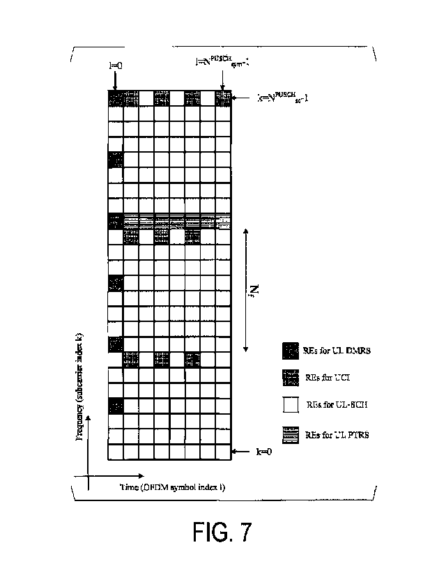
information, the
common RRC signaling, and the cell ID.
[00871
A set of search spaces may be a UE-specific Search Space (USS). The USS may be
provided based on at least some or all of the dedicated RRC signaling and the
value of C -
RNTI.
[00881
The common control resource set may include at least one or both of the CSS
and
the USS. The dedicated control resource set may include at least one or both
of the CSS
and the USS.
[00891
A physical resource of the search space includes a configuration unit of the
control
channels (a Control Channel Element (CCE)). The CCE includes a prescribed
number of
Resource Element Groups (REGs). For example, the CCE may include six REGs. The
REG may include one OFDM symbol in one Physical Resource Block (PRB). In other
words, the REG may include 12 Resource Elements (REs). The PRB is also simply
referred to as a Resource Block (RB).
[00901
The PDSCH is used to transmit downlink data (DL-SCH, PDSCH). The PDSCH is
used at least to transmit the random access message 2 (random access
response). The
PDSCH is used at least to transmit system information including parameters
used for
initial access.
[00911
In FIG. 1, the following downlink physical signals are used for the downlink
radio
communication. The downlink physical signal need not be used for transmitting
the
information output from the higher layer, but is used by the physical layer.
- Synchronization signal (SS)
- DownLink Demodulation Reference Signal (DL DMRS)
- Shared Reference Signal (Shared RS)
- Channel State Information-Reference Signal (CSI-RS)
- DownLink Phrase Tracking Reference Signal (DL PTRS)
- Tracking Reference Signal (TRS)
19
Date Recue/Date Received 2020-05-05
CA 03081830 2020-05-05
[00921
The synchronization signal is used for the terminal apparatus 1 to establish
synchronization in the frequency domain and/or time domain in the downlink.
The
synchronization signal includes a Primary Synchronization Signal (PSS) and a
Secondary
Synchronization Signal (SSS).
[00931
The SS block (SS/PBCH block) includes at least some or all of the PSS, the
SSS,
and the PBCH. The respective antenna ports for some or all of the PSS, the
SSS, and the
PBCH included in the SS block may be the same. Some or all of the PSS, the
SSS, and
the PBCH included in the SS block may be mapped to continuous OFDM symbols.
The
respective CP configurations for some or all of the PSS, the SSS, and the PBCH
included
in the SS block may be the same. The respective configurations p, of the
subcarrier
spacing for some or all of the PSS, the SSS, and the PBCH included in the SS
block may
be the same.
[00941
The DL DMRS is associated with transmission of the PBCH, the PDCCH and/or
the PDSCH. The DL DMRS is multiplexed with the PBCH, the PDCCH, or the PDSCH.
The terminal apparatuses 1 may use the DL DMRS corresponding to the PBCH, the
PDCCH, or the PDSCH in order to perform channel compensation of the PBCH, the
PDCCH, or the PDSCH. Hereinafter, the transmission of both the PBCH and the DL
DMRS associated with the PBCH is simply referred to as transmission of the
PBCH.
Hereinafter, transmission of both of the PDCCH and the DL DMRS associated with
the
PDCCH is simply referred to as transmission of the PDCCH. Hereinafter,
transmission of
both of the PDSCH and the DL DMRS associated with the PDSCH is simply referred
to
as transmission of the PDSCH. The DL DMRS associated with the PBCH is also
referred
to as a DL DMRS for PBCH. The DL DMRS associated with the PDSCH is also
referred
to as a DL DMRS for PDSCH. The DL DMRS associated with the PDCCH is also
referred to as a DL DMRS associated with the PDCCH.
[00951
The Shared RS may be associated with at least the transmission of the PDCCH.
The Shared RS may be multiplexed with the PDCCH. The terminal apparatuses 1
may use
the Shared RS in order to perform channel compensation of the PDCCH.
Hereinafter,
transmission of both the PDCCH and the Shared RS associated with the PDCCH is
also
simply referred to as transmission of the PDCCH.
[00961
The DL DMRS may be a reference signal configured individually for the terminal
apparatus 1. A sequence of the DL DMRS may be given based on at least
parameters
configured individually for the terminal apparatus 1. The sequence of the DL
DMRS may
be given based on at least a UE-specific value (e.g., a C-RNTI, and the like).
The DL
Date Recue/Date Received 2020-05-05
CA 03081830 2020-05-05
DMRS may be individually transmitted for the PDCCH and/or the PDSCH. On the
other
hand, the Shared RS may be a reference signal which is configured commonly to
multiple
terminal apparatuses 1. A sequence of the Shared RS may be given regardless of
the
parameters configured individually for the terminal apparatus 1. For example,
the
sequence of the Shared RS may be given based on at least some of the number of
the slot,
the number of a mini slot, and the cell identity (ID). The Shared RS may be a
reference
signal to be transmitted regardless of whether or not the PDCCH and/or the
PDSCH are
transmitted.
[00971
The CSI-RS may be a signal that is used at least to calculate the channel
state
information. A pattern of the CSI-RS assumed by the terminal apparatus may be
given by
at least a higher layer parameter.
[00981
The PTRS may be a signal that is used at least to compensate a phase noise. A
pattern of the PTRS assumed by the terminal apparatus may be given based on at
least a
higher layer parameter and/or the DCI.
[00991
The DL PTRS may be associated with a DL DMRS group that includes at least an
antenna port used for one or multiple DL DMRSs. The DL PTRS being associated
with
the DL DMRS group may be equivalent to that some or all of the antenna ports
for the
DL PTRS and the antenna ports included in the DL DMRS groups are at least QCL.
The
DL DMRS group may be identified based on at least the lowest index antenna
port for the
DL DMRS included in the DL DMRS group.
[01001
The TRS may be a signal that is used at least to establish synchronization in
the
time and/or the frequency. A pattern of the TRS assumed by the terminal
apparatus may
be given based on at least a higher layer parameter and/or the DCI.
[01011
The downlink physical channels and the downlink physical signals are also
collectively referred to as downlink signals. The uplink physical channels and
the uplink
physical signals are also collectively referred to as uplink signals. The
downlink signals
and the uplink signals are also collectively referred to as physical signals.
The downlink
signals and the uplink signals are also collectively referred to as signals.
The downlink
physical channels and the uplink physical channels are collectively referred
to as physical
channels. The downlink physical signals and the uplink physical signals are
collectively
referred to as physical signals.
[01021
The Broadcast CHannel (BCH), the Uplink Shared CHannel (UL-SCH) and the
Downlink-Shared CHannel (DL-SCH) are transport channels. A channel used in a
21
Date Recue/Date Received 2020-05-05
CA 03081830 2020-05-05
Medium Access Control (MAC) layer is referred to as a transport channel. A
unit of the
transport channels used in the MAC layer is also referred to as a transport
block (TB) or a
MAC PDU. A Hybrid Automatic Repeat reQuest (HARQ) is controlled for each
transport
block in the MAC layer. The transport block is a unit of data that the MAC
layer delivers
to the physical layer. In the physical layer, the transport block is mapped to
a codeword,
and a modulation process is performed for each codeword.
[01031
The base station apparatus 3 and the terminal apparatus 1 exchange (transmit
and/or receive) higher layer signaling in the higher layer. For example, the
base station
apparatus 3 and the terminal apparatus 1 may transmit and/or receive Radio
Resource
Control (RRC) signaling (also referred to as a Radio Resource Control (RRC)
message or
Radio Resource Control (RRC) information) in a Radio resource control (RRC)
layer.
Furthermore, the base station apparatus 3 and the terminal apparatus 1 may
transmit
and/or receive the MAC Control Element (CE) in the MAC layer. Here, the RRC
signaling and/or the MAC CE is also referred to as higher layer signaling.
[01041
The PUSCH and the PDSCH may be used at least to transmit the RRC signaling
and/or the MAC CE. Here, the RRC signaling transmitted from the base station
apparatus
3 on the PDSCH may be signaling common to the multiple terminal apparatuses 1
in the
serving cell. The signaling common to the multiple terminal apparatuses 1 in
the serving
cell is also referred to as common RRC signaling. The RRC signaling
transmitted from
the base station apparatus 3 on the PDSCH may be signaling dedicated to a
certain
terminal apparatus 1 (also referred to as dedicated signaling or UE specific
signaling).
The signaling dedicated to the terminal apparatus 1 is also referred to as
dedicated RRC
signaling. A higher layer parameter specific to the serving cell may be
transmitted by
using the signaling common to the multiple terminal apparatuses 1 in the
serving cell or
the signaling dedicated to the certain terminal apparatus 1. A UE-specific
higher layer
parameter may be transmitted by using the signaling dedicated to the certain
terminal
apparatus 1. The PDSCH including the dedicated RRC signaling may be scheduled
via
the PDCCH in the first control resource set.
[01051
The Broadcast Control CHannel (BCCH), the Common Control CHannel (CCCH),
and the Dedicated Control CHannel (DCCH) are logical channels. For example,
the
BCCH is a channel of the higher layer used to transmit the MIB. The Common
Control
CHannel (CCCH) is a channel of the higher layer used to transmit information
common
to the multiple terminal apparatuses 1. Here, the CCCH is used for a terminal
apparatus 1
that is not in an RRC-connected state, for example. The Dedicated Control
CHannel
(DCCH) is a channel of the higher layer used to transmit control information
dedicated to
22
Date Recue/Date Received 2020-05-05
CA 03081830 2020-05-05
the terminal apparatus 1 (dedicated control information). Here, the DCCH is
used for a
terminal apparatus 1 that is in the RRC -connected state, for example.
[0106]
The BCCH in the logical channel may be mapped to the BCH, the DL-SCH, or the
UL-SCH in the transport channel. The CCCH in the logical channel may be mapped
to
the DL-SCH or the UL-SCH in the transport channel. The DCCH in the logical
channel
may be mapped to the DL-SCH or the UL-SCH in the transport channel.
[0107]
The UL-SCH in the transport channel is mapped to the PUSCH in the physical
channel. The DL-SCH in the transport channel is mapped to the PDSCH in the
physical
channel. The BCH in the transport channel is mapped to the PBCH in the
physical
channel.
[0108]
A coding method for the codeword q of the PUSCH will be described below. Here,
the codeword q corresponds to at least one transport block ak.
[0109]
FIG. 4 is s diagram illustrating an example of a coding of a transport block
ak
(ao,
aA_i) in a baseband unit 13 according to one aspect of the present embodiment.
The
baseband unit 13 may include at least some or all of a CRC generator 3001, a
Code block
segmentation unit 3002, a Low Density Parity Check (LDPC) encoder 3003, a Bit
selection unit 3004, a Bit interleaving unit 3005, and a Code block
concatenation unit
3006.
[0110]
The CRC generator 3001 generates a first CRC sequence pk (po,
pLi_i) based on
at least the transport block ak (ao, aA_1). The first CRC sequence Pk
provides error
detection of the transport block ak. Here, A corresponds to a TBS for the
transport block.
Li corresponds to the number of parity bits included in the first CRC
sequence.
[0111]
The code block segmentation unit 3002 segments a transport block bk (bo, bs-
1)
into one or multiple code blocks cr,k (cr,o, r
represents an index of a code block
included in the transport block bk. Kr represents the number of bits included
in the r-th
code block. Kr is also referred to as a code block size.
[0112]
The transport block bk is segmented into the one or multiple code blocks cr,k
the
number of which does not exceed a Maximum code block size Keb. The maximum
code
block size Kb may be given based on at least a base graph used in LDPC coding.
For
example, in a case that the base graph used in the LDPC coding is a base graph
1, the
maximum code block size Kb may be 8448. In a case that the base graph used in
the
LDPC coding is a base graph 2, the maximum code block size Keb may be 3840.
23
Date Recue/Date Received 2020-05-05
CA 03081830 2020-05-05
[01131
In a case that the number of code blocks included in the transport block bk is
equal
to or more than two, a second CRC sequence qr,k (qr,o, qr,L2-
1) is given to each of the
one or multiple code blocks cr,k. L2 corresponds to the number of parity bits
included in
the second CRC sequence. The second CRC sequence qr,k is added to each of the
one or
multiple code blocks to generate one or multiple code blocks Cr,k (Cr,o,
Cr,Kr-1, Cr,Kr,
CT,Kr+L2-1)= In a case that the number of code blocks included in the
transport block bk is
one, the second CRC sequence q0,k is not added to the code block co,k.
Specifically, in a
case that the number of code blocks included in the transport block bk is one,
the code
block CO,k is equal to the code block co,k.
[01141
The LDPC encoder 3003 performs the LDPC coding on each of one or multiple
code blocks Cr,k to generate a coded bit sequence dr,k (dr,o,
dr,N-1). Here, the code block
input to the LDPC encoder 3003 is also referred to as a code block Ck. The
code block Ck
represents at least one of one or multiple code blocks corresponding to the
transport
block ak. The LDPC encoder 3003 performs the LDPC coding on the input code
block Ck
to generate a coded bit sequence dk (do, ..., dx_i). N corresponds to the
number of coded
bits of the coded bit sequence dr,k and/or coded bit sequence dk.
[01151
The number of bits included in the code block Ck input to the LDPC encoder
3003
is also referred to as Kinput. Specifically, in the case that the number of
code blocks
included in the transport block bk is equal to or more than two, Kinput may be
Kmput = Kr.
In the case that the number of code blocks included in the transport block bk
is one, Kmput
may be Kmput = Kr + L2.
[01161
A coding matrix Hmatrix used to generate the coded bit sequence dk is given
based
on at least the base graph and a lift size Z. Here, the coding matrix Hmatrix
satisfies
conditions expressed by Equation (3) below.
[Equation 31
17
Li matrir[Cverlarj--- 0 vector
vector
[01171
Here, cvector may represent a column vector constituted by the code block Ck.
Cvector
may represent a column vector having the number of rows of K input and the
number of
columns of one. w vector may represent a column vector constituted by parity
bits that
24
Date Recue/Date Received 2020-05-05
CA 03081830 2020-05-05
are obtained by performing the LDPC coding on the code block Ck. evemm may
represent a
column vector having the number of rows of N + 2Zc - K and the number of
columns of
one. Ovemm may represent a column vector having the number of rows of N + 2Zc
and the
number of columns of one.
[01181
The lift size Zc may be a value used at least to generate the coding matrix H
matrix =
[01191
The bit selection unit 3004 creates a cyclic buffer according to a prescribed
procedure based on the coded bit sequence dk. A length of the cyclic buffer is
N. A rate
matching sequence ek (eo, eE_I) output by the bit selection unit 3004 is
generated by
reading E bits of the cyclic buffer starting from a prescribed position. Here,
E may
represent the number of resource elements used for the UL-SCH. A method of
determining E will be described later in detail. The prescribed position may
be a position
indicated based on at least a Redundancy Version (RV). The redundancy version
may be
given based on at least the uplink grant.
[01201
The bit interleaving unit 3005 interleaves the rate matching sequence ek based
on a
prescribed rule to generate an interleaved sequence fk (fo, fE-i).
[01211
The code block concatenation unit 3006 concatenates the interleaved sequences
fk
respectively corresponding to one or multiple code blocks C r,k to generate a
concatenated
sequence gk.
[01221
Hereinafter, a coding method of a bit sequence of UCI cucik (cucio,
transmitted on the PUSCH. KUCI represents the number of bits of the UCI
transmitted on
the PUSCH. The bit sequence cucik is coded to obtain a coded bit sequence
ducik
(duo, duci
NucLi). NUCI represents the number of bits included in the coded bit
sequence.
[01231
FIG. 5 is a diagram illustrating an example of a first coding method of the
bit
sequence cucio in a case that KUCI is 1 according to one aspect of the present
embodiment. In FIG. 5, y indicate that the same value as cucio is input. y may
indicate
that the same value as the immediately preceding bit is input. x may indicate
that a
prescribed value is input. For example, the prescribed value may be one. The
prescribed
value may be zero. Qm may represent an index (modulation order) corresponding
to a
modulation scheme for the PUSCH. Qm = 2 may correspond to QPSK. Qm = 4 may
correspond to 16 QAM. Qm = 6 may correspond to 64 QAM. Qm = 8 may correspond
to
256 QAM. In the first coding method in which KUCI is 1, N may be N = Qm.
[01241
Date Recue/Date Received 2020-05-05
CA 03081830 2020-05-05
The coding method of the bit sequence cucio in the case that KUCI is 1 may be
a
repetitive code. In the case that KUCI is 1, the bit sequence cucio may not be
coded. For
the bit sequence cucio in the case that KUCI is 1, cucio may be eucio _ ducio.
[0125]
FIG. 6 is a diagram illustrating an example of the first coding method of a
bit
sequence cucik (eucio, eucii) in a case that KUCI is 2 according to one aspect
of the
ci
present embodiment. Here, cuci2 may be given by cuci2 _ med(eucio eui, 2). In
the
first coding method in the case that the KUCI is 1, N may be N = 3Qm.
[0126]
In a case that KUCI is 3 or more and KUCI is 11 or less, the bit sequence
cucik
may be a coding scheme that is scrambled based on a prescribed sequence. In a
case that
KUCI is 3 or more and KUCI is 11 or less, the bit sequence cucik may be coded
based on
a Reed-Muller code. The Read-Miller code is a type of block code.
[0127]
In a case the KUCI is 12 or more, KUCI may be coded based on a polar code.
[0128]
The coded bit sequence ducik may be input to a cyclic buffer having a length
of
Nucl. A UCI rate matching sequence eucik is generated by reading Euci bits of
the cyclic
buffer staring from a prescribed position. Here, the Euci may be the number of
resource
elements used for the UCI. Euci may represent values different for each type
of the UCI
(first CSI, second CSI, and HARQ-ACK). A method of determining Euci will be
described later in detail.
[0129]
A rate matching sequence eu"k for the first CSI is also referred to as a rate
matching sequence ecsilk. A rate matching sequence eu"k for the second CSI is
also
referred to as a rate matching sequence ecsnk. A rate matching sequence eu"k
for the
HARQ-ACK is also referred to as a rate matching sequence eHARQ-ACKk.
[0130]
The first CSI may include at least the RI. The first CSI may include at least
a part
or all of the CQI. The second CSI may include at least the PMI. The second CSI
may
include at least a CQI other than the CQI included in the first CSI. The
number of bits of
CSI included in the second CSI may be given based on at least a value
indicated by the
first CSI.
[0131]
Hereinafter, an example of a method for mapping the concatenated sequence gk
and the rate matching sequence eucik to the PUSCH will be described.
[0132]
FIG. 7 is a diagram illustrating an example of mapping of the concatenated
sequence gk and the rate matching sequence eucik to the PUSCH resource
elements
26
Date Recue/Date Received 2020-05-05
CA 03081830 2020-05-05
according to one aspect of the present embodiment. In FIG. 7, hatched elements
are
resource elements for mapping the UL DMRS, and lattice pattern elements are
resource
elements for mapping the UCI (the rate matching sequence eucik)(a fourth
resource
group), and horizontal lines pattern elements are resource elements for
mapping the UL
PTRS (a third resource group). Non-patterned elements are resource elements
for
mapping the UL-SCH (the concatenated sequence gk)(a first resource group). The
mapping of the UL DMRS may be given based on at least one or both of the
higher layer
parameter and/or the uplink grant. The mapping of the UL PTRS may be given
based on
at least one or both of the higher layer parameter and/or the uplink grant.
The rate
matching sequence eucik may not be mapped to at least the RE to which the UL
DMRS is
mapped. The rate matching sequence eucik may not be mapped to at least the
OFDM
symbol including the RE to which the UL DMRS is mapped. The rate matching
sequence
eucik may not be mapped to at least the RE to which the UL PTRS is mapped.
[01331
In FIG. 7, the number NPuscHse of subcarriers of the PUSCH is 24, and the
number
NPuscHsym of OFDM symbols of the PUSCH is 8. For example, the resource
elements to
which the UCI is mapped in the frequency domain may be given based on at least
a value
NpuscHse _ NPTRSse that is obtained by subtracting the number NPTRSse of
subcarriers
including at least the resource elements to which the PTRS is mapped, from the
number
NPuscHse of subcarrier of the PUSCH. For example, a spacing Nf for the
subcarriers to
which the UCI is mapped may be Nf = floor(Ouci_sym/(NPUSCHse _ NPT)) RSsess.
Here, Ouci_sym
represents the number of coded modulation symbols of the UCI per OFDM symbol.
Ouci_sym may be Ouci_sym = floor(Ouci/Nucisym). Ouci may represent the number
of coded
modulation symbols of the UCI. Ouci may be given based on at least some or all
of the
higher layer parameter, the uplink grant, the MCS for the PUSCH, the number
NPuscHse of
subcarriers of the PUSCH, and the number NPuscHsym of OFDM symbols of the
PUSCH.
Nucisym may represent the number of OFDM symbols to which the UCI is mapped.
One
coded modulation symbol may correspond to one resource element.
[01341
FIG. 8 is a diagram illustrating an example of, in a case that one codeword is
mapped to the first antenna port and the second antenna port, mapping of the
concatenated sequence gk and the rate matching sequence eucik for the second
antenna
port to the PUSCH according to one aspect of the present embodiment. It is
assumed that
the mapping of the concatenated sequence gk and the rate matching sequence
eucik for the
first antenna port to the PUSCH is based on the mapping illustrated in FIG. 7.
In FIG. 8,
hatched elements are resource elements for mapping the UL DMRS, and lattice
pattern
elements are resource elements for mapping the UCI (the rate matching sequence
eucik)(a
fifth resource group), and dotted elements indicate a sixth resource group.
Furthermore,
non-patterned elements are resource elements for mapping the UL-SCH (the
concatenated
27
Date Recue/Date Received 2020-05-05
CA 03081830 2020-05-05
sequence gk)(a second resource group). The concatenated sequence gk is also
referred to
as the UL-SCH or the transport block. The rate matching sequence eucik is also
referred
to as the UCI.
[0135]
The first antenna port may be an antenna port to which at least the UL PTRS is
mapped. The second antenna port may be an antenna port to which the UL PTRS is
not
mapped. The UL PTRS may be mapped to at least a resource element of the first
antenna
port. The UL PTRS may not be mapped to a resource element of the second
antenna port.
[0136]
The concatenated sequence gk may be mapped to at least the first resource
group
of the first antenna port. The first resource group corresponds to the non-
patterned
elements in FIG. 7. The first resource group includes at least the resource
element of the
first antenna port. The concatenated sequence gk may be mapped to at least the
second
resource group of the second antenna port. The second resource group
corresponds to the
non-patterned elements in FIG. 8. The second resource group includes at least
the
resource element of the second antenna port.
[0137]
The UL PTRS may be mapped to the third resource group of the first antenna
port.
The third resource group corresponds to the horizontal lines pattern elements
in FIG. 7.
The third resource group includes at least the resource element of the first
antenna port.
[0138]
The rate matching sequence eucik may be mapped to at least the fourth resource
group of the first antenna port. The fourth resource group corresponds to the
lattice
pattern elements in FIG. 7. The fourth resource group includes at least the
resource
element of the first antenna port. The rate matching sequence eucik may be
mapped to at
least the fifth resource group of the second antenna port. The fifth resource
group
corresponds to the lattice pattern elements in FIG. 8. The fifth resource
group includes at
least the resource element of the second antenna port.
[0139]
The rate matching sequence eucik may be mapped to at least some or all of the
resource elements other than the resource elements included in the sixth
resource group
of the second antenna port. The sixth resource group corresponds to the dotted
elements
in FIG. 8. The sixth resource group includes at least the resource element of
the second
antenna port.
[0140]
The sixth resource group may be a group of resources that include at least
some or
all of the following elements 1 to 4: Element 1) resource elements of one or
multiple
second antenna ports, the resource elements having the index pairs the same as
the index
pairs of the resource elements of one or multiple first antenna ports to which
the UL
28
Date Recue/Date Received 2020-05-05
CA 03081830 2020-05-05
PTRS corresponding to the first antenna port is mapped, Elements 2) An OFDM
symbol,
among the OFDM symbols included in the PUSCH, including at least the resource
element of the second antenna port, the resource element having the index pair
the same
as the index pair of the resource element of the first antenna port to which
the UL PTRS
corresponding to the first antenna port is mapped, Element 3) A subcarrier,
among the
subcarriers included in the PUSCH, including at least the resource elements of
one or
multiple second antenna ports, the resource elements having the index pairs
the same as
the index pairs of the resource elements of the first antenna port to which
the UL PTRS
corresponding to the first antenna port is mapped, Element 4) resource
elements of one or
multiple second antenna ports, the resource elements having the index pairs
the same as
the index pairs of the resource elements of the first antenna port to which
the rate
matching sequence ecsuk for the second CSI is mapped.
[01411
The resource group may be a group of resources including one or multiple
resource elements.
[01421
The rate matching sequence eucik may not be mapped to the sixth resource
group.
For example, the rate matching sequence eucik not being mapped to a second
resource
element having the index pair the same as the index pair of the resource
element of the
first antenna port for mapping the UL PTRS corresponding to the first antenna
port
allows a transmission diversity effect and an effect of reducing inter-layer
interference to
be expected.
[01431
In a case that the UL PTRS is mapped to the first antenna port and the UL PTRS
is
not mapped to the second antenna port, the mapping of the rate matching
sequence eucik
for the second antenna port may be the same as the mapping of the rate
matching
sequence eucik for the first antenna port.
[01441
At least in the codebook based transmission, the first antenna port may
correspond
to the first layer and the second layer. At least in the codebook based
transmission, the
second antenna port may correspond to the first layer and the second layer. In
at least the
non codebook based transmission, the first antenna port may correspond to the
first layer.
In at least the non codebook based transmission, the second antenna port may
correspond
to the second layer.
[01451
For the first antenna port, the rate matching sequence eucik may be mapped,
avoiding at least the UL PTRS corresponding to the first antenna port. For the
first
antenna port, the rate matching sequence eucik may be mapped to some or all of
the
29
Date Recue/Date Received 2020-05-05
CA 03081830 2020-05-05
resource elements of the first antenna port other than the resource elements
of the first
antenna port to which the UL PTRS corresponding to the first antenna port is
mapped.
[01461
In the mapping of the rate matching sequence eucik, the index pair of the
resource
element included in the fourth resource group may be different from any of the
index
pairs of the resource elements included in the third resource group.
[01471
For the second antenna port, the rate matching sequence eucik may be mapped,
avoiding at least the sixth resource group. For the second antenna port, the
rate matching
sequence eucik may be mapped to at least the resource elements of the second
antenna
port other than the resource elements included in the sixth resource group.
[01481
The rate matching sequence eucik may be mapped, avoiding at least the resource
element of second first antenna port, the resource element having the same
index pair as
the resource element of the first antenna port to which the UL PTRS
corresponding to the
first antenna port is mapped. The rate matching sequence eucik may not be
mapped to at
least the resource element of the second antenna port, the resource element
having the
same index pair as the resource element included in the third resource group.
[01491
In the mapping of the rate matching sequence eucik, the index pair of the
resource
element included in the fifth resource group may be different from any of the
index pairs
of the resource elements included in the third resource group.
[01501
In the mapping of the rate matching sequence eucik, the index pair of the
resource
element included in the fifth resource group may be given based on at least
the resource
elements included in the third resource group.
[01511
In the mapping of the rate matching sequence eucik, the index pairs of the all
resource elements included in the fifth resource group may be the same as any
of the
index pairs of the resource elements included in the fourth resource group.
[01521
Whether the rate matching sequence eucik for the second antenna port is mapped
with avoiding at least the sixth resource group or not may be given for each
UCI type.
For the second antenna port, whether the rate matching sequence eucik is
mapped at least
to the resource elements of the second antenna port other than the resource
elements
included in the sixth resource group or not may be given for each type of UCI.
[01531
Whether the rate matching sequence e'ik is mapped avoiding at least the
resource
element of the second antenna port which have the same index pair as the
resource
Date Recue/Date Received 2020-05-05
CA 03081830 2020-05-05
element of the first antenna port to which the UL PTRS which corresponds to
the first
antenna port or not, may be given for each type of UCI. Whether the rate
matching
sequence eucik is mapped at least to the resource element of the second
antenna port
which have the same index pair as the resource element included in the third
resource
group or not may be given for each type of UCI.
[01541
In the mapping of the rate matching sequence eucik, whether the index pair of
the
resource element included in the fifth resource group is different from any of
the index
pairs of the resource elements included in the third resource group or not,
may be given
for each type of UCI.
[01551
In the mapping of the rate matching sequence eucik, whether the index pair of
the
resource element included in the fifth resource group is based on at least the
resource
elements included in the third resource group or not, may be given for each
type of UCI.
[01561
In the mapping of the rate matching sequence eucik, whether the index pairs of
the
all resource elements included in the fifth resource group are the same as any
of the index
pairs of the resource elements included in the fourth resource group or not,
may be given
for each type of UCI.
[01571
For the second antenna port, the rate matching sequence ecsilk for the first
CSI
may be mapped, avoiding at least the sixth resource group. For the second
antenna port,
the rate matching sequence ecsilk for the first CSI may be mapped to at least
the resource
elements of the second antenna port other than the resource elements included
in the sixth
resource group.
[01581
The rate matching sequence ecsilk for the first CSI may be mapped, avoiding at
least the resource element of second first antenna port, the resource element
having the
same index pair as the resource element of the first antenna port to which the
UL PTRS
corresponding to the first antenna port is mapped. The rate matching sequence
ecsilk for
the first CSI may not be mapped to at least the resource element of the second
antenna
port, the resource element having the same index pair as the resource element
included in
the third resource group.
[01591
In the mapping of the rate matching sequence ecsilk for the first CSI, the
index
pair of the resource element included in the fifth resource group may be
different from
any of the index pairs of the resource elements included in the third resource
group.
[01601
31
Date Recue/Date Received 2020-05-05
CA 03081830 2020-05-05
In the mapping of the rate matching sequence ecsilk for the first CSI, the
index
pair of the resource element included in the fifth resource group may be given
based on at
least the resource elements included in the third resource group.
[01611
In the mapping of the rate matching sequence ecsilk for the first CSI, the
index
pairs of the all resource elements included in the fifth resource group may be
the same as
any of the index pairs of the resource elements included in the fourth
resource group.
[01621
The rate matching sequence ecsilk for the first CSI is also referred to as the
first
CSI.
[01631
For the second antenna port, the rate matching sequence ecsnk for the second
CSI
may be mapped to at least some or all of the resource elements included in the
sixth
resource group.
[01641
The rate matching sequence ecsnk for the second CSI may be mapped to at least
some or all of the resource elements of the second antenna port, the resource
elements
having the index pairs the same as the index pairs of the resource elements of
the first
antenna port to which the UL PTRS corresponding to the first antenna port is
mapped.
The rate matching sequence ecsnk for the second CSI may be mapped to at least
some or
all of the resource elements of the second antenna port, the resource elements
having the
same index pairs as the resource elements included in the third resource
group.
[01651
In the mapping of the rate matching sequence ecsnk for the second CSI, some or
all of the index pairs of the resource elements included in the fifth resource
group may be
the same as any of the index pairs of the resource elements included in the
third resource
group.
[01661
In the mapping of the rate matching sequence ecsnk for the second CSI, the
fifth
resource group may include at least a first resource element. The first
resource element is
a resource element of the second antenna port, the resource element having the
index pair
the same as any of the index pairs of the resource elements included in the
third resource
group.
[01671
In the mapping of the rate matching sequence ecsnk for the second CSI, the
index
pair of the resource element included in the fifth resource group may be given
regardless
of the resource elements included in the third resource group.
[01681
32
Date Recue/Date Received 2020-05-05
CA 03081830 2020-05-05
In the mapping of the rate matching sequence ecsi2k for the second CSI, some
or
all of the index pairs of the resource elements included in the fifth resource
group may be
different from any of the index pairs of the resource elements included in the
fourth
resource group.
[01691
The rate matching sequence ecsnk for the second CSI is also referred to as the
second CSI.
[01701
For the second antenna port, the rate matching sequence eHARQ-ACKk for the
HARQ-ACK may be mapped, avoiding at least the sixth resource group. For the
second
antenna port, the rate matching sequence eHARQ-ACKk for the HARQ-ACK may be
mapped
to at least the resource elements of the second antenna port other than the
resource
elements included in the sixth resource group.
[01711
The rate matching sequence eHARQ-ACKk for the HARQ-ACK may be mapped,
avoiding at least the resource element of second first antenna port, the
resource element
having the same index pair as the resource element of the first antenna port
to which the
UL PTRS corresponding to the first antenna port is mapped. The rate matching
sequence
eHARQ-ACKk for the HARQ-ACK may not be mapped to at least the resource element
of the
second antenna port, the resource element having the same index pair as the
resource
element included in the third resource group.
[01721
In the mapping of the rate matching sequence eHARQ-ACKk for the HARQ-ACK, the
index pair of the resource element included in the fifth resource group may be
different
from any of the index pairs of the resource elements included in the third
resource group.
[01731
In the mapping of the rate matching sequence eHARQ-ACKk for the HARQ-ACK, the
index pair of the resource element included in the fifth resource group may be
given
based on at least the resource elements included in the third resource group.
[01741
In the mapping of the rate matching sequence eHARQ-ACKk for the HARQ-ACK, the
index pairs of the all resource elements included in the fifth resource group
may be the
same as any of the index pairs of the resource elements included in the fourth
resource
group.
[01751
The rate matching sequence eHARQ-ACKk for the HARQ-ACK is also referred to as
the HARQ-ACK.
[01761
33
Date Recue/Date Received 2020-05-05
CA 03081830 2020-05-05
For the second antenna port, whether the rate matching sequence eucik is
mapped
avoiding at least the sixth resource group or not, may be given based on at
least the
number KUCI of bits of the UCI which is mapped to the PUSCH. For the second
antenna
port, whether the rate matching sequence eHARQ-ACKk for the HARQ-ACK is mapped
at
least to the resource elements of the second antenna port other than the
resource elements
included in the sixth resource group or not, may be given at least based on
the number
KUCI of bits of the UCI which is mapped to the PUSCH.
[01771
Whether the rate matching sequence eucik is mapped avoiding at least the
resource
element of the second antenna port which has the same index pair as the
resource element
of the first antenna port to which the UL PTRS which corresponds to the first
antenna
port is mapped or not, may be given for each type of UCI. Whether the rate
matching
sequence eucik is mapped to at least the resource element of the second
antenna port
which has the same index pair as the resource element included in the third
resource
group or not, may be given based on at least the number KUCI of bits of the
UCI which
is mapped to the PUSCH.
[01781
In the mapping of the rate matching sequence eucik, whether the index pair of
the
resource element included in the fifth resource group is different from any of
the index
pairs of the resource elements included in the third resource group or not,
may be given
based on at least the number KUCI of bits of the UCI which is mapped to the
PUSCH.
[01791
In the mapping of the rate matching sequence eucik, whether the index pair of
the
resource element included in the fifth resource group is based on at least the
resource
elements included in the third resource group or not, may be given based on at
least the
number KUCI of bits of the UCI which is mapped to the PUSCH.
[01801
In the mapping of the rate matching sequence eucik, whether the index pairs of
the
all resource elements included in the fifth resource group are the same as any
of the index
pairs of the resource elements included in the fourth resource group or not,
may be given
based on at least the number KUCI of bits of the UCI which is mapped to the
PUSCH.
[01811
In a case that the number KUCI of bits of the UCI mapped to the PUSCH
satisfies
a prescribed condition, for the second antenna port, the rate matching
sequence eucik may
be mapped, avoiding at least the sixth resource group. The prescribed
condition may be
that the number KUCI of bits of the UCI is 2 or less. In the case that the
number KUCI of
bits of the UCI mapped to the PUSCH satisfies the prescribed condition, for
the second
antenna port, the rate matching sequence emk may be mapped to at least the
resource
34
Date Recue/Date Received 2020-05-05
CA 03081830 2020-05-05
elements of the second antenna port other than the resource elements included
in the sixth
resource group.
[01821
In the case that the number KUCI of bits of the UCI mapped to the PUSCH
satisfies the prescribed condition, the rate matching sequence e'ik may be
mapped,
avoiding at least the resource element of second first antenna port, the
resource element
having the same index pair as the resource element of the first antenna port
to which the
UL PTRS corresponding to the first antenna port is mapped. In the case that
the number
KUCI of bits of the UCI mapped to the PUSCH satisfies the prescribed
condition, the rate
matching sequence eucik may not be mapped to at least the resource element of
the
second antenna port, the resource element having the same index pair as the
resource
element included in the third resource group.
[01831
In the mapping of the rate matching sequence eucik, in the case that the
number
KUCI of bits of the UCI mapped to the PUSCH satisfies the prescribed
condition, the
index pair of the resource element included in the fifth resource group may be
different
from any of the index pairs of the resource elements included in the third
resource group.
[01841
In the mapping of the rate matching sequence eucik, in the case that the
number
KUCI of bits of the UCI mapped to the PUSCH satisfies the prescribed
condition, the
index pair of the resource element included in the fifth resource group may be
given
based on at least the resource elements included in the third resource group.
[01851
In the mapping of the rate matching sequence eucik, in the case that the
number
KUCI of bits of the UCI mapped to the PUSCH satisfies the prescribed
condition, the
index pairs of the all resource elements included in the fifth resource group
may be the
same as any of the index pairs of the resource elements included in the fourth
resource
group.
[01861
In the case that the number KUCI of bits of the UCI mapped to the PUSCH does
not satisfy the prescribed condition, for the second antenna port, the rate
matching
sequence eucik may be mapped to at least some or all of the resource elements
included in
the sixth resource group.
[01871
In the case that the number KUCI of bits of the UCI mapped to the PUSCH does
not satisfy the prescribed condition, the rate matching sequence eucik may be
mapped to
at least some or all of the resource elements of second first antenna port,
the resource
elements having the same index pairs as the resource elements of the first
antenna port to
which the UL PTRS corresponding to the first antenna port is mapped. In the
case that the
Date Recue/Date Received 2020-05-05
CA 03081830 2020-05-05
number KUCI of bits of the UCI mapped to the PUSCH does not satisfy the
prescribed
condition, the rate matching sequence eucik may be mapped to some or all of
the resource
elements of the second antenna port, the resource elements having the same
index pairs
as the resource elements included in the third resource group.
[01881
In the mapping of the rate matching sequence eucik, in the case that the
number
KUCI of bits of the UCI mapped to the PUSCH does not satisfy the prescribed
condition,
some or all of the index pairs of the resource elements included in the fifth
resource
group may be the same as any of the index pairs of the resource elements
included in the
third resource group.
[01891
In the mapping of the rate matching sequence eucik, in the case that the
number
KUCI of bits of the UCI mapped to the PUSCH does not satisfy the prescribed
condition,
the fifth resource group may include at least the first resource element.
[01901
In the mapping of the rate matching sequence eucik, in the case that the
number
KUCI of bits of the UCI mapped to the PUSCH does not satisfy the prescribed
condition,
the index pair of the resource element included in the fifth resource group
may be given
regardless of the resource elements included in the third resource group.
[01911
In the mapping of the rate matching sequence eucik, in the case that the
number
KUCI of bits of the UCI mapped to the PUSCH does not satisfy the prescribed
condition,
some or all of the index pairs of the resource elements included in the fifth
resource
group may be different from any of the index pairs of the resource elements
included in
the fourth resource group.
[01921
The concatenated sequence gk may be mapped to at least a part or all of the
sixth
resource group.
[01931
At least one of the index pairs of the resource elements included in the
second
resource group may be the same as any of the index pairs of the resource
elements
included in the third resource group.
[01941
The second resource group may include at least the first resource element.
[01951
The rate matching sequence eucik being mapped to the resource element means
that a complex-valued modulation symbol generated from the rate matching
sequence
eucik is mapped to the resource element. The interleaved sequence gk being
mapped to the
36
Date Recue/Date Received 2020-05-05
CA 03081830 2020-05-05
resource element means that a complex-valued modulation symbol generated from
the
interleaved sequence gk is mapped to the resource element.
[01961
A configuration example of the terminal apparatus 1 according to the one
aspect of
the present embodiment will be described below.
[01971
FIG. 9 is a schematic block diagram illustrating a configuration of the
terminal
apparatus 1 according to one aspect of the present embodiment. As illustrated,
the
terminal apparatus 1 includes a radio transmission and/or reception unit 10
and a higher
layer processing unit 14. The radio transmission and/or reception unit 10
includes at least
some or all of an antenna unit 11, a Radio Frequency (RF) unit 12, and a
baseband unit
13. The higher layer processing unit 14 includes at least some or all of a
medium access
control layer processing unit 15 and a radio resource control layer processing
unit 16. The
radio transmission and/or reception unit 10 is also referred to as a
transmitter, a receiver
or a physical layer processing unit.
[01981
The higher layer processing unit 14 outputs uplink data (transport block)
generated
by a user operation or the like, to the radio transmission and/or reception
unit 10. The
higher layer processing unit 14 performs processing of a MAC layer, a Packet
Data
Convergence Protocol (PDCP) layer, a Radio Link Control (RLC) layer, and an
RRC
layer.
[01991
The medium access control layer processing unit 15 included in the higher
layer
processing unit 14 performs processing of the MAC layer.
[02001
The radio resource control layer processing unit 16 included in the higher
layer
processing unit 14 performs processing of the RRC layer. The radio resource
control
layer processing unit 16 manages various types of configuration
information/parameters
of the terminal apparatus 1. The radio resource control layer processing unit
16 sets
various types of configuration information/parameters based on a higher layer
signal
received from the base station apparatus 3. Namely, the radio resource control
layer
processing unit 16 sets the various configuration information/parameters in
accordance
with the information for indicating the various configuration
information/parameters
received from the base station apparatus 3. The parameter may be a higher
layer
parameter.
[02011
The radio transmission and/or reception unit 10 performs processing of the
physical layer, such as modulation, demodulation, coding, decoding, and the
like. The
radio transmission and/or reception unit 10 demultiplexes, demodulates, and
decodes a
37
Date Recue/Date Received 2020-05-05
CA 03081830 2020-05-05
received physical signal, and outputs the information resulting from the
decoding to the
higher layer processing unit 14. The radio transmission and/or reception unit
10 generates
a physical signal by modulating and coding data, and generating a baseband
signal
(converting to a time-continuous signal) to transmit the generated physical
signal to the
base station apparatus 3.
[02021
The RF unit 12 converts (down-converts) a signal received via the antenna unit
11
into a baseband signal by orthogonal demodulation and removes unnecessary
frequency
components. The RF unit 12 outputs a processed analog signal to the baseband
unit.
[02031
The baseband unit 13 converts the analog signal input from the RF unit 12 into
a
digital signal. The baseband unit 13 removes a portion corresponding to a
Cyclic Prefix
(CP) from the digital signal resulting from the conversion, performs Fast
Fourier
Transform (FFT) of the signal from which the CP has been removed, and extracts
a signal
in the frequency domain.
[02041
The baseband unit 13 generates an OFDM symbol by performing Inverse Fast
Fourier Transform (IFFT) of the data, adds CP to the generated OFDM symbol,
generates
a baseband digital signal, and converts the baseband digital signal into an
analog signal.
The baseband unit 13 outputs the analog signal resulting from the conversion,
to the RF
unit 12.
[02051
The RF unit 12 removes unnecessary frequency components from the analog
signal input from the baseband unit 13 using a low-pass filter, up-converts
the analog
signal into a signal of a carrier frequency, and transmits the up-converted
signal via the
antenna unit 11. Furthermore, the RF unit 12 amplifies power. Furthermore, the
RF unit
12 may have a function of controlling transmit power. The RF unit 12 is also
referred to
as a transmit power control unit.
[02061
A configuration example of the base station apparatus 3 according to one
aspect of
the present embodiment will be described below.
[02071
FIG. 10 is a schematic block diagram illustrating a configuration of the base
station apparatus 3 according to one aspect of the present embodiment. As
illustrated, the
base station apparatus 3 includes a radio transmission and/or reception unit
30 and a
higher layer processing unit 34. The radio transmission and/or reception unit
30 includes
an antenna unit 31, an RF unit 32, and a baseband unit 33. The higher layer
processing
unit 34 includes a medium access control layer processing unit 35 and a radio
resource
38
Date Recue/Date Received 2020-05-05
CA 03081830 2020-05-05
control layer processing unit 36. The radio transmission and/or reception unit
30 is also
referred to as a transmitter, a receiver or a physical layer processing unit.
[02081
The higher layer processing unit 34 performs processing of a MAC layer, a PDCP
layer, an RLC layer, and an RRC layer.
[02091
The medium access control layer processing unit 35 included in the higher
layer
processing unit 34 performs processing of the MAC layer.
[02101
The radio resource control layer processing unit 36 included in the higher
layer
processing unit 34 performs processing of the RRC layer. The radio resource
control
layer processing unit 36 generates, or acquires from a higher node, downlink
data
(transport block) allocated on PDSCH, system information, an RRC message, a
MAC CE,
and the like, and performs output to the radio transmission and/or reception
unit 30.
Furthermore, the radio resource control layer processing unit 36 manages
various types of
configuration information/parameters for each of the terminal apparatuses 1.
The radio
resource control layer processing unit 36 may set various types of
configuration
information/parameters for each of the terminal apparatuses 1 via higher layer
signaling.
In other words, the radio resource control layer processing unit 36
transmits/broadcasts
information for indicating various types of configuration
information/parameters.
[02111
The functionality of the radio transmission and/or reception unit 30 is
similar to
the functionality of the radio transmission and/or reception unit 10, and
hence description
thereof is omitted.
[02121
Each of the units having the reference signs 10 to 16 included in the terminal
apparatus 1 may be configured as a circuit. Each of the units having the
reference signs
30 to 36 included in the base station apparatus 3 may be configured as a
circuit.
[02131
Various aspects of devices according to one aspect of the present embodiment
will
be described below.
[02141
(1) To accomplish the object described above, aspects of the present invention
are
contrived to provide the following measures. Specifically, a first aspect of
the present
invention is a terminal apparatus including a coding unit configured to code
one transport
block and UCI, and a transmitter configured to transmit the one transport
block and the
UCI on one PUSCH. The one transport block is mapped to at least a first
resource group
of a first antenna port and a second resource group of a second antenna port.
A UL PTRS
is mapped to a third resource group of the first antenna port, and mapped to
no resource
39
Date Recue/Date Received 2020-05-05
CA 03081830 2020-05-05
element of the second antenna port. The UCI is mapped to at least a fourth
resource group
of the first antenna port and a fifth resource group of the second antenna
port. An index
pair of resource element included in the fifth resource group is different
from any of
index pairs of resource elements included in the third resource group, and the
index pair
is a pair of a subcarrier index and an OFDM symbol index of a resource
element.
[02151
(2) In the first aspect of the present invention, the second resource group
includes
at least a first resource element of the second antenna port, and the index
pair of the first
resource element is the same as the index pair of the resource element
included in the
third resource group.
[02161
(3) A second aspect of the present invention is a base station apparatus
including a
receiver configured to receive one PUSCH that includes one transport block and
UCI, and
is transmitted, and a decoding unit configured to decode the transport block
and the UCI.
The one transport block is mapped to at least a first resource group of a
first antenna port
and a second resource group of a second antenna port. A UL PTRS is mapped to a
third
resource group of the first antenna port, and mapped to no resource element of
the second
antenna port. The UCI is mapped to at least a fourth resource group of the
first antenna
port and a fifth resource group of the second antenna port. An index pair of
resource
element included in the fifth resource group is different from any of index
pairs of
resource elements included in the third resource group, and the index pair is
a pair of a
subcarrier index and an OFDM symbol index of a resource element.
[02171
(4) In the second aspect of the present invention, the second resource group
includes at least a first resource element of the second antenna port, and the
index pair of
the first resource element is the same as the index pair of the resource
element included
in the third resource group.
[02181
A program running on the base station apparatus 3 and the terminal apparatus 1
according to an aspect of the present invention may be a program that controls
a Central
Processing Unit (CPU) and the like, such that the program causes a computer to
operate
in such a manner as to realize the functions of the above-described embodiment
according to an aspect of the present invention. The information handled in
these devices
is temporarily stored in a Random Access Memory (RAM) while being processed.
Thereafter, the information is stored in various types of Read Only Memory
(ROM) such
as a Flash ROM and a Hard Disk Drive (HDD), and when necessary, is read by the
CPU
to be modified or rewritten.
[02191
Date Recue/Date Received 2020-05-05
CA 03081830 2020-05-05
Note that the terminal apparatus 1 and the base station apparatus 3 according
to
the above-described embodiment may be partially achieved by a computer. In
that case,
this configuration may be realized by recording a program for realizing such
control
functions on a computer-readable recording medium and causing a computer
system to
read the program recorded on the recording medium for execution.
[0220]
Note that it is assumed that the "computer system" mentioned here refers to a
computer system built into the terminal apparatus 1 or the base station
apparatus 3, and
the computer system includes an OS and hardware components such as a
peripheral
apparatus. Furthermore, the "computer-readable recording medium" refers to a
portable
medium such as a flexible disk, a magneto-optical disk, a ROM, a CD-ROM, and
the like,
and a storage apparatus such as a hard disk built into the computer system.
[0221]
Moreover, the "computer-readable recording medium" may include a medium that
dynamically retains a program for a short period of time, such as a
communication line
that is used to transmit the program over a network such as the Internet or
over a
communication line such as a telephone line, and may also include a medium
that retains
a program for a fixed period of time, such as a volatile memory within the
computer
system for functioning as a server or a client in such a case. Furthermore,
the program
may be configured to realize some of the functions described above, and also
may be
configured to be capable of realizing the functions described above in
combination with a
program already recorded in the computer system.
[0222]
Furthermore, the base station apparatus 3 according to the above-described
embodiment may be achieved as an aggregation (apparatus group) including
multiple
apparatuses. Each of the apparatuses constituting such an apparatus group may
include
some or all portions of each function or each functional block of the base
station
apparatus 3 according to the above-described embodiment. The apparatus group
is
required to have a complete set of functions or functional blocks of the base
station
apparatus 3. Furthermore, the terminal apparatus 1 according to the above-
described
embodiment can also communicate with the base station apparatus as the
aggregation.
[0223]
Moreover, the base station apparatus 3 according to the above-described
embodiment may be the Evolved Universal Terrestrial Radio Access Network
(EUTRAN)
and/or the NextGen RAN, NR RAN (NG-RAN). Moreover, the base station apparatus
3
according to the above-described embodiment may have some or all of the
functions of a
higher node for an eNodeB and/or a gNB.
[0224]
41
Date Recue/Date Received 2020-05-05
CA 03081830 2020-05-05
Furthermore, some or all portions of each of the terminal apparatus 1 and the
base
station apparatus 3 according to the above-described embodiment may be
typically
achieved as an LSI which is an integrated circuit or may be achieved as a chip
set. The
functional blocks of each of the terminal apparatus 1 and the base station
apparatus 3 may
be individually achieved as a chip, or some or all of the functional blocks
may be
integrated into a chip. Furthermore, a circuit integration technique is not
limited to the
LSI, and may be realized with a dedicated circuit or a general-purpose
processor.
Furthermore, in a case where with advances in semiconductor technology, a
circuit
integration technology with which an LSI is replaced appears, it is also
possible to use an
integrated circuit based on the technology.
[02251
Furthermore, according to the above-described embodiment, the terminal
apparatus has been described as an example of a communication apparatus, but
the
present invention is not limited to such a terminal apparatus, and is
applicable to a
terminal apparatus or a communication apparatus of a fixed-type or a
stationary-type
electronic apparatus installed indoors or outdoors, for example, such as an
Audio-Video
(AV) apparatus, a kitchen apparatus, a cleaning or washing machine, an air-
conditioning
apparatus, office equipment, a vending machine, and other household
apparatuses.
[02261
The embodiments of the present invention have been described in detail above
referring to the drawings, but the specific configuration is not limited to
the embodiments
and includes, for example, an amendment to a design that falls within the
scope that does
not depart from the gist of the present invention. Furthermore, various
modifications are
possible within the scope of one aspect of the present invention defined by
claims, and
embodiments that are made by suitably combining technical means disclosed
according to
the different embodiments are also included in the technical scope of the
present
invention. Furthermore, a configuration in which constituent elements,
described in the
respective embodiments and having mutually the same effects, are substituted
for one
another is also included in the technical scope of the present invention.
Industrial Applicability
[02271
An aspect of the present invention can be utilized, for example, in a
communication system, communication equipment (for example, a cellular phone
apparatus, a base station apparatus, a wireless LAN apparatus, or a sensor
device), an
integrated circuit (for example, a communication chip), or a program.
Reference Signs List
[02281
42
Date Recue/Date Received 2020-05-05
CA 03081830 2020-05-05
1 (1A, 1B, 1C) Terminal apparatus
3 Base station apparatus
10, 30 Radio transmission and/or reception unit
11, 31 Antenna unit
12, 32 RF unit
13, 33 Baseband unit
14, 34 Higher layer processing unit
15, 35 Medium access control layer processing unit
16, 36 Radio resource control layer processing unit
3001 CRC generator
3002 Code block segmentation unit
3003 LDPC encoder
3004 Bit selection unit
3005 Bit interleaving unit
3006 Code block concatenation unit
43
Date Recue/Date Received 2020-05-05