Note : Les descriptions sont présentées dans la langue officielle dans laquelle elles ont été soumises.
GROOVED DRIVE FOR RATCHET TOOLS
Technical Field of the Invention
The present invention relates generally to torque application tools. More
particularly, the
present invention relates to a drive head having a drive lug with a groove for
a tool torque
application tool.
Background of the Invention
Torque application tools, such as ratchet tools, are common hand tool used to
apply
torque to work pieces. These tools can be in the form, for example, of a
ratchet tool or breaker
bar. Ratchet tools, for example, allow a user to rotate the tool in a first
rotational direction to
apply a first torqueing application, and to ratchet the tool in a second
rotational direction,
opposite the first rotational direction. The act of ratcheting the tool in the
second rotational
direction does not apply a reverse torque on the work piece because of a pawl
mechanism that
engages a gear when the tool is rotated in the first rotational direction, but
that ratchets about the
gear when the tool is rotated in the second rotational direction.
Compact head torque application tools use oversized lugs on small ratchet
mechanisms
(e.g., three eighths inch (3/8") square on a quarter inch (1/4") ratchet to
provide improved access
to larger sockets/fastener sizes. Normally square fracture is the preferred
failure mode for
ratchets, but using larger lugs switches the failure mode to an internal
mechanism of the ratchets.
For example, compact head ratchets fail when the internal mechanism (such as
the pawl or gear)
inadvertently slips, which occurs suddenly with no feedback to the user before
failure.
Summary of the Invention
The present invention broadly relates to a tool with a drive lug having a
groove formed
on the drive lug to control failure of the drive lug before internal (gear or
pawl) failure. The
1
55502413v.2
Date Recue/Date Received 2020-06-04
groove has a predetermined diameter and is formed on the drive lug or ratchet
square to cause
failure of the drive lug, due to a torsional ductile fracture, before any
internal mechanism failure
of the tool, such as gear failure and/or pawl failure.
In an embodiment, the present invention broadly relates to a tool including an
internal
component. The tool includes a drive lug and a groove formed in the drive lug
that has a
predetermined diameter adapted to promote failure of the drive lug prior to
failure of the internal
component.
In another embodiment, the present invention broadly relates to a tool with a
handle, a
ratchet head extending from the handle and including an internal component,
and a drive lug
extending from the ratchet head and adapted to engage a work piece. The drive
lug includes a
first end portion proximate to the ratchet head, a second end portion distal
from the ratchet head,
and a groove formed in the drive lug between the first and second end
portions. The groove has
a predetermined diameter adapted to promote failure of the drive lug prior to
failure of the
internal component.
Brief Description of the Drawings
For the purpose of facilitating an understanding of the subject matter sought
to be
protected, there are illustrated in the accompanying drawings embodiments
thereof, from an
inspection of which, when considered in connection with the following
description, the subject
matter sought to be protected, its construction and operation, and many of its
advantages should
.. be readily understood and appreciated.
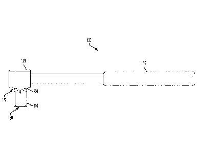
FIG. 1 is a side view of a tool incorporating an embodiment of the present
invention.
FIG. 2A is a first side view of a drive lug of a tool incorporating an
embodiment of the
present invention.
2
55502413v.2
Date Recue/Date Received 2020-06-04
FIG. 2B is an end view of the drive lug of FIG. 2A.
FIG. 2C is a second side view of the drive lug of FIG. 2A.
FIG. 2D is a perspective side view of the drive lug of FIG. 2A.
FIG. 3 is a side view of another drive lug incorporating an embodiment of the
present
invention.
Detailed Description of the Embodiments
While this invention is susceptible of embodiments in many different forms,
there is
shown in the drawings, and will herein be described in detail, a preferred
embodiment of the
invention with the understanding that the present disclosure is to be
considered as an
exemplification of the principles of the invention and is not intended to
limit the broad aspect of
the invention to embodiments illustrated. As used herein, the term "present
invention" is not
intended to limit the scope of the claimed invention and is instead a term
used to discuss
exemplary embodiments of the invention for explanatory purposes only.
The present invention broadly relates to a torque application tool, such as a
ratchet tool,
having a handle and a ratchet head extending from the handle, the ratchet head
may include a
cavity with a drive gear having circumferentially disposed gear teeth and one
or more pawls
adapted to selectively engage the gear teeth. The tool includes a drive lug
adapted to accept and
couple to sockets and other fastener engaging work pieces. The drive head
includes a groove
with a predetermined diameter formed on the drive lug. The diameter of the
groove is
predetermined to cause the drive lug to fail through torsional ductile
fracture before an internal
mechanism (including the gear and/or the pawl) fails or otherwise damages the
tool.
As a result of these improvements, feedback can be provided to a user of the
tool to alert
the user that the tool is failing before a sudden fracture occurs, due to the
ductile twist of the
3
55502413v.2
Date Recue/Date Received 2020-06-04
drive lug. This substantially reduces damage and/or failure of the internal
(gear or pawl)
structure of the tool.
Referring to FIGs. 1 and 2A-2D, a tool 100, such as a ratchet tool, is
illustrated. The tool
100 may include a handle 110 and a ratchet head 120 coupled to and extending
from the handle
110. The ratchet head 120 extends from the handle 110, and may include a
cavity (not shown) to
house internal ratcheting components including a gear having circumferentially
disposed gear
teeth and pawl(s) adapted to selectively engage the gear teeth.
For example, the ratchet head 120 includes a ratcheting mechanism including
one or
more pawls (not shown) and gear 130 with gear teeth. The interaction between
the pawls and
gear teeth allow a user to rotate the tool 100 in a first rotational
direction, in which the pawl
engages the gear teeth to apply a torque. The interaction between the pawls
and gear teeth allow
a user to rotate the tool 100 in a second rotational direction, opposite the
first rotational direction,
in which the pawl disengages the gear teeth and ratchets or slips about the
gear 130 when the tool
100 is rotated in the second rotational direction.
The gear 130 may be formed integrally with a drive lug 140 that is adapted to
engage and
couple to a socket or other fastener engaging work piece. For example, the
drive lug 140 may
include a detent mechanism 150 for retaining a selected one of a plurality of
interchangeable
wrench sockets. The detent mechanism 150 may be an outwardly biased ball
disposed on the
drive lug 140. The ball may be outwardly biased by a bias member, such as a
spring.
As illustrated, the drive lug 140 has a substantially square cross-sectional
shape.
However, the drive lug 140 may have any desired cross-sectional shape, such as
triangular,
pentagonal, hexagonal, or any other geometric shape as desired.
4
55502413v.2
Date Recue/Date Received 2020-06-04
The drive lug 140 includes a groove 160 with a predetermined diameter D. The
drive lug
140 includes a first end portion 170 proximate the ratchet head 120 of the
tool 100 and a second
end portion 180 distal from the ratchet head 120 of the tool 100. The groove
160 is formed on
the drive lug 140 between the first end portion 170 and the second end portion
180, and proximal
to the first end portion 170. The groove 160 is formed to promote failure of
the drive lug 140
prior to failure of other components of the tool 100, such as the ratchet
mechanism (the pawl(s)
and/or gear 130).
Referring to FIG. 2A, the predetermined diameter D includes a minimum diameter
across
the groove 160. The diameter D is determined to promote failure of drive lug
140 rather than
failure of the ratchet mechanism, such as gear failure or pawl failure. To
achieve this, the
diameter D is determined based on torsional failure of a cylinder and/or polar
moment directed to
the design of the tool 100. A polar moment of inertia, also known as second
polar moment of
area, is a quantity used to describe resistance to torsional deformation
(deflection) in cylindrical
objects (or segments of cylindrical objects) with an invariant cross-section
and no significant
warping or out-of-plane deformation.
In one aspect, the diameter D is a diameter of a cylinder that torsionally
fails at a same
load as a drive lug for which the tool or a ratchet mechanism of the tool is
designed. Another
way to express the diameter D is that the diameter D is a diameter of a circle
with a same second
polar moment of area as a square section of a drive lug for which the ratchet
mechanism is
designed.
For example, for the drive lug 140 with sides of length x, the second polar
moment ./
- square
is:
Jsquare ¨ X416
5
55502413v.2
Date Recue/Date Received 2020-06-04
For a circle with a diameter of D, the second polar moment Jcirde is:
JcIrde= RD4/32
Thus, for equivalent polar moments:
JcIrde ¨ Jsquare
704/32 = x4/6
D4 = 32x4/67r
WTI I 4 32X4 V2 /x4
.\
6ir 6ir
D = 1.1415x
For example, the drive lug 140 may be a 3/8 inch square on a 1/4 inch tool
100. In this
example, the groove 160 may have a diameter D of about 0.285 inches. The drive
lug 140 may
have a length Li (measured from a center of the groove 160 to the second end
portion 180) of
about 0.369 inches, and a length L2 (measured from a center of the groove 160
to a center of a
detent 150) about 0.183 inches. In this example, the groove 160 has a radius
of curvature R of
about 0.031, and provides an angle of al of about 30 degrees, and an angle a2
of about 15
degrees.
While the groove 160 is shown and described as having a circular cross
section, the
groove may have other cross sectional shapes, with an equivalent diameter of
the other shape
being used to determine the appropriate failure point. For example, Referring
to FIG. 3, the gear
130' may be formed integrally with a drive lug 140' that is adapted to engage
and couple to a
socket or other fastener engaging work piece. For example, the drive lug 140'
may include a
detent mechanism for retaining a selected one of a plurality of
interchangeable wrench sockets.
The detent mechanism may be an outwardly biased ball disposed on the drive lug
140'.
6
55502413v.2
Date Recue/Date Received 2020-06-04
The drive lug 140' includes a groove 160' formed between a first end portion
and a
second end portion, and proximal to the first end portion. The groove 160' may
have a
substantially square cross-sectional shape, and still be formed to promote
failure of the drive lug
140' prior to failure of a ratchet mechanism (the pawl(s) and/or gear) of the
tool.
While the groove is described as being implemented in a drive lug of a ratchet
wrench, it
should be understood by those skilled in the art, that the present invention
is not necessarily
confined thereto but, rather, is applicable to a wide variety of ratchet
mechanisms and other tool
application tools. For example, the groove may be implemented in a drive lug
or drive end of a
screwdriver type tool, an electronic ratchet wrench, an impact wrench, a
breaker bar and any
other tool that has a driving end and internal components that are desired to
be protected from
sudden failure.
As used herein, the term "coupled" and its functional equivalents are not
intended to
necessarily be limited to direct, mechanical coupling of two or more
components. Instead, the
term "coupled" and its functional equivalents are intended to mean any direct
or indirect
mechanical, electrical, or chemical connection between two or more objects,
features, work
pieces, and/or environmental matter. "Coupled" is also intended to mean, in
some examples, one
object being integral with another object.
The matter set forth in the foregoing description and accompanying drawings is
offered
by way of illustration only and not as a limitation. While particular
embodiments have been
shown and described, it will be apparent to those skilled in the art that
changes and modifications
may be made without departing from the broader aspects of the inventors'
contribution. The
actual scope of the protection sought is intended to be defined in the
following claims when
viewed in their proper perspective based on the prior art.
7
55502413v.2
Date Recue/Date Received 2020-06-04