Note : Les descriptions sont présentées dans la langue officielle dans laquelle elles ont été soumises.
WO 2019/106700 PCT/1T2018/050213
KIT FOR CONSTRUCTING DRY-MOUNTED WALLS
DESCRIPTION
Field of Application
The field of constructions and masonry together with the field of
construction toys are the main fields of application of this invention, but
not
the only ones; from these fields terminology and examples are taken,with an
explanatory and non restrictive aim.
The main objective of this invention is the creation of a kit for the
construction of dry-mounted walls having an innovative modality of
resistance to earthquakes,
Another innovative characteristic of this invention is the form of the
modular element, which allows the easy and cheap creation of any single
piece, making industrially profitable its production.
State of the art
The benefits of the dry-mounted self-standing walls assembled in a
diamond configuration, that is the inclination at 45 of the internal faces
of the elements from the horizontal plane, have already been disclosed
by previous patents, mainly Patent Blair U.S. 3238680 and Patent
Henderson U.S. 4429506, which illustrate in detail its benefits and
advantages, such as the way to implement it on field. These patents have
the main aims of facilitating and standardizing the processes of
construction and reducing their related problems. The solutions disclosed
by these patents do not tackle directly the possibility of optimising the
resistance of their products to earthquackes that could compromise their
utilization and actually they provide indirectly to this problem the standard
solution of blocking the elements once in place, by grouting the
Date recue/ date received 2021-12-23
WO 20191106700
PCT/1T20181050213
elements (Pat. Blair) or by creating male/female joints shaped in order to
block completely any movement once definitely in place (Pat.Henderson).
The attempt of a solution has been done by me, filing the Italian patent
request nr. 102017000002158, rejected because considered as lacking of
novelty; this file identifies a possible innovation in joining the diamond
configuration with a different sort of joints allowing the elements to move,
but it remains in the generality of the assumption, without providing any
concrete solution for granting the proper movement, and without
proposing the insertion of pins and groves into the internal faces of the
elements, solution that is proposed now and of which the
protection in claimed in this patent request.
Furthermore the complexity of all previous solutions makes expensive their
industrial production and jeopardise their diffusion.
Presentation of the invention.
According to an aspect of the invention there is provided a kit for the
realization of a dry mounted, self-supporting, anti-seismic, modular structure
comprising
- at least one polyhedric bar having at least one face,
- a plurality of modular elements having the shape of a parallelepiped with
two
bases and four faces extending between the bases, and
- a plurality of junction elements each having the shape of the section which
would be obtained when cutting said modular elements along a diagonal of
one of their bases, the plurality of junction elements having two bases and
three faces extending between the bases,
whereby said bars, modular elements and junction elements have at least one
female element and/or one male element on at least one of their faces, shaped
so as to be coupled with play with the male/female element of a contiguous
2
Date Re9ue/Date Received 2021-07-22
WO 2019/106700 PCT/IT2018/050213
element, whereby the female elements have a groove shape and the male
elements have a pin shape apt to be inserted and to slide along said grooves
once
in place, and whereby, in said modular elements and said junction elements,
the
grooves run parallel to the bases, whereby said bars, modular elements and
.. junction elements can be connected and assembled together in absence of any
sort
of binder or joint, and whereby the bases of said modular elements and said
junction elements can be assembled in static equilibrium with a diamond
configuration along a plane parallel to the direction of the force of gravity,
such
that
- any single modular element and junction element is connected with play to a
contiguous element and remains free to move also once in place,
- all the faces of the modular elements in contact with the faces of other
modular
elements or junction elements identify reciprocal, non-horizontal, sliding
planes
transverse to the direction of the force of gravity.
S According to another aspect of the invention there is provided a dry
mounted,
self-supporting, anti-seismic, modular structure constructed with the use of a
kit
according to the previous aspect of the invention.
According to yet another aspect of the invention there is provided a process
of
constructing a dry mounted, self-supporting, anti-seismic, modular structure
using
a kit according to the initially recited aspect of the invention.
The core of the novelty and the inventive step of this process for
constructing
walls is the abandoning of the concept of self-supporting wall as a solid and
compact structure.
We get this through the elimination of both the binders and the locking
joints, the positioning of the elements using the diamond configuration and
the
2a
Date Re9ue/Date Received 2021-07-22
WO 2019/106700 PCT/IT2018/050213
creation into the elements of a system of grooves and pins which, when in
place, do not block the elements but keep them free to move, in case of
thrusts
or quakes, always aligned with the axis of the wall, along the system of
transversal planes created by the surrounding
elements
2b
Date Re9ue/Date Received 2021-07-22
CA 03083446 2020-05-25
WO 2019/106700
PCT/IT2018/050213
with the diamond configuration.
This transversal planes transform any sort of thrust, into an upwards
transversal thrust, always hampered by the force of gravity and the
weight of the structure; at the end of the stresses the force of gravity will
sreposition each element in its original position, at the center of the wedge
created by the underlying elements, using the same transversal planes.
This actions of repositioning the elements along the transversal planes
back to their original position utilising the force of gravity is part of the
inventive step and it is not possible on horizontal planes and if elements
ioare locked.
In addition to creating an extremely ergonomic basic element, functional
to the purpose and industrially reproducible, the novelty and inventive
step of this process of drywall construction is found in the identification,
definition and use of four conditions, all necessary and sufficient to
iscreate what we could call a "moving wall", a wall that "must" be able to
move, to hinder the seismic shakes and the major thrusts in a way that
has to be considered inventive and innovative in the process of building
vertical walls.
These four conditions are:
201) the shape of the elements and their correct positioning,
2) the shape of the grooves and pins that, while avoiding the locking
3
SUBSTITUTE SHEETS (RULE 26)
CA 03083446 2020-05-25
WO 2019/106700
PCT/IT2018/050213
joints, maintain their function of guide,
3) the diamond configuration of the elements, which allows the creation
of wedges and transverse planes and the consequent absence of
horizontal planes, which are identified as a major problem to be avoided
sin this construction technique,
4) the dry construction, free of binders and free of locking joints, which
prevents the solid welding of the elements once in place, keeping them
in a static equilibrium.
The result of this invention is a dry-mounted wall, assembled in a
iodiamond configuration composed of modular elements, their related
completion elements and the containment bars and pillars.
The modular element is a six faces parallelepiped having a squared or
rhomboid basis; the height of the parallelepiped when positioned will be
the thickness of the wall and its basis will constitute the two facades of
isthe wall. In the diamond configuration the two diagonals of its basis are
disposed vertically and horizontally. When in its final position the
element has two external parallel faces placed vertically, two internal
faces laying upwards and two internal faces laying downwards. Into two
contiguous internal faces two pins are inserted per each face, disposed at
2othe same height and at the same distance from their closest external face,
simmetrically (FIG.1,2,7).
The two opposite contiguous internal faces have two grooves each,
laying symmetrically in correspondence of the pins which are on the
opposite faces (FIG.1,3,7,8); starting from the edge in common between
4
SUBSTITUTE SHEETS (RULE 26)
CA 03083446 2020-05-25
WO 2019/106700
PCT/IT2018/050213
the two faces, these grooves run along the faces in parallel with the
external face of the element, for its entire length (FIG.1,3) or just to the
height of their matching pins (F1G.7,8); these grooves will always be
slightly wider than the thickness of the forecasted pins, and slightly
sdeeper than their height, in order not to block or stress or press or strain
anyhow the pins when the elements are assembled in their final position
of static equilibrium. The force of gravity and the friction between the
elements in the diamond configuration will grant the stability of the wall;
the pins, together with the friction between the opposite faces, will
I hinder the thrusts avoiding the misalignment of the wall along the axis of
the facade. When assembling the elements, both faces holding pins have
to face upwards or both downwards and in the same way for all the
elements of that wall. For technical reasons the number of pins, their
shapes, materials and/or dimensions may vary, provided that the
iscorresponding grooves are matching the selected pins.
These characteristics make the production of the elements extremely
cheap: the initial form to be created is a plain six faces block, into which
you just have to carve the grooves and to insert the pins. With many
materials grooves may be already forecasted when preparing the mold
20and, for materials such as concrete or conglomerates, pins may be
replaced by metal bars inserted into the mold, having one extremity
remaining external to form the pin and the internal part utilised to
reinforce the concrete. When using materials such as wood, pins allow to
reduce wastage due to the carving and increase the resistance of the male
25j0int in front of thrusts and stresses; for wood, so much as for many
SUBSTITUTE SHEETS (RULE 26)
CA 03083446 2020-05-25
WO 2019/106700
PCT/1T2018/050213
other materials, a pin inserted in an element, even if the two of them are
composed of different materials, provides a much higher endurance in
front of thrusts and stresses than a pin carved from the same piece. The
specific materials utilised for pins and for elements will determine
sdimensions, profile, shape, height and thickness of pins.
In the proposed sample, the modular element is a square basis block with
dimensions 70x70x100 mm (millimiters), excluding pins; its volume is
490 cc (cubic centimeters), excluding the variations due to pins and
grooves. The four internal faces measure 70x100 mm and 100 mm is at
iothe same time the length of the basis of the internal faces, the length of
the vertical section and the thickness of the element when in its correct
position. The two external faces measure 70x70 mm, and their diagonals
both are 70-Ni2, that is 98,9 mm, which can be considered as 100,
because of the tolerances of materials; therefore vertical and horizontal
issections in place can be considered as 100x100mm. The volume of
almost half a cubic decimeter and the 100x100mm section make easy
many evaluations and rough calculations also for unskilled labor; due to
the diamond configuration, any layer of elements will raise the wall by
50 mm and its 100 mm thickness can be increased by 50 mm a time, by
20p1acing aside entire elements or halves of them, alternately. The dry
construction technique makes all these measures compatible with those
of the constructions requiring mortars or binders, so allowing the
utilisation of all the finishing, the tools and the accessories already in use
in the construction sector.
25The squared basis, the element dimensions and the proportions between
6
SUBSTITUTE SHEETS (RULE 26)
CA 03083446 2020-05-25
WO 2019/106700
PCT/IT2018/050213
its parts may be varied in case of technical or aestetic needs.
Grooves are 10 mm large and their depth is 20 mm; any of them is 20
mm distant from its closest external face and 40 mm distant from the
other groove. The external part of pins is 8 mm thick and 19 mm high.
sApart from minimising the production costs, the form of these elements,
the shape of their joints and the diamond configuration allow an
innovative reaction of the structure to earthquakes.
In a compact construction quakes release their energies over the weakest
points of the structure; in this kit of construction the wall does not hinder
iothe shake as a compact ensamble: on the contrary, any single element
remains free to move; the enormous earthquake forces are parcelled in
vectors aligned to the form and the positioning of the elements and they
discharge their forces on any single element, causing their movement.
The dry building technique allows the pieces movement, and the specific
isplay created by pins and grooves forces elements to slide like cars over
their rails, uniquely in a direction aligned to the axis of the facade and
trasversal to the ground due to the diamond composition, while the two
parallel grooves minimise the possibility of swinging and the risk of
misalignment of the single elements, which are forced to slide and climb
2oalong the planes created by the contiguous elements, transforming all the
strains into transversal and ascensional thrusts always hindered by the
force of gravity that, at the end of the quakes, will reposition any single
element at the center of its wedge in the diamond composition, bringing
back the entire structure in the original position of static equilibrium.
25The downwards positioning of pins and the upwards positioning of
7
SUBSTITUTE SHEETS (RULE 26)
CA 03083446 2020-05-25
WO 2019/106700
PCT/IT2018/050213
grooves contribute to lower the barycenter of the element and help its
balance during movements. The weight of the structure, the undulatory
and discontinuous nature of the shakes and the continuous detachments
of any single element from at least one of the contiguous ones, will tend
5t0 parcel and hinder constantly the effects of the thrusts and the wall will
react to eartquakes in a way which is much more similar to the reaction
of gravel terrains than the reaction of the compact ones, dispersing the
forces instead of discharging them against the weakest points.
Apart from the eartquakes, in which forces and thrusts are exceptional,
iothe wall will maintain all the characteristics of static equilibrium and
stability given by the dry-mounted building with diamond configuration
already illustrated in the previous patents.
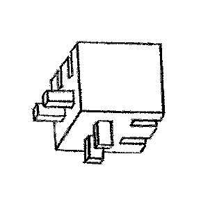
Finishing elements: being the modular elements set in a diamond
configuration, finishing elements are junction elements connecting them
isto the basement (FIG 4), to lateral pillars (FIG 5) and with the top of the
wall or the ceiling (FIG 6); they are also used to create doors, windows
or technical holes for cabling or plumbing; they are obtained by dividing
the modular element along one or more of its axes; their use is of
immediate understanding (FIG 9-10-11). The section in two halves along
2othe plane parallel to the external face results in two symmetrical pieces
that can be use to enlarge the thickness of the walls by multiples of 50
mm. These finishing elements may have additional pins along the faces
obtained by the splitting, allowing the anchoring to the facing elements
(FIG 5), or allowing to satisfy technical needs (FIG 9-11).
25Containment elements: they are poligonal pillars into which other
8
SUBSTITUTE SHEETS (RULE 26)
CA 03083446 2020-05-25
WO 2019/106700
PCT/IT2018/050213
elements can be anchored or leant: differently from the rest of the
construction, they can be fastened to the ground or to the basement; one
or more lateral faces have male or female joints matching those of the
elements used. In case of grooves, they will run vertically and they are
sintended to transform the transversal thrusts into vertical ones allowing
the finishing elements to make a vertical sliding movement which will
lift the element, avoiding the possibility of being crashed by other
elements, uplifting its contiguous elements upwords and so discharging
its lateral thrusts. As closing elements, U shaped bars can be used,
iohaving joints or not; these bars have been already illustrated and they are
part of the state of the art.
Many variants of the modular elements can be forecasted, such as two
different elements, one with all male joints and one with all female
joints, to be laid alternately, or having other variants with more than two
isdifferent elements having different shapes, creating different
configuration with the same sort of joints, grooves and pins and without
horizontal planes, always allowing any element to move, remaining
within the perimeter of the invention.
Dimensions, colors, the sort of material utilized, the fact of being
2ointemally empty or compact or having any sort of holes, cavities or
canalizations, the fact of being homogeneous or stratified or composed
by one or more materials, all these are irrelevant details for the
functionality of the process over which we claim the protection of the
patent and may vary as per the needs or the requests.
25A11 the elements utilized in the work should have dimensions,
9
SUBSTITUTE SHEETS (RULE 26)
CA 03083446 2020-05-25
WO 2019/106700
PCT/IT2018/050213
proportions, faces, joints, contact faces and profiles that must be
compatible and matching with the modular element utilized; therefore
for any modular element "A", it will be necessary to create a "Type A"
set of finishing elements having all the requested characteristics
scompatible with "A". In future the development of this building
technique will multiply the possible variety of elements, designed to
solve specific problems or aesthetic necessities, always remaining in the
perimeter of the invention.
As per what we have explained until here, it seems evident that the
process reaches its goals. The means of the process may have
innumerable variations, all within the border and the perimeter of the
invention and included into the attached claims. Any detail can be
changed with other elements technically equivalent and materials will be
diversified as per the local needs without going out of the protection of
isthe requested patent. Even if elements are described referring
specifically to the attached figures, the figures themselves and the
reference numbers used in the description and in claims have to be solely
intended as mere means for better understanding the process and they are
not intended to put any limit to the protection claimed with the requested
2opatent.
Brief description of pictures:
Further characteristics, features and benefits of the invention will
become evident after the clarification of the detailed illustration of
figures, representing two main non-exclusive examples of the basic
25e1ement and of their related finishing elements.
SUBSTITUTE SHEETS (RULE 26)
CA 03083446 2020-05-25
WO 2019/106700
PCT/IT2018/050213
Fig 1-2-3 : perspective views of a modular element having grooves
running along the entire upper faces.
Fig 4-5-6 : perspective views of the related finishing elements, to be used
for the basement (FIG 4), for finishing lateral edges (FIG 5) or the top
s(FIG 6), obtained by splitting the elements.
Fig 7-8 : perspective views of a modular element having grooves running
partially along the upper faces.
Fig 9 : perspective view of the beginning of the construction of the wall
starting from the lateral pillar and the finishing elements.
ioFig 10 : perspective view of a pillar having four faces with vertical
grooves as female joints.
Fig 11: perspective view of the beginning of the construction of the wall
starting from the lateral pillar with the finishing elements and a first row
of modular elements in place.
20
11
SUBSTITUTE SHEETS (RULE 26)