Note : Les descriptions sont présentées dans la langue officielle dans laquelle elles ont été soumises.
CA 03084982 2020-06-05
WO 2019/118561
PCT/US2018/065132
APPARATUS, SYSTEM, AND METHOD FOR TISSUE REGENERATION
BACKGROUND
The present invention relates to an apparatus, system, and method for
regenerating
tissue such as the pelvic floor musculature.
Tissues of humans and animals are able to regenerate or repair themselves and
thus
enable stressed, injured, or damaged tissues, that cause underlying
undesirable
conditions such as incontinence, to repair themselves and thus eliminate the
undesirable condition. The present invention utilizes low, medium or high
vibrations
to create a regenerative or repair environment for tissues.
Regeneration or repair of tissue generally consists of three phases:
inflammation,
repair, and maturation. When a tissue is injured the cells are either quickly
repaired or
undergo necrosis (rupturing of the cell membrane and release of its
intracellular
contents). When there is an injury the body initiates or induces inflammation,
which is
required for the regeneration phase. Inflammation causes neutrophils and
macrophages
to arrive at the site of the injury. Neutrophils and macrophages are
responsible for the
phagocytosis of dead cell debris and for the production of the anti-
inflammatory
cytokines required for the down-regulation of the inflammatory response that
prevents
further damage.
The regulation of this inflammatory response has been described in many
tissues,
including skeletal muscle and is ultimately responsible for the passage from
an injured
1
CA 03084982 2020-06-05
WO 2019/118561
PCT/US2018/065132
tissue environment to one of tissue repair. During the tissue repair process
the tissue
cells go through maturation, which is the last phase of regeneration.
Maturation results
in the consolidation of differentiated cells that acquire a functionally
mature phenotype.
As one might suspect, the inflammation, differentiation and maturation phases
differ
from tissue to tissue.
Tissues can also be repaired by the application of mechanotransduction
therapy.
Mechanotransduction therapy applies vibrations to the tissue in order to cause
a
physical change in the tissue. The mechanical forces or stress are converted
by the cell
into intra-cellular signaling and biochemical reactions that permit the cells
of the tissue
to repairs themselves.
As a mechanical stress is applied to the tissue the cytoskeleton of the tissue
cells
increases in stiffness in response to the forces acting on different focal
adhesion sites.
The cell is able to transmits the force or stress, e.g. actomyosin or other
myosin motors
that may generate tension in the cytoskeleton. The fibrous scaffolds are then
able to
transmit the stress or tension over long distances.
The mechanical stress both cause deformation nuclear envelope, other stress
sensing
structures within cells and on the surrounding extracellular matrix (ECM). The
cell
then activate gene expression, produce new proteins and remodels the ECM that
comprises its tissue microenvironment in a load-dependent manner. As the ECM
microenvironment changes to repair the cell, the viscoelasticity properties of
the tissue
is repaired.
Any tissue may be treated by the present invention. One particular group of
muscles
2
CA 03084982 2020-06-05
WO 2019/118561
PCT/US2018/065132
that can be treated by the mechanotransduction properties of the present
invention is
the pelvic floor muscles. The pelvic floor muscles are a mind-controlled and
layered
muscle group which surrounds the urethra, vagina, and rectum, and which,
together
with the sphincter muscles, functions to control these openings. This
musculature also
serves to support the urethra, bladder, and uterus, as well as to resist any
increases in
the abdominal pressure developed during physical exertion. The muscle group
includes both longitudinal muscles and annular muscles.
Training of the pelvic floor musculature has proven efficient in preventing
and treating
several conditions, e.g. incontinence. Numerous exercises exist for training
the pelvic
floor musculature. For a number of reasons, the effect of these exercises
varies among
people. Also, it is known that mechanical vibrations in a range below approx.
120 Hz
applied to the tissue increase the training effect of such exercises. As the
musculature
becomes stronger, it will be possible to measure the training effect by
measuring the
ability of the musculature to retract.
Measuring principle and measurement parameters
A stronger muscle can be expected to dampen an amplitude of oscillation
applied
thereto more than a weaker muscle. A first principle of measurement,
therefore, may
be to measure the amplitude dampening of an imposed oscillation. The measured
amplitude can be described as A ¨ Aosin(wt). A relative amplitude dampening is
defined as: where
AA= (A-Ao)/Ao (1)
A is the amplitude measured,
Ao is the amplitude imposed,
3
CA 03084982 2020-06-05
WO 2019/118561
PCT/US2018/065132
wis the angular frequency of the oscillation imposed, and
t is time.
It is considered well known to a person skilled in the art that the output
signal from an
accelerometer may represent an acceleration which can be integrated to obtain
a
velocity and a second time to obtain a displacement or deflection. It is also
well known
that accelerations, velocities, and displacements of equal magnitudes and
opposite
directions have average values of zero, and that meaningful parameters hence
must be
based on absolute values such as maximum acceleration, velocity, or amplitude,
for
example. In view of the above, it is clear that the dimensionless attenuation
AA can be
calculated from displacements in mm, velocities in m/s, accelerations in m/s2
, and/or
electrical signals input to the oscillator and output from the accelerometer.
In any case,
the attenuation AA can be expressed in dB, calibrated to display the force in
Newton
(N), etc. according to need and in manners known for persons skilled in the
art.
During normal exercise, the volume of the muscle cells increases and the
skeleton of
the cells becomes more rigid. In another model, therefore, the pelvic floor
musculature
can be regarded as a visco-elastic material, i.e. as a material having
properties between
a fully elastic material and an entirely rigid and inelastic (viscous)
material. For
example, a slack or weak muscle can be expected to exhibit relatively
"elastic"
properties, whereas a tight or strong muscle can be expected produce more
resistance
and thus relatively "viscous" properties. Formally:
stress is the force acting to resist an imposed change divided by the area
over
which the force acts. Hence, stress is a pressure, and is measured in Pascal
(Pa), and
- strain is the ratio between the change caused by the stress and the relaxed
4
CA 03084982 2020-06-05
WO 2019/118561
PCT/US2018/065132
configuration of the object. Thus, strain is a dimensionless quantity.
The modulus of elasticity is defined as the ratio X= stress/strain. The
dynamic
modulus is the same ratio when the stress arises from an imposed oscillation.
When an oscillation is imposed in a purely elastic material, the elongation
measured is in phase with the imposed oscillation, i.e. strain occurs
simultaneously
with the imposed oscillation. When the oscillation is imposed in a purely
viscous
material, the strain lags the stress by 900 (7c/2 radians). Visco- elastic
materials
behave as a combination of a purely elastic and a purely viscous material.
Hence,
the strain lags the imposed oscillation by a phase difference between 0 and
7c/2.
The above can be expressed through the following equations:
U = a osin (cot) (2)
E = E0 sin(wt¨ 0) (3)
A = a/e (4)
where
a is stress from an imposed oscillation (Pa)
8 is strain (dimensionless)
w is the oscillator frequency (Hz)
t is time (s),
il) is the phase difference varying between 0 (purely elastic) and 7c/2
(purely
viscous), and A is the dynamic module.
5
CA 03084982 2020-06-05
WO 2019/118561
PCT/US2018/065132
Biomechanically, this may be interpreted as that a stronger muscle increases
the force
resisting the oscillation and thereby "delays" the vibrations measured by the
accelerometer. This is equivalent with that a strong muscle is stiffer or
"more viscous"
than a slack, gelatinous, and "more elastic" muscle.
A general problem in the prior art in the field is that devices, methods, and
systems fail
to properly apply mechanotransduction therapy and then fail to properly and
accurately
record the therapy results. For example, patients present with various and
unique
anatomy. The vaginal canal, or instance, of patients can vary greatly due to
genetics,
injury, age and the like. Therefore, a therapy device for one patient may not
necessarily
be the best therapy device for another patient.
Another problem with the prior art is that measurement values are often given
in terms
of pressure, e.g. in millimeter water column. As pressure is a force divided
by an area,
the pressure reported will depend on the area of the measuring apparatus, and
hence on
the supplier. Therefore, in the literature in the field, measurement values
are often given
in the format '<Supplier_name> mmH20', for example. In turn, this results in
that
measurement values from different apparatuses are not directly comparable, and
consequently a need exists for supplier independent measurement values in the
field of
the invention.
US 6,059,740 discloses an apparatus for testing and exercising pelvic floor
musculature.
The apparatus includes an elongate housing adapted for insertion into the
pelvic floor
6
CA 03084982 2020-06-05
WO 2019/118561
PCT/US2018/065132
aperture. The housing is divided longitudinally into two halves, and includes
an
oscillator as well as a cut out and equipment for measuring pressure applied
to the
housing halves from the pelvic floor musculature. The apparatus indicates the
force
pressing together the two halves in Newton (N), and essentially measures the
training
effect on muscles acting radially on the housing.
A need exists for an apparatus that may be adapted to various and unique
anatomy so
that therapy may be properly applied.
Another need exits that measures and trains the musculature running in
parallel with a
longitudinal direction of the apparatus or pelvic floor opening.
The object of the present invention is to address one or more of the above
problems,
while maintaining the advantages of prior art.
SUMMARY OF THE INVENTION
According to the invention, this is achieved by an apparatus, system, and
method for
tissue regeneration.
The present invention includes a housing that is adaptable for a particular
site or
location of treatment. For instance, the housing may be generally curved or
pliable to
enable it to be applied to an arm or leg in order to treat the epidermis or
skeletal muscle
of a patient. The housing may able be generally planar and/or pliable to
permit it to be
applied to a back, chest or abdomen of a patient in order to treat the back,
chest,
abdominal epidermis and skeletal muscles.
7
CA 03084982 2020-06-05
WO 2019/118561
PCT/US2018/065132
In another embodiment of the invention, the housing may be generally elongate
and
selectively adapatable or adjustable prior to or after inserting into an
orifice or opening
in a patient. Such openings include but are not limited to a pelvic floor
opening to treat
the pelvic floor muscles or tissue, rectal openings, urethral openings, and
openings of
the ears, nose and throat. Openings may also include surgical site openings.
For
instance, during the surgical treatment of internal organs such as the liver,
lungs,
bladder, kidneys, pancreas, heart, and brain.
The housing may include an adaptable or adjustable exterior that enables it to
be
selectively adjustable to engage or contact a tissue to be treated. In another
example
embodiment, the adjustable housing may cause continuity of tissue contact
between
various layers of tissues in proximity to each other in order to permit
effective
mechanotransduction therapy through the number of tissue layers.
The housing may include one or more mechanotransduction generators that are
capable
of creating a tissue regeneration response or environment in the selected
tissue. In one
example embodiment, the mechanotransduction generator may include an
oscillator
capable of generating a vibration signal and an accelerometer for reading the
vibration
signals from the oscillator. The accelerometer may be connected to a signal
processor
configured for communicating signals representative of values read from the
accelerometer.
The use of an accelerometer for measuring a response makes it possible to use
a closed
housing, simplify the remaining construction, and increase the accuracy of the
8
CA 03084982 2020-06-05
WO 2019/118561
PCT/US2018/065132
measurements. It is also possible to calculate a relative amplitude
attenuation, phase
delay, and/or dynamic modulus in one or more dimensions. These parameters,
combined
or individually, can be used for characterizing the musculature in a more
accurately and
detailed manner than is possible with the prior art.
Also, imposing oscillations and/or measuring responses along several axes
allow the
adaptation of training and testing to specific muscle groups in the pelvis
floor.
In another aspect, the present invention relates to a system using such an
apparatus
with a controller configured for controlling the frequency and/or amplitude of
the
oscillation. The system is characterized in that it further includes a control
module
configured for determining an oscillator parameter within at least one time
interval,
and for providing the oscillator parameter to the controller; a data capturing
module
configured for receiving a response from the accelerometer and calculating a
result as a
function of the oscillator parameter and the received response; an analysis
module
configured for calculating at least one group value based on a series of
measurements
of oscillator parameters and the results thereof; a data storage configured
for storing
and retrieving at least one data value from a group consisting of the
oscillator
parameters, response, calculated result, and group value; and communication
means
configured for conveying the data value between the modules and the data
storage.
In a third aspect, the present invention relates to a method for using
mechanotransduction to treat, testing, and exercise tissue, such as the pelvic
floor
musculature, wherein an oscillation is imposed on the musculature,
characterized by
measuring the response from the musculature using an accelerometer and
9
CA 03084982 2020-06-05
WO 2019/118561
PCT/US2018/065132
characterizing the musculature based on the response to the oscillation
imposed.
Suitable measurement parameters, such as the relative amplitude attenuation,
phase
delay, and/or dynamic modulus, may indicate, among other things, force and/or
elasticity of various muscle groups in the pelvic floor.
In a preferred embodiment, the tissue or musculature is imposed an oscillation
of a
frequency equal or close to the maximum response frequency during training of
the
musculature. The maximum response frequency is assumed to change over time,
and
may be, inter alia, displayed and/or logged in order to document training
effect, alone
or in combination with one or more other parameters.
In another embodiment of the present invention, mechanotransduction therapy
applied to
the pelvic floor has been shown to foster a regenerative environment, and
"jump-start"
the proliferation and differentiation of stem cells for various types of
tissues. In order
for mechanotransduction to be the most effective, there must be enough tension
in the
pelvic floor to achieve sufficient mechanotransduction signaling. This tension
may be
achieved by voluntarily contracting the pelvic floor musculature. The tension
can be
further supplemented if using a barrier, similar to any of the embodiments
disclosed
herein, which provide a greater surface area for tissue compliance. In one
embodiment of
the invention, electrodes may be used to cause tissue pre-tensioning.
Additional features and embodiments will be apparent from the attached patent
claims.
10
CA 03084982 2020-06-05
WO 2019/118561
PCT/US2018/065132
BRIEF DESCRIPTION OF THE DRAWINGS
The invention will be described in more detail in the detailed description
below with
reference to the appended drawings, in which:
Fig. 1A is a longitudinal schematic section of an apparatus;
Fig. 1B is a longitudinal schematic section of an apparatus;
Fig. 1C is a longitudinal schematic of an apparatus;
Fig. 2 illustrates alignment of a triaxial accelerometer in the apparatus of
Fig. 1A;
Fig. 3 (prior art) shows the principle of an oscillator;
Fig. 4 (prior art) shows the principle of an accelerometer;
Fig. 5 is a schematic illustration of a system according to the invention;
Fig. 6 is a schematic depiction of the functions of the system;
Fig. 7 is a flow diagram illustrating a method according to the invention;
Figs. 8A-8D illustrate a more detailed embodiment of the signal processor
according to the invention; and
Figs. 9A-9B illustrate a cross section of an expandable housing.
DETAILED DESCRIPTION
Fig. 1A is a longitudinal schematic section of an apparatus 100 according to
the
invention. The apparatus is comprised of an elongate, cylindrical housing 101,
which can be made of a relatively rigid plastic material. Advantageously, an
outer
casing 102 made of medical silicone can be provided on the outside of housing
101.
11
CA 03084982 2020-06-05
WO 2019/118561
PCT/US2018/065132
The size of the housing is adapted for an opening in the pelvic floor.
In an example embodiment of the invention, housing 101 may have a selectively
adaptable or adjustable outer casing 102 that enables it to expand to engage
or
contact a tissue surface to be treated. As particularly illustrated in the
example
embodiment of Fig. 1A, the outer casing 102 may be expandable between a
resting
state and an expanded state, which is generally characterized by having a
larger
circumference and/or length than a in the resting state.
Referring to Fig. 1B, housing 101 may include an inflator 15 operatively
mounted
inside that is in fluid communication with the outer casing 102. Operation of
inflator
causes air or liquid to enter a space 16 between an inner surface of housing
101
and an inner surface of outer casing 102. Inflator 15 selectively moves
apparatus 100
between the resting and expanded states. When the apparatus 100 is in the
expanded
15 state it applies a force or stress on proximate tissue such that the
tissue may be
characterized as being in a pre-tension state. The importance of having a
tissue in a
pre-tension state will be discussed in more detail below.
The outer casing 102 may be expanded in a uniform manner, as illustrated in
Fig. 1A
or a generally non-uniform manner, as illustrated in Fig. 1B. A non-uniform
expanded state permits the apparatus 100 to be used to treat specific or
selective
tissue areas. For instance, a patient suffering from urinary incontinence
apparatus
100 may expand such that it is capable of pre-tensioning and treating an
anterior of
the vaginal wall. A patient suffering from urinary incontinence and
fecal
incontinence would benefit from pre-tensioning and treating the anterior and
12
CA 03084982 2020-06-05
WO 2019/118561
PCT/US2018/065132
posterior vaginal walls. Apparatus 100 may include baffles 17 disposed in
space 16
that are in fluid communication with inflator 15 such that apparatus 100 may
selective inflate certain baffles 17 to causes pre-tensioning of selective
tissue(s).
Apparatus 100 may also include one or more valves in communication with
inflator
15 and baffles 17 to selectively control the baffles 17.
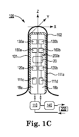
Referring to Fig. 1C, in yet another example embodiment of the present
invention,
there may be one or more separate by operatively coupled inner housing
segments
18a and 18b. As particularly illustrated in Figs. 9A and 9B, an adjustor 20
may be
operatively positioned in recesses or bores 22a and 22b extending into each of
the
housing segments 18a and 18b. The adjustor 20 may comprise any type of
mechanism capable of moving housing segments 18a and 18b generally away from
each other, such that the diameter or circumference of apparatus 100 is
expanded or
increased.
In one example embodiment of the invention, adjustor 20 may comprise a motor
having one or more screws associated with each housing segment 18a and 18b.
The
screws may operate concurrently or separately to move housing segments 18a and
18b between the expanded and resting states. In another example embodiment of
the
invention, adjustor 20 may comprise a compressor that utilizes air or a fluid
to move
housing segments 18a and 18b between the expanded and resting states. The
foregoing is for illustrative purposes only and any type of adjustor may be
utilized
and any number of housing segments may also be used.
Housing 101 or each housing segment 18a and 18b may include an oscillator 120
or
13
CA 03084982 2020-06-05
WO 2019/118561
PCT/US2018/065132
120a and 120b, able to oscillate along one, two, or three axes, and an
accelerometer
130 or 130a and 130b able to measure the acceleration along one, two, or three
axes.
Preferably, the accelerometer axis or axes is/are aligned with the oscillator
axis or
axes, for the following reason:
Assume that oscillator 120 or 120a and 120b effects an oscillation of the
apparatus
along an axis x, and that the response is measured along an axis x' forming an
angle a with the x-axis. If a response along the x-axis is B, then the
response along
the x'-axis B' =B=cos a. B' has a maximum for cos a = 1, i.e. with a = 0 and
the x'-
axis parallel with the x-axis. Correspondingly, B' = 0 when the accelerometer
axis
is perpendicular to the oscillation (cos 90 = 0). Thus, by arranging the x-
axis of
accelerometer 130 or 130a and 130b in parallel with the x-axis of oscillator
120 or
120a and 120b we expect the largest possible signal and hence the greatest
sensitivity possible. The same is true along the y- and/or z-axes when
apparatus
100 has more than one axis. Also, the level of crosstalk between the measured
signals is minimized when the axes are perpendicular to each other, e.g. as
shown
with the x, y, z coordinate system of Fig. 1.
From Fig. 1A it can also be seen that oscillator 120 and accelerometer 130 are
offset relative to each other along the longitudinal axis of the apparatus,
i.e. the z-
axis. Strictly speaking, therefore, they have separate axes in the x
direction, e.g. x
and x'. However, this has no significance as long as the axes are parallel to
each
other, cf. the previous section. Hence, for convenience, the x-axes of the
oscillator,
accelerometer and apparatus are referred to as one axis, "the x-axis". The
same
14
CA 03084982 2020-06-05
WO 2019/118561
PCT/US2018/065132
applies for the y- and z-axes.
Fig. 2 illustrates a triaxial accelerometer 130, having its axes x, y, and z
parallel
with the axes x, y, and z of the apparatus shown in Figs. 1A, 1B and 1C. In a
preferred embodiment, the frequencies of the oscillations, and optionally also
the
amplitudes, can be controlled independently of each other along said x, y, and
z
axes. This makes it possible to measure the strength of a muscle or muscle
group
running in parallel with the main axis of the apparatus, the z-axis,
independently
of muscles or muscle groups acting radially on the apparatus along a
combination
of the x- and y-axes of Fig. 1.
In the following, parameters of one, two, or three dimensions are denoted with
boldfaced characters, and the component of a parameter along the x, y, and/or
z
axis is indexed with x, y, and z, respectively. For example, the frequency oi
= (tux,
toy, toz). In some embodiments, the three frequency components may have
different values, and one or two of the components can be zero, i.e. one or
two
oscillators could be eliminated. The same applies for a response or out signal
a
from accelerometer 130 or 130a 130b, calculated results A A, (p.A, and so on.
Components along the x, y, and z axes are measured and calculated
independently
of each other, e.g. as indicated in eqs. (1) to (4).
The oscillator 120 or 120a and 120b can be controlled to vibrate with a
specific
frequency, preferably within the range of 15-120Hz, by a power supply 110.
Alternatively, the oscillator 120 or 120a and 120b can be driven by a battery
111a,
CA 03084982 2020-06-05
WO 2019/118561
PCT/US2018/065132
111c and 111d, shown in Figs. 1A, 1B and 1C.
The output signal from accelerometer 130, 130a and 130b can be passed to a
signal
processor 140 and thence to a computer 200 (see Figs. 5 and 6). Alternatively,
the
entire or parts of the signal and data processing can be performed by a unit
200a
inside the housing 101.
Oscillator 120, 120a and 120b, accelerometer 130, 130a and 130b, and signal
processor 140 are commercially available products, and it is within the
ability of a
person skilled in the art to select models suited for the particular purpose.
It is
understood that Figs. 1A, 1B and 1C are principle drawings, and that the
connections between the components may include several channels, e.g. one
input
channel per oscillator axis and one output channel per accelerometer axis. In
some
applications, accelerometer 130, 130a and 130b and/or signal processor 140 may
be driven by electric power supplied through a USB connection, for example. In
other applications, it may be necessary or convenient to have a separate grid-
connected transformer 111 in the power supply 110, as shown in Fig. 6.
Fig. 3 illustrates the principle of a possible oscillator 120, 120a and 120b.
The
oscillator shown includes a permanent magnet 126 arranged in a coil 125. When
an
AC voltage Vx is applied to the poles and a current is driven through the
coil, a
variable magnetic field is induced which drives the permanent magnet 126 back
and
forth in a reciprocating motion. The permanent magnet 126 is attached to a
weight
122 which hence also moves back and forth. When the oscillator is attached to
16
CA 03084982 2020-06-05
WO 2019/118561
PCT/US2018/065132
housing 101, the apparatus 100 will oscillate along the x-axis.
Fig. 4 illustrates the principle of a typical accelerometer. A piezoelectric
disc or bar
133 is fixedly clamped within a housing 131. The disc 133 retains a seismic
mass
132. When the housing is moved back and forth along the x-axis, the disc will
be
acted on by the mass 132 and an electric charge is produced, typically a few
pC/g, on
the disc 133 by the piezoelectric effect. For frequencies below about one
third of the
resonance frequency of the accelerometer housing, this charge will be
proportional
with the acceleration. The output signal is illustrated schematically as ax in
Fig. 4.
Commercial vibrational testing accelerometers of this type typically have a
frequency range from approx. 0.1 to above 4kHz, i.e. far outside the range of
15-
120Hz preferred in the present invention.
The present invention does not rely on any specific types of oscillators or
accelerometers. For example, eccentric weight oscillators may be used instead
of
the type shown schematically in Fig. 3. A design of the type shown in Fig. 3
can
also be used as an accelerometer: In such a case, weight 122 is moved in
dependency of the applied forces. This induces a movement of permanent magnet
126 inside coil 125, and a current is induced that can be read at the poles at
Vx=
Fig. 5 illustrates a system in which a computer 200 controls an oscillator of
apparatus 100 through a power supply 110. The computer 200 can be of any
design.
Suitable computers have a programmable processor, and include personal
computers, portable units (PDAs), etc. Computer 200 can be connected to a
display,
17
CA 03084982 2020-06-05
WO 2019/118561
PCT/US2018/065132
printer, and/or data storage in a known manner for displaying and/or logging
measurement results.
Signals from an accelerometer (130 or 130a and 130b, Figs. 1A, 1B or 1C) of
apparatus 100 are amplified and/or processed in a signal processor 140, and
transferred to computer 200 for analysis and/or logging. The connection
between
apparatus 100 and the box 110, 140 may include several channels for
controlling
oscillators along several axes independently of each other as well as for
measuring
responses of a uniaxial or multiaxial accelerometer. The same applies for the
connection between box 110, 140 and computer 200. This connection may be a USB
(2.0 or the like) connection, and, in some applications, electric power may be
supplied from the computer through the USB connection.
In some embodiments, signals may be transferred wirelessly (not shown), e.g.
by
way of radio signals, infrared light, or ultrasonic signals.
Figs. 8A-8D show another embodiment of the system, and in particular a more
detailed embodiment of signal processor 110, 140, according to the present
invention, in which the power supply 110 and signal processor 140 can be
embedded into a separate unit or box 110, 140 accommodating at least one
rechargeable or replaceable battery or battery package 113 (Fig. 8D).
Signal processor 140 may also include: a CPU including the appropriate
software;
electronic circuitry programmed with suitable algorithms for managing and
18
CA 03084982 2020-06-05
WO 2019/118561
PCT/US2018/065132
controlling the oscillation frequency and optionally the oscillation
amplitude;
input(s) for at least one EMG sensor (EMG = Electromyography); and input(s)
for
at least one force sensor. A sensor, such as a force sensor, may be used to
measure
the amount of pretensioning is applied to the proximate tissue.
The stand-alone unit or box 110, 140 can include a charge input. Additionally
to the
charge input, or in an alternative embodiment, in which the battery or
batteries or
the battery package 113 is to be replaced or charged at another location, the
stand-
alone unit or box 110, 140 may include a cover 114 which can be opened and
closed, or the casing (housing) of the unit or one half of the unit or box 110
may be
arranged so as to be easily opened and closed (i.e. without the need for using
a
tool).
The wire 115 from apparatus 100 may be permanently connected 115A to the box
110 of signal processor 140, or, alternatively, may be arranged so as to be
pluggable
115B (by means of a plug 115B) into the input port or connector 116 of the
unit 110,
140.
Signal processor 140 may further include a loudspeaker and/or display 118 for
the
instantaneous or immediate biofeedback on muscle activation as observed
through
the dampening of oscillations and/or force read from the apparatus 100 and/or
EMG activity in the muscle acting on apparatus 100. Display 118 may have a
suitable shape adapted for the requirements of functionality and placement. An
19
CA 03084982 2020-06-05
WO 2019/118561
PCT/US2018/065132
octagonal (eight-sided) 118B, six-sided or round 118A LCD or LED display 118,
having about 40 segments 119, for example, could be used. The unit 110, 140
may
also include an on/off button 117. In addition, or alternatively, the
electronic
circuitry of signal processor 140 may be configured so as to switch off after
a
predetermined time interval of inactivity, e.g. from one to a few minutes of
no
active use.
Additionally, the stand-alone unit or box 110, 140 may include a CPU device
and/or calibration means including at least one of a CPU device and various
sensor means to allow, among other things, the calibration of a new
apparatus 100 in the system. Unit 110, 140 may also transfer, e.g. wireles
sly,
real-time data to computer 200 of various reasons.
Apparatus 100 may include an integrated triaxial gyro sensor which, together
with
the triaxial accelerometer 130, allows the data or signal processor 140 or
computer
200 to calculate the 3D orientation of the apparatus 100.
Fig. 6 is a schematic depiction of components of the system illustrated in
Fig. 5.
A control module 230, e.g. hardware and software in the computer 200,
determines an oscillator parameter, i.e. frequency and/or amplitude, for
oscillator
120. When the apparatus is being used for the first time, the control module
230
could set the frequency oi to a fixed initial value and then increase the
frequency
in predetermined increments Atli. On subsequent use, control module 230 can
use
CA 03084982 2020-06-05
WO 2019/118561
PCT/US2018/065132
previous results for selecting other initial values and/or frequency
intervals. This
is described in more detail below. The same applies for the amplitude
settings.
Alternatively, oscillator parameters could be determined in a binary search
which
is ended when the values of two consecutively calculated values are closer
than a
predetermined resolution, e.g. Atli x = 5Hz.
Both frequency and amplitude may be adjusted along the x, y, and z axes
independently of each other by means of controller 112. In Fig. 6, controller
112 is
connected to a power source in the form of a transformer 111 connected to the
grid
voltage V1, delivering a power P with the desired current and voltage. As
shown in
Fig. 1, in the alternative, the power source could be a battery 111a located
inside the
housing 101 of the apparatus. For example, the controller 112 may control the
amplitude Ax and frequency cox of the oscillator by controlling the current,
voltage,
and frequency of the signal supplied at the poles Vx of Fig 3, and in a
similar
manner for oscillators oscillating along the y and/or z axes.
The oscillation is imposed on tissue surrounding apparatus 100, and the
response is
measured by accelerometer 130 or 130a and 130b.
Signals from accelerometer 130 or 130a and 130b of apparatus 100 are passed to
a
signal processor 140, which is provided as a separate box including an array
of
accelerometers. Accelerometer 130 or 130a and 130b may include a preamplifier,
and unit 140 may include a pre-amplifier. Other configurations are possible as
well.
The output signal from signal processor 140 is shown as a, and may represent,
for
21
CA 03084982 2020-06-05
WO 2019/118561
PCT/US2018/065132
example, acceleration along the x, y, and/or z axes at a measurement point at
which
the imposed oscillation was on.
A data capturing module 210 process the signal further, and may, for example,
integrate an acceleration to obtain a velocity and once more to obtain a
displacement, measure a phase difference, etc. Said integration of
acceleration,
measurement of phase difference, etc. may be carried out at several locations
in the
signal path using feedback operational amplifiers, firmware, and/or software,
for
example, in a known manner. Note that the signal path of Fig. 6 is exemplary
only.
Output data from the data capturing module 210 are shown schematically as a
measurement point to, R, at which a result R is measured or calculated at an
applied frequency cu. The result R may represent one or more of: acceleration
a,
velocity, displacement, relative amplitude attenuation AA, phase shift,
stress,
strain, and/or dynamic modulus as discussed above. In some applications, the
oscillator amplitude may also be varied. Advantageously, the data capturing
module can store a measurement sequence including a series of measurement
points each representative of an oscillator parameter to or A and a measured
or
calculated result R. As used herein and in the claims, the term "data values"
is
understood to mean any parameter value and/or the components thereof along the
x, y, and/or z axes.
A data bus 205 carries data values between various components and modules of
computer 200. For example, a measurement series with a sequence of
22
CA 03084982 2020-06-05
WO 2019/118561
PCT/US2018/065132
measurement points (on, R;) can be temporarily be stored in a data storage 201
before the measurement series is further processed in an analysis module 220.
In
another embodiment, the measurement points (on, R;) could be passed to
analysis
module 220 at a later point, and the processing results, represented by (cur,
S),
could be stored in data storage 201 and/or displayed on a display means 202.
Analysis module 220 is a module processing one or more measurement series to
characterize the musculature and the development thereof using one or more
parameters deemed suitable.
In a preferred embodiment, a maximum response frequency cur is obtained for
each measurement series. The maximum response frequency cur is the value of
the
imposed frequency for which the measurement parameter selected indicated a
maximum response from the tissue surrounding the apparatus, such as the
maximum amplitude attenuation, minimum amplitude measured, largest dynamic
modulus, etc. This is discussed in more detail below.
In principle, analysis module 220 may calculate any desired group value and/or
carry out statistical analysis of the acquired data, such as statistical
distributions,
mean or expected value, variance, maximum values, and trends in the
development of the measured and calculated results described above, for
example.
In one embodiment, for example, the group value S may represent a subinterval
of
the range of 15-120Hz within which the maximum response frequency or is
23
CA 03084982 2020-06-05
WO 2019/118561
PCT/US2018/065132
located with a given probability. This interval may be calculated as a
confidence
interval from earlier measurement series using known statistical methods, and
is
expected to become smaller as the number of measurement series increases and
the
variance hence reduces. The purpose of calculating such a subinterval is to
avoid
superfluous measurements.
An exemplary trend analysis is the development of the maximum response
frequency tor over a few days or weeks, which may provide information on
training
effect.
Fig. 7 illustrates a method according to the invention.
In block 710, the musculature is imposed a first oscillation represented by
cor. In
practice, this can be accomplished by introducing an apparatus as described
above
into a pelvic floor aperture and supply the oscillator 120 with electric
power. The
oscillation may be imposed along one or more mutually orthogonal axes (x, y,
z). At
the first use, the initial value could be about 15Hz, for example, along each
axis.
After the apparatus has been used one or more times the initial values may
be
based on previous results and analyses.
In block 720, the response ai, from the tissue or musculature is measured by
means of an accelerometer 130, 130a or 130b having axes oriented in parallel
with the oscillator axes x, y, and/or z.
24
CA 03084982 2020-06-05
WO 2019/118561
PCT/US2018/065132
Block 730 illustrates that a result Ri is found from an imposed oscillation on
and
its response a; as measured in a predetermined time interval. The measurement
point (on, Ri) may be part of a measurement series in which i = 1, 2, ... n,
and
each index i represents a separate time interval. Both the imposed frequency
and
the measured or calculated result have distinct values along the oscillator
axes.
Results suitable for characterizing the musculature may be the relative
amplitude
attenuation AA, dynamic modulus k, and/or phase shift (I) between the applied
and measured signals. The values may be measured and/or calculated as set out
above in connection with eqs. (1) to (4), and independently of each other
along
the axis or axes x, y, and/or z. The measurement point (on, Ri) can be stored
or
logged as part of this step.
In block 740 an oscillation frequency for the next measurement point is
calculated,
and in determination block 750 a determination is made whether the measurement
series has been completed.
In a first embodiment of the method, the imposed frequency is incrementally
increased in block 740, for example according to cui,= oi 0 + i= Atli, where
Atu
denotes a desired resolution for the measurement series, such as 1Hz or 5Hz.
In this
case, the loop ends in determination block 750 when the new frequency Awl+ 1
exceeds a predetermined threshold, e.g. 120Hz, along the axis or axes.
In an alternative embodiment of the method, the objective is to find a maximum
response using the smallest number of measurements possible. This may be
CA 03084982 2020-06-05
WO 2019/118561
PCT/US2018/065132
carried out efficiently by way of a binary search. For example, assume that
the
result R from block 730 increases with the response of the musculature to the
imposed oscillations, that a first interval is 15Hz to 120Hz, and that the
desired
resolution is 5Hz along each axis. In this case, the binary search can be
performed by bisecting the interval, rounding the frequency down to the
nearest
integer frequency divisible with the resolution, and compare the results of
block
730 for each of the two frequencies in the upper and lower parts of the
interval,
e.g. R1 at col = 15Hz and R2 at oi2 = 50Hz. If R2 > R1, oi3 is selected as the
center of the interval 50-120Hz in block 740, otherwise oi3 is selected as the
center of the interval 15-50Hz in block 740. Similar bisection of the
intervals is
repeated in this alternative embodiment until determination block 750
indicates
that the next interval is narrower than the desired resolution, e.g. 5Hz along
each axis.
If the responses along the axes are independent of each other, a binary search
in
the interval 15-120Hz with a resolution of 5Hz along each axis will be able to
find
an approximate maximum response frequency using at most 6 measurement
points, whereas a sequential search in the interval 15-120Hz with a resolution
of
5Hz would require 21 measurement points.
If determination block 750 indicates that the measurement series has not been
completed, a new iteration is performed in which block 710 imposes an
oscillation
with a new frequency Acui+ 1, etc. When determination block 750 indicates that
the measurement series has been completed, the process proceeds to block 760.
26
CA 03084982 2020-06-05
WO 2019/118561
PCT/US2018/065132
In block 760 one or more measurement series is analyzed as described for
analysis
module 220 above. In a preferred embodiment, the maximum response frequency
or is calculated for each measurement series. By definition, this is the
frequency at
which the musculature responds most strongly to the imposed oscillation. In
practice, the maximum response frequency can be rounded down to the nearest
integer frequency which is divisible with the resolution, i.e.
co, = Ace) =round(e), 7Ace)), (5) where
co, is the practical value of the maximum response frequency,
co, ' is the theoretical or ideal value of the maximum response
frequency,
Ace) = is the resolution chosen, e.g. 5Hz as in the above example,
and
round() is a function which rounds down to the nearest integer.
Block 770 has been drawn with dashed lines to illustrate that the method may,
but
does not necessarily, include controlling the oscillator to impose the
practical value
for the maximum response frequency while a user performs pelvic floor
exercises
as described in the introductory section. Hence, in a preferred embodiment,
the
resolution AU) should be selected so that the difference between the practical
and
actual values is of little or no significance. For example, if it turns out to
be a telling
difference between training with an imposed oscillation of 62Hz as compared to
60Hz, AU) in the above example should be reduced from 5Hz to 1Hz.
27
CA 03084982 2020-06-05
WO 2019/118561
PCT/US2018/065132
The method may further include storing and/or displaying one or more
oscillation
parameters, measurement values, calculated results, and/or group values. Each
data
value may be stored in a data storage 201 and displayed on a monitor 202. It
is also
possible to log parameters by printing them on paper. Hence, a printer (not
shown)
may optionally be used instead of or in addition to data storage 201 and
display 202
(e.g. a monitor) shown in fig. 6.
The method described above may further include analyzing the measured and
calculated results using known statistical methods. In one embodiment, the
development of the maximum response frequency and/or other results over time,
for example, may document the training effect. Also, in the present or other
applications, a confidence interval for tor can be estimated which is smaller
than the
entire measurement interval, e.g. 15-120Hz, but still large enough for the
probability p that the maximum response frequency is located within said
interval
to be larger than a predetermined value, such as p> 95%.
This may reduce the number of measurement points in the next measurement
series,
which may be recorded one or a few days later, for example, and stored in data
storage 201 (Fig. 6). Data storage 201 may store several such measurement
series
recorded during a time period, e.g. one measurement series per day for 1-4
weeks,
and/or only the particular frequency tor within each measurement series which
resulted in, for example, the maximum amplitude attenuation or phase shift.
Naturally, statistical analysis, trend analysis, etc. may be performed on one
or
28
CA 03084982 2020-06-05
WO 2019/118561
PCT/US2018/065132
more measured or calculated results, not only on the frequency as described
above. The expression "calculating group value", as used in the patent claims,
is
intended to include any known types of statistic analysis, trend analysis as
well as
other forms of analysis performed on one or more measured or calculated
results,
stored, for example, as measurement series of measurement points (on, Ri;) in
data
storage 201.
During use, it is not uncommon to encounter a patient with tissue or muscle
that
lacks a preferred amount of tension. For instance, after a woman gives birth
it is
not uncommon for her vaginal tissue to exhibit less viscoelasticity. In these
cases,
it may be beneficial to pre-tension the tissue or muscle prior to applying
mechanotransduction therapy.
In the embodiments of the invention discussed above, a user or practitioner
may
insert apparatus 100 into the patient's vaginal opening. Apparatus 100 may be
operated to cause outer casing 102 to expand. In other embodiments, adjuster
20
may be operated to cause housing segments 18a and 18b to move from the resting
state toward the expanded state. The outer casing 102 or housing segments 18a
and 18b can be adjusted until a desired amount of pre-tension is applied to
the
tissue.
With the tissue or muscle in the pre-tension state, mechanotransduction
therapy
(described above) may be applied to the tissue or muscle. The pre-tensioning
permits the therapy to be more effectively transmitted through the tissue
cells to
create a tissue regenerative environment.
29
CA 03084982 2020-06-05
WO 2019/118561
PCT/US2018/065132
As the patient continues therapy, her tissue or muscle will begin to become
more
viscoelastic and the amount of pre-tensioning may be reduced accordingly.
The above should not be considered to be limited to the treatment of vaginal
incontinence but may be used for the treatment of any tissue, muscle or organ.
For instance, it is within the spirit and scope of the invention to include an
apparatus that is capable of being applied to a patient's chest for
mechanotransduction therapy of the chest tissue, muscles, lungs or heart.
In yet another embodiment of the invention, apparatus 100 may be reduced in
size
such that it may be insertable into a patient to apply mechanotransduction
therapy
proximately or directly to an internal tissue, muscle or organ. For instance,
it is
possible to have an apparatus small enough to be inserted through a
peripherally
inserted central venous catheter to apply therapy directly to the heart.
In still another embodiment of the present invention, as illustrated in Figs.
1D and
1E, pre-tensioning of a patient's tissue may be accomplished by inserting
housing
101 into a sleeve 30 that may be used to expand all or a portion of the
circumference of the housing 101. The sleeve 30 may have a constant or varying
thickness and may vary to accommodate a patient's anatomy. The sleeve 30 may
have an opening 31 disposed on an end for receiving the housing 101. The
sleeve
may have an open or closed end opposite the opening 31.
25 Referring to Fig. 1E, the sleeve 30 may comprise one or more rings 32a,
32b and
CA 03084982 2020-06-05
WO 2019/118561
PCT/US2018/065132
32c. The rings 32a-32c may be connected or separate and may be placed in any
desirable location on housing 101. The rings 32a-32c may have any shape
conducive to targeting particular anatomical features. For instance, the rings
32a-
32c may have a generally curved, ribbed, or undulating outer surface. Other
configurations are also possible and should be considered to be within the
scope of
the present invention.
The sleeve 30 and rings 32a-32c may be manufactured from a material that is
capable of transmitting the mechanotransduction vibrations to the tissue of
the
patient. In one embodiment, the sleeve 30 or the rings 32a-32c may be
manufactured from a pliable material like silicone and the like or a rigid or
semi-
rigid material such as any known or unknown polymer.
In another embodiment of the invention, the pre-tensioning of the tissue may
be
accomplished by activating one or more electrodes or stimulators 34 coupled to
or
mounted in/on housing 101, sleeve 30 or rings 32a-32c. The stimulators 34 can
emit electrical stimuli that causes the proximate tissue to contract.
The
contraction of the tissue may be accomplished by a number of mechanisms,
including causing the stiffening of tissue substrate. Once the proximate
tissue is
stimulated and pre-tensioned the mechanotransduction therapy may be applied,
which results in improved vibrations being transmitted through the tissue. The
stimulators 34 may be in operative communication with a power source disposed
in or external to the housing 101.
The stimulators 34 may also be applied to the embodiment used for application
of
31
CA 03084982 2020-06-05
WO 2019/118561
PCT/US2018/065132
internal mechanotransduction therapy.
Various figures and descriptions disclose features and accessories. However,
it
must be noted that these features are merely illustrative in nature and may be
placed in varying locations and under varying configurations and shapes, and
still
be consistent with the present invention. In addition, the shape and
configuration
for the various portions are also merely illustrative and can be altered
without
deviating from the spirit and scope of the present invention.
In another embodiment of the invention, the disclosed mechanotransduction
therapy is combined with stem cells to treat various medical conditions. In
this
embodiment, stem cells may be introduced into a location of a patient by use
of a
needle and syringe and then the mechanotransduction therapy disclosed herein
may be applied to stimulate the stem cells to differentiate into parts of the
cell.
The present invention may be embodied in other specific forms without
departing
from the spirit or essential attributes thereof, and it is, therefore, desired
that the
present embodiment be considered in all respects as illustrative and not
restrictive. Similarly, the above-described methods and techniques for forming
the present invention are illustrative processes and are not intended to limit
the
methods of manufacturing/forming the present invention to those specifically
defined herein.
32