Note : Les descriptions sont présentées dans la langue officielle dans laquelle elles ont été soumises.
EFFICIENT, SECURE, AND SAFE SYSTEM AND METHOD FOR STORING AND
MONITORING DATA USED FOR REFILLING COMPRESSED-GAS TANKS
Field of the Invention
[0001] The invention relates generally to re-fillable compressed-gas
tanks, and
more particularly to a system and method for storing and monitoring data used
to refill
compressed-gas tanks.
Background of the Invention
[0002] Tanks that store compressed gas are used in a variety of
commercial,
industrial, recreational, governmental, healthcare, and firefighting and other
rescue/safety applications and environments. In almost all cases, the tanks
are
refillable and reusable over the course of their useful life. Regardless of
the type of
tank and the gas it is intended to store, compressed-gas tanks are subject to
a
variety of regulations governing tank identification, use, safety, and record
keeping.
[0003] Traditionally, the filling or refilling of reusable compressed-
gas tanks, as
well as the data/record keeping associated therewith, was a manual operation
prone
to operator error as well as being inherently dangerous to a refilling
operator. More
recently, "radio frequency identification" (RFID) tags have been affixed to
tanks to
help identify important information related to the tank, e.g., the tank's
identification,
purpose, owner, minimum/maximum fill pressures, tank filling parameters,
operating
1
Date Recue/Date Received 2022-03-29
pressures, type of gas the tank is designed to store, storage environment
information/regulations, tank test and/or certification dates, tank end-of-
life date, etc.
Typically, the RFID tag is read prior to some type of manual or automated
filling
operation. The information read from the RFID tag is used to improve the
efficiency
and safety associated with the filling operation.
[0004] In terms of compressed-gas tank filling operations, conventional
RFID
tag reading operations introduce efficiency problems and can introduce safety
concerns. With respect to efficiency, RFID tag reading relies on proper manual
movement/positioning of a manually-manipulated RFID reader, or a properly
positioned fixed-location RFID reader. At a minimum, improper RFID reader
positioning leads to delays in a tank refilling operation. To combat this
issue, higher-
power RFID readers (e.g., on the order of 2 watts or more) are relied upon to
reduce
the reader's sensitivity to reader-to-tag positioning. Unfortunately, the use
of higher-
power RFID readers introduces potential safety issues.
[0005] In terms of safety, it is relevant that most compressed-gas tank-
filling
operations involve the presence of numerous tanks in an environment equipped
to
perform the tank filling operations. In these multi-tank environments, when
operators
rely on higher-power RFID readers (e.g., on the order of 2 watts or more) to
reduce
RFID positioning concerns relative to an RFID tag as described above,
crosstalk
between nearby RFID tags can cause incorrect tag-to-tank associations that are
subsequently relied upon by a filling operator or an automated filling
machine. When
this type of error occurs in either a manual or automated tank filling
operation, the
2
Date Recue/Date Received 2022-03-29
results can be disastrous as a refilling operator/machine relies on the
information it
receives from its reader to institute a tank filling operation. That is, an
incorrect tag-
to-tank association can cause a tank to be over or under pressurized, can
cause an
out-of-certification tank to be filled, etc. Furthermore, higher-power RFID
readers can
generate error warnings when operated near electrically-conductive structures.
At a
minimum, the generation of such error warnings affects the efficiency of a
tank filling
operation.
[0006] In terms of record keeping, RFID tag-based systems rely on the
storage
of tank-related data on the tank's RFID tag as mentioned above. That is, each
tank's
RFID tag stores "static" data (e.g., tank serial number, tank manufactured
date, tank
end-of-life date, etc.) as well as "dynamic" data (e.g., last fill date, last
maintenance
date, current tank owner, etc.) that is updated or changed by an RFID
read/write
device as needed. However, reliance on RFID tag-storage for record keeping
presents a number of problems. For example, many compressed-gas tanks are
subject to harsh environments (e.g., SCBA cylinders used in underwater or fire
environments) and/or rough handling that can damage or destroy an RFID tag.
Furthermore, the use of higher power RFID read/write devices can be the source
of
the aforementioned crosstalk issues resulting in erroneous data reads from (or
writes
to) the wrong RFID tag.
Summary of the Invention
[0007] Accordingly, it is an object of the present invention to provide
a method
3
Date Recue/Date Received 2022-03-29
and system that efficiently, securely, and safely monitors data used in the
refilling of
compressed-gas tanks.
[0008] Other objects and advantages of the present invention will become
more
obvious hereinafter in the specification and drawings.
[0009] In accordance with the present invention, a tank data storing and
monitoring system and method have an RFID tag coupled to and associated with a
tank. The RFID tag has a unique identity specified by a unique identifier
stored
electronically on the RFID tag. Also included are a computer adapted to access
the
internet and a database adapted to be accessible via the internet. The
database stores
data unique to the tank having the RFID tag coupled thereto. An RFID reader
coupled
to the computer is used to read only the unique identifier of the RFID tag.
The
computer accesses the data unique to the tank stored on the database using the
unique
identifier. In an additional aspect of the invention, a unique tank support
system can be
used to hold/support the tank during the RFID tag reading process. In yet
another
aspect of the invention, the RFID tag can be disposed within a unique tag
holder to
properly position the RFID tag's antenna for the RFID tag reading process.
Brief Description of the Drawings
[0010] Other objects, features and advantages of the present invention
will
become apparent upon reference to the following description of the preferred
embodiments and to the drawings, wherein corresponding reference characters
indicate corresponding parts throughout the several views of the drawings and
wherein:
4
Date Recue/Date Received 2022-03-29
[0011] FIG. 1 is a schematic view of a data storing and monitoring
system for
re-fillable compressed-gas tanks in accordance with an embodiment of the
present
invention;
[0012] FIG. 2 is an isolated schematic view of an RFID antenna system
for use
in a compressed-gas tank filling system in accordance with an embodiment of
the
present invention;
[0013] FIG. 3 is a schematic plan view of an RFID antenna system with an
RFID tag disposed within the loop region defined within the system's loop
antenna;
[0014] FIG. 4 is a cross-sectional view of the loop antenna and RFID tag
taken
along line 4-4 in FIG. 3 illustrating the antenna's reading field lines;
[0015] FIG. 5 is a perspective view of the top portion of a compressed-
gas
tank illustrating a perspective view of an RFID tag positioner in accordance
with an
embodiment of the present invention;
[0016] FIG. 6 is an isolated cross-sectional view of the RFID tag holder
in
accordance with an embodiment of the present invention;
[0017] FIG. 7 is a part side and part schematic view of an RFID-based
tank
support system for a compressed-gas tank filling system in accordance with an
embodiment of the present invention;
[0018] FIG. 8 is an enlarged cross-sectional view of a portion of the
tank
container and antenna taken along line 8-8 in FIG. 7;
[0019] FIG. 9 is a cross-sectional view of a portion of a tank container
illustrating the relationship between the container's loop antenna and an RFID
tag
Date Recue/Date Received 2022-03-29
positioner attached to a compressed-gas tank in accordance with an embodiment
of
the present invention;
[0020] FIG. 10 is a part side and part schematic view of a multiple-
container
RFID-based tank support system in accordance with another embodiment of the
present invention; and
[0021] FIG. 11 is a side view of a compressed-gas tank filling machine
illustrating the tank support system incorporated into a door of the tank
filling
machine.
Detailed Description of the Invention
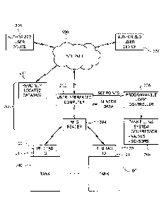
[0022] Referring now to the drawings and more particularly to FIG. 1, a
data
storing and monitoring system for re-fillable compressed-gas tanks in
accordance
with an embodiment of the present invention is shown and is referenced
generally by
numeral 200. In the illustrated embodiment and as will be explained further
below,
system 200 includes tank-filling controls and elements used to fill/re-fill
one or more
compressed-gas tanks 100 such as SCBA cylinders. Each tank 100 has its own
uniquely-identifiable RFID tag 20 coupled thereto. RFID tag 20 can be
attached/installed to tank 100 by the tank manufacturer, or can be coupled to
tank
100 using, for example, a unique holder (not shown in FIG. 1) that improves
readability of RFID tag 20 as will be described later herein in an exemplary
embodiment. As is known in the art, RFID tag 20 has a unique identifier ("ID")
21
stored electronically thereon and has readable/writable memory (not shown). ID
21
6
Date Recue/Date Received 2022-03-29
uniquely identifies RFID tag 20, but is unrelated to any use or purpose with
which
RFID tag 20 will be associated. To achieve the efficiency, safety and security
provided by the present invention, only ID 21 is read from RFID tag 20. That
is,
system 200 does not read any data that is or might be stored on the memory
portion
of RFID tag 20. Further, system 200 does not write any data to RFID tag 20.
Accordingly, in one embodiment of the present invention, the only data
electronically
stored on RFID tag 20 is ID 21.
[0023] System 200 includes a user-interfaced computer 202 (e.g., desktop
computer, laptop computer, tablet-based computer, etc.), an RFID reader 204, a
programmable logic controller 206, a tank filling system 208, and a remotely-
located
database storage/memory 210 (hereinafter referred to as "database 210").
Computer
202 is the user-accessed interface to the tank monitoring functions provided
by the
present invention as well as (in the illustrated embodiment) the tank filling
functions.
As would be understood in the art, computer 202 will include user input
devices (e.g.,
keyboard, mouse, microphone for voice recognition control, etc.), display
and/or
printing devices for data input/output review, internet connectivity devices
(e.g.,
ethernet, wireless transceiver, etc.) for communication over the internet 500,
and
processing and storage devices needed to carry out its functions. The
particular
devices and/or their configurations are not limitations of the present
invention.
[0024] RFID reader 204 is the device that will be used to read ID 21
associated with an RFID tag 20. For example, RFID reader 204 can be a handheld
device that reads RFID tag 20 on a free-standing tank 100, and then
communicates
7
Date Recue/Date Received 2022-03-29
with computer 202 over a hard-wire or wireless connection to transmit the
corresponding ID 21 to computer 202. RFID reader 204 can also be realized by a
unique RFID antenna system that can be included as part of tank filling system
208
as will be explained later herein. Still further, system 200 could include
both a
handheld reader and the above-referenced unique RFID antenna system without
departing from the scope of the present invention.
[0025] Programmable logic controller ("PLC") 206 can be realized by a
variety
of PLCs capable of controlling operation of a number of tank filling
components (e.g.,
compressor(s), valves, sensors used to monitor a gas filling operation, etc.)
based on
set points received from computer 202. PLC 206 returns sensor data, monitored
during a tank filling process, to computer 202.
[0026] Tank filling system 208 includes a number of hardware
elements/systems that cooperate to fill a tank 100 with gas (e.g., a
breathable gas)
as controlled by computer 202 and PLC 206. For example, tank filling system
208
can include dome loading features to control the pressure of the gas during a
tank
filling operation. Briefly, dome loading is realized by the use of a
proportional
pneumatic controller (not shown) that is controlled by PLC 206 to provide a
variable
pneumatic signal to a fill control regulator (not shown). The dome-loaded fill
control
regulator's outlet pressure is thereby increased in proportion to the air
pressure of the
control air received from the proportional pneumatic controller.
[0027] All tank-related data (i.e., both static and dynamic data) is
stored on
database 210 that is accessed by computer 202 via internet 500 where each
tank's
8
Date Recue/Date Received 2022-03-29
data is referenced/indexed to the unique RFID tag ID 21 associated therewith.
In this
way, tank-related data is available in real-time to the user of computer 202
as well as
any user of an authorized-user device 220 capable of accessing internet 500.
Still
further, if an organization employs multiple systems 200 at multiple
locations, all such
systems 200 have access to the same tank data in real-time. Accordingly, an
organization can monitor/fill any of its tanks 100 from any of its systems
200.
[0028] Since system 200 only read's a tank's ID 21, tank monitoring and
filling
efficiency is improved by the very limited amount of data processing required
of RFID
reader 204 and computer 202. Further, since system 200 does not rely on a
tank's
RFID tag for tank data reads or writes, no pertinent tank data is ever at risk
of loss
due to RFID tag damage and no pertinent tank data is ever at risk of an
erroneous
read due to, for example, crosstalk in multi-tank environments. Still further,
using the
present invention, if a tank's RFID tag is ever damaged or otherwise
compromised, a
new RFID tag can be attached/installed on the tank and then associated with
the
existing cloud-based data without the need for any tank-data recovery.
[0029] As mentioned above, RFID reader 204 can be realized by a unique
RFID antenna system that can be included as part of tank filling system 208.
Details
of the RFID antenna system are described in detail in U.S. patent application
number
15/619,746, published as US 2018-0134203 Al on May 17, 2018, and are included
below to provide a complete understanding of the present invention and the
advantages thereof.
[0030] Referring now to FIG. 2, an RFID antenna system that can be used
for
9
Date Recue/Date Received 2022-03-29
the above-described RFID reader 204 for use in compressed-gas tank filling
system
208 is shown and is referenced generally by numeral 10. As will be explained
further
below, antenna system 10 can be used to read the ID for a variety of types of
RFID
tags. Furthermore, antenna system 10 assures that only an intended RFID tag is
read and can be a low-power system to eliminate the possibility of crosstalk
from any
other nearby RFID tag.
[0031]
Antenna system 10 includes a loop antenna 12, a tuning circuit 14, and
an RFID reader 16. In general, loop antenna 12 is an electrically-conductive
element
shaped to define a substantially complete loop terminating in antenna feed
points
12A and 12B. The geometric shape traced by loop antenna 12 can be circular,
oval,
rectangular, etc., without departing from the scope of the present invention.
By way
of example and for purpose of using antenna system 10 in compressed-gas tank
filling system 208, loop antenna 12 will be assumed to trace a circular
geometric
shape for reasons that will be explained further below. Tuning circuit 14 is
an
adjustable device that, when coupled to antenna feed points 12A and 12B,
allows the
electrical impedance of loop antenna 12 to be tuned to match that of RFID
reader 16.
RFID reader 16 is electrically coupled to loop antenna 12 for two-way
communication
therewith via tuning circuit 14. RFID reader 16 can be any commercially-
available or
specially-designed RFID tag-reading device without departing from the scope of
the
present invention. Such RFID readers are well understood in the art and will,
therefore, not be described further herein.
Date Recue/Date Received 2022-03-29
[0032] Antenna system 10 avoids or eliminates the above-described
location-
sensitivity, high-power, and crosstalk problems associated with the reading of
RFID
tags in a compressed-gas tank filling environment. To better explain how
antenna
system 10 overcomes these various RFID tag reading problems, reference will
now
be made to FIGs. 3 and 4 where an RFID tag 20 is positioned within the
confines of
loop antenna 12. The cross-sectional geometry of loop antenna 12 can be
circular
as shown in FIG. 4. However, it is to be understood that the cross-sectional
geometry of loop antenna 12 could be other regular or irregular-shaped
geometries
without departing form the scope of the present invention.
[0033] As is known in the art of RFID technology, all RFID tags include
a
planar antenna that is most effectively interrogated or read when the field
lines of a
reading system's antenna are perpendicular to the plane of the planar antenna.
In
the illustrated embodiment, it will be assumed that a planar antenna 22 is
embedded
within a non-electrically-conducting material casing 24 of RFID tag 20 shown
in FIG.
4. In accordance with the present invention, the field lines of loop antenna
12 are
indicated by field lines 120 in FIG. 4 when RFID reader 16 is operated to read
RFID
tag 20. Field lines 120 will be perpendicular or substantially perpendicular
to planar
antenna 22 when RFID tag 20 is positioned such that planar antenna 22 is
either
aligned with the plane 122 defined by antenna loop 12, is parallel to plane
122 but
still within field lines 120, or is canted at a small angle (e.g.,
approximately 15
degrees or less) relative to plane 122 but still within field lines 120.
11
Date Recue/Date Received 2022-03-29
[0034] When the above-described RFID antenna system and RFID tag are to
be incorporated into compressed-gas tank filling system 208, the present
invention
can include a novel positioning holder to hold RFID tag 20 in a
position/orientation
that assures the above-described relationship between the loop antenna's field
lines
and the RFID tag's planar antenna. For example and with reference to FIG. 5
where
the top portion of a compressed-gas tank 100 (e.g., a SCBA cylinder) is
illustrated, an
RFID tag positioner 30 is coupled to tank 100 at its valve fixture 102, the
design of
which is not a limitation of the present invention. Briefly, tag positioner 30
includes
an attaching collar 32 coupled to tank 100, a locking bracket 34 coupled to
collar 32,
and an RFID tag supporting holder 36 coupled to locking bracket 34 (e.g., via
a
screw attachment thereto. Collar 32 can include an adjustable-length strap 32A
passively or actively tightened about valve fixture 102 by, for example, a
screw clamp
32B.
[0035] Additional and simultaneous reference will now be made to FIG. 6
where supporting holder 36 is shown in an isolated cross-sectional view
thereof.
Supporting holder 36 is made from an electromagnetic (EM) energy transparent
material(s) (e.g., rubber, fiberglass, plastic, wood, cloth, and combinations
thereof).
Supporting holder 36 is configured to support an RFID tag 20 therein. When
supporting holder 36 with RFID tag 20 therein is included in a tag positioner
30
attached to a valve fixture 102 of a tank 100, RFID tag 20 will be placed in
an
orientation that positions the plane of the planar antenna of the RFID tag in
a
perpendicular or near perpendicular orientation relative to the longitudinal
axis 104 of
12
Date Recue/Date Received 2022-03-29
tank 100. More specifically, supporting holder 36 includes a tag housing
region 360
and a tag positioning leg 364. Tag housing region 360 includes a slot 362 that
provides for the insertion of an RFID tag 20 therein such that it is captured
within tag
housing region 360. Once RFID tag 20 has been inserted into slot 362, the
opening
of slot 362 can be sealed. When a tag positioner 30 (inclusive of supporting
holder
36 and RFID tag 20) is attached to valve fixture 102, positioning leg 364
places slot
362 (and the antenna of RFID tag 20 positioned therein) perpendicular (or
nearly
perpendicular) to the tank's longitudinal axis 104 at the crown region of tank
100.
[0036] The above-described antenna system can be included as part of an
RFID-based tank support system for compressed-gas tank filling system 208 as
will
now be described with simultaneous reference to FIGs. 7 and 8. FIG. 7
illustrates an
embodiment of an RFID-based tank support system 50 for a compressed-gas tank
filling machine (not shown), and FIG. 8 is a cross-sectional view of the
system's
container 40 taken along line 8-8 in FIG. 7.
[0037] Tank support system 50 provides mechanical support for a
compressed-gas tank or cylinder (not shown) during a tank filling operation,
while
simultaneously providing for the reading of an RFID tag coupled to the tank.
For
example, the RFID tag could be RFID tag 20 held in place using tag positioner
30 as
described above with reference to FIG. 5. Tank support system 50 includes a
hollow
container 40 having an open (top) end 42 and a closed (bottom) end 44, as well
as
previously-described loop antenna 12, tuning circuit 14, and RFID reader 16.
Container 40 can be a circular cylinder having an inside diameter "D"
sufficient to
13
Date Recue/Date Received 2022-03-29
provide for the loading of a compressed-gas tank. The length or height "H" of
container 40 should be sufficient to substantially or fully contain a
compressed-gas
tank loaded therein.
[0038] Positioned near open top 42 of container 40 is loop antenna 12.
In
general, loop antenna 12 is coupled to the sidewall region of container 40
with its
loop plane perpendicular to the longitudinal axis 46 of container 40. Thus,
for a
container 40 that is a circular cylinder, loop antenna 12 is a circular loop
antenna.
Loop antenna 12 is positioned at a location along the length of container 40
that is
approximately commensurate with the above-described crown region of a
compressed-gas tank when such a tank is in container 40. For example, when the
above-described tag positioner 30 and RFID tag 20 are to be used in
combination for
a particular type of tank that is to be serviced by tank support system 50,
loop
antenna 12 can be positioned along container such that its plane 122 will be
approximately aligned with the portion of a tank at which tag positioner 30
positions a
captured RFIG tag as described above and as illustrated in FIG. 9 where a tank
100
has been placed/positioned in container 40.
[0039] Container 40 can serve as the mechanical support for the
geometric
shape of loop antenna 12. For example, when container 40 is a circular
cylinder,
container 40 can readily provide the mechanical support for a circular
geometric
shape of loop antenna 12. The loop antenna can be an electrically-conductive
wire,
flat strip, etc., mounted on the inside surface of container 40, embedded
fully or
partially within the walls container 40, or mounted on the outside surface of
container
14
Date Recue/Date Received 2022-03-29
40 without departing from the scope of the present invention. For example, in
the
embodiment illustrated in FIG. 8, loop antenna 12 resides in an inward-facing
and
contiguous annular notch 48 defined in the sidewall of container 40 to thereby
support and protect loop antenna 12. Notch 48 lies in a plane 48A that is
perpendicular to longitudinal axis 46 of container 40 to thereby assure
perpendicularity between plane 122 of loop antenna 12 and longitudinal axis
104 of a
tank 100 that is to be placed in container 40 as illustrated in FIG. 9.
[0040] Tuning circuit 14 is electrically coupled to loop antenna 12 and
can be
mounted on container 40 to facilitate its usage. Another advantage of mounting
tuning circuit 14 on container 40 is that tank support system 50 can be
readily and
accurately tuned in a factory environment thereby allowing it to function as a
"plug in"
module of a compressed-gas tank filling machine. RFID reader 16 can be mounted
on container 40 or located near container 40 without departing from the scope
of the
present invention. Container 40 can be made completely of one or more non-
magnetic, non-electrically-conducting material(s) to prevent any interference
with the
reading field of loop antenna 12. At a minimum, container 40 should exhibit
non-
magnetic and non-conducting properties in the vicinity of the reading field of
loop
antenna 12. For example, suitable materials for container 40 include, but are
not
limited to, rubber, fiberglass, plastic, wood, cloth, and combinations
thereof.
[0041] Tank support system 50 employing the loop antenna-based RFID tag
reading system as described herein reduces the power requirements needed to
accurately read an RFID tag on a compressed-gas tank positioned in the
system's
Date Recue/Date Received 2022-03-29
container 40. Typical power output of the RFID reader need only be on the
order of 1
watt or less. At such low power levels, tank support system 50 will not be
subject to
crosstalk interference from any other nearby RFID tags not in container 40.
Furthermore, the low-power and no crosstalk features and advantages of tank
support system 50 make it an ideal candidate for clustering in a multiple
container
tank filling machine. For example and with reference to FIG. 10, a multiple-
container
RFID-based tank support system 60 uses a plurality of tank support systems 50
in a
side-by-side arrangement. While three tank support systems 50 are illustrated,
more
or fewer could be used without departing from the scope of the present
invention. All
tank support systems 50 can be coupled to a single RFID reader 16 (as shown),
or
each tank support system 50 could have its own dedicated RFID reader coupled
thereto without departing from the scope of the present invention.
[0042] A single tank support system 50 or multiple-container tank
support
system 60 can be incorporated into an automated compressed-gas tank filling
machine. For example and with reference to FIG. 11, a compressed-gas tank
filling
machine 80 is shown with the tank support system's supporting door open and
indicated by reference numeral 82. Door 82 is coupled to machine 80 by a hinge
84
that allows door 82 to rotate into or out of machine 82 as indicated by two-
headed
arrow 86. It is to be understood that machine 80 includes numerous other
mechanical and electrical elements/systems omitted from FIG. 11 for clarity of
illustration. Mounted on door 82 is one (or more) tank support system 50. Open
top
16
Date Recue/Date Received 2022-03-29
42 of container 40 can be angled as shown to facilitate the insertion/removal
of a
compressed-gas tank and/or the opening/closing of door 82.
[0043] In use, an operator would load a compressed gas tank into
container 40
and couple the tank filling equipment (not shown) thereto. The tank can have
an
RFID tag positioner (not shown) coupled thereto as described above and as
shown in
FIG. 4. Door 82 could then be rotated towards machine 80 such that containment
system 50 is fully within machine 80. Reading of the RFID tag's ID associated
with a
tank in tank support system 50 can then be commenced and the RFID tag ID can
be
used by machine 80 to access tank-related data stored on database 210 (FIG. 1)
as
described earlier herein. The tank-related data read/retrieved only from
database
210 is then used by computer 202 to issue set points to PLC 206 in order to
carry out
the tank-filling operation by tank filling system 208.
[0044] The advantages of the present invention are numerous. The
compressed-gas data storing and monitoring system is ideally suited to be
incorporated with a tank filling system to provide tank-related data that is
used and/or
updated for efficient, safe, and secure tank filling and re-filling
operations. Only the
tank's associated RFID tag ID need be read thereby simplifing processing and
recovery in the event of RFID tag destruction or failure. All tank-related
data is
readily available across a variety of platforms to include multiple
monitoring/filling
stations utilized by the same organization thereby allowing any station to
service any
tank efficiently, safely, and securely at any of the organization's stations.
17
Date Recue/Date Received 2022-03-29
[0045] The present invention can use the tank support system
incorporating
tank identification as described herein to accurately read just the intended
RFID tag's
ID coupled to a gas tank in the tank support system. The system's ability to
use a
low-power RFID reader allows multiple tank support systems to be clustered
together
without any crosstalk concerns. Furthermore, since the system's antenna is
sensitive
to RFID tags that only lie within the confines of the antenna's loop and since
the
antenna can operate at low power levels on the order of 1 watt, the antenna is
not
affected by nearby electrically-conductive structures located outside of the
antenna
loop's perimeter. Use of the tag positioner described herein on a tank further
assures
optimum RFID tag placement for efficient and accurate reading of an RFID tag.
Thus, the tank support system described herein is an ideal candidate for
incorporation into a compressed-gas tank filling machine that typically
includes a
large amount of electrically-conductive structural materials. For all of the
above
reasons, the invention described herein will greatly improve the efficiency
and safety
of compressed-gas tank filling operations.
[0046] Although the invention has been described relative to specific
embodiments thereof, there are numerous variations and modifications that will
be
readily apparent to those skilled in the art in light of the above teachings.
It is therefore
to be understood that, within the scope of the appended claims, the invention
may be
practiced other than as specifically described.
18
Date Recue/Date Received 2022-03-29