Note : Les descriptions sont présentées dans la langue officielle dans laquelle elles ont été soumises.
CA 03085595 2020-06-11
WO 2019/136280 PCT/US2019/012390
SYSTEM AND METHOD FOR STICK-SLIP VIBRATION MITIGATION
CROSS-REFERENCE TO RELATED APPLICATION
[0001] This application claims the benefit of U.S. Provisional Application
Ser. No. 62/613,986,
filed January 5, 2018, which is incorporated herein by reference in its
entirety.
BACKGROUND
1. Field of the Invention.
[0002] The present inventive concept relates to a system and method to
mitigate vibration of a
drill-string during a drilling process. In particular, the present inventive
concept concerns a
system operable to obtain data regarding stick-slip vibration of the drill-
string during the drilling
process, and process the data to mitigate the stick-slip vibration, and a
method of using the
system.
2. Description of Related Art.
[0003] A drill-string of a drilling rig can exhibit a variety of vibrations
during use that may
damage the drill-string and/or the drilling rig. One particular type of
vibration, known as stick-
slip vibration, occurs when a drill bit at a bottom of the drill-string is
rotating at a different angular
speed than a top drive motor at the top of the drill-string, which is
typically caused by friction in
the wellbore. When stick-slip vibration occurs, portions of the drill-string
can completely stick to
the formation, while the upper portion of the drill-string continues to
rotate. When a portion of
the drill-string that is stuck overcomes the static friction of the formation,
the drill-string will
suddenly speed up and release the stored energy, which can damage the drill
bit, the drill-string,
and/or the drilling rig, thereby increasing drilling costs.
[0004] Conventional systems attempt to reduce stick-slip vibration by reducing
the lowest
frequency of the stick-slip vibration. This conventional approach is
ineffective when a higher
frequency exhibits a stronger or comparable energy level than the lowest
frequency, which is a
common scenario. In such a scenario, while the lower frequency of the
vibration is reduced, the
higher frequency remains strong, which results in continued stick-slip
vibration.
[0005] Accordingly, there is a need for an improved system and method to
mitigate stick-slip
vibration.
- 1 -
CA 03085595 2020-06-11
WO 2019/136280 PCT/US2019/012390
SUM MARY
[0006] The present inventive concept provides a system and method for stick-
slip vibration
mitigation. The system generally includes a sensor, a processor, a non-
transitory storage
medium, and a controller. The system is operable to be used with a drill-
string in a wellbore to
obtain stick-slip vibration data of the drill-string and calculate a
controller setting based on the
stick-slip vibration data to mitigate the stick-slip vibration. The method
provides steps to reduce
the stick-slip vibration using the system. The system of the present inventive
concept
advantageously mitigates stick-slip vibration by targeting and reducing
multiple vibration modes
of the stick-slip vibration during the drilling process, thereby improving
efficiency of the drilling
process.
[0007] The aforementioned may be achieved in an aspect of the present
inventive concept by
providing a system configured to mitigate vibration in a drill-string. The
system may include a
sensor configured to measure a torque of the drill-string. The sensor may be
configured to yield
measurement data. The system may further include a processor configured to
determine a
plurality of vibration modes using the measurement data. The process may be
configured to
determine a frequency and an amplitude of each the plurality of vibration
modes. The processor
may be configured to determine a controller setting via minimization of an
objective function
based on a reflectivity of vibrations energy at the plurality of vibration
modes. The controller
setting may be configured to reduce at least one of the plurality of vibration
modes, preferably a
plurality of the plurality of vibration modes, and most preferably all of the
plurality of vibration
modes. The system may further include a controller configured to control the
drill-string based
on the controller setting to mitigate the plurality of vibration modes. The
system may further
include a non-transitory storage medium configured to store program logic for
execution by the
processor. The processor may be configured to execute the program logic to
determine an
optimization of the controller setting based on the frequency and the
amplitude of each of the
plurality of vibration modes, wherein the optimization includes reducing the
reflectivity of
vibrations energy at one of the plurality of vibration modes and limiting a
dampening of another
of the plurality of vibration modes. Using the program logic, the processor
may be configured to
obtain a reflectivity of torsional waves at a top drive of the drill-string.
Using the program logic,
the processor may be configured to obtain the objective function as a weighted
sum of
reflectivity at each frequency plus a width of an absorption band. Using the
program logic, the
processor may be configured to solve the optimization numerically by applying
a numerical
- 2 -
CA 03085595 2020-06-11
WO 2019/136280 PCT/US2019/012390
minimization method and yielding a PI D control. Using the program logic, the
processor may be
configured to determine an RPM command based on the PID control. Using the
program logic,
the processor may be configured to calculate the RPM command in a time domain.
Using the
program logic, the processor may be configured to calculate the RPM command in
a frequency
domain. The non-transitory storage medium may be configured to store a delay
program logic
for execution by the processor. The processor may be configured to execute the
delay program
logic to determine the optimization of the controller setting based on the
frequency and the
amplitude of each of the plurality of vibration modes. Using the delay program
logic, the
processor may be configured to determine a time delay by comparing the
controller setting to an
actual controller setting by determining a cross-correlation between a first
signal of the controller
setting and a second signal of the actual controller setting in a moving
window. Using the delay
program logic, the processor may be configured to select a time lag
corresponding to a
maximum of the cross-correlation as the time delay. Using the delay program
logic, the
processor may be configured to convert the time delay to a phase shift. Using
the delay
program logic, the processor may be configured to apply the phase shift to the
first signal to
offset the effect of the delay. Using the delay program logic, the processor
may be configured
to calculate the phase shift. The controller may be configured to apply the
phase shift to a
spectra of the controller setting.
[0008] The aforementioned may be achieved in another aspect of the present
inventive concept
by providing a method to mitigate vibration in a drill-string. The method may
include the step of
measuring, via a sensor, a drill-string torque to yield measurement data. The
method may
further include the step of determining, via a processor, a plurality of
vibration modes using the
measurement data. The step of determining the plurality of vibration modes via
the processor
may include performing a spectral analysis on the measurement data. The step
of processing
the measurement data may use a Maximum Entropy method to determine a spectral
content of
the measurement data during the spectral analysis. The method may further
include the step of
determining, via the processor, the frequency and the amplitude of each of the
plurality of
vibration modes. The method may further include the step of determining, via
the processor, a
controller setting via a minimization of an objective function based on a
reflectivity of vibration
energy of the plurality of vibration modes. The step of determining the
controller setting may
include performing an optimization of the measurement data based on the
frequency and the
amplitude of each of the plurality of vibration modes, wherein the
optimization may include (i)
- 3 -
CA 03085595 2020-06-11
WO 2019/136280 PCT/US2019/012390
reducing the reflectivity of vibration energy at one of the plurality of
vibration modes, and (ii)
limiting a dampening of another of the plurality of vibration modes. The
optimization may be
performed by calculating a reflectivity of torsional waves at a top drive of
the drill-string. The
optimization may be performed by obtaining the objective function as a
weighted sum of
reflectivity at each frequency plus a width of an absorption band. The
optimization may include
solving the optimization numerically by applying a numerical minimization
method to yield a PID
control. The numerical minimization method may be a quasi-Newton scheme. The
method may
further include the step of controlling, via a controller, the drill-string
based on the controller
setting to mitigate the plurality of vibration modes. The controller setting
may be configured to
reduce at least one of the plurality of vibration modes, preferably a
plurality of the plurality of
vibration modes, and most preferably all of the plurality of vibration modes.
The method may
further include the step of determining, via the processor, an RPM command
based on the PID
control. The step of determining the RPM command may include calculating, via
the processor,
the RPM command in a time domain. The step of determining the RPM command may
include
the step of calculating, via the processor, the RPM command in a frequency
domain. The
method may further include the step of applying, via the processor, a delay
program logic to the
controller setting. The delay program logic may include the step of
determining, via the
processor, a time delay by comparing the controller setting to an actual
controller setting by
determining a cross-correlation between a first signal of the controller
setting and a second
signal of the actual controller setting in a moving window. The delay program
logic may further
include the step of selecting, via the processor, a time lag corresponding to
a maximum of the
cross-correlation as the time delay. The delay program logic may further
include the step of
converting, via the processor, the time delay to a phase shift. The delay
program logic may
further include the step of applying, via the controller, the phase shift to
the first signal to offset
the effect of the delay. The phase shift may be calculated via the processor.
The phase shift
may be applied, via the controller, to a spectra of the controller setting.
[0009] The aforementioned may be achieved in another aspect of the present
inventive concept
by providing a method to mitigate vibration in a drill-string. The method may
include the step of
measuring, via a sensor, torque of a drill-string to yield measurement data.
The method may
further include the step of performing, via a processor, a spectral analysis
of the measurement
data to yield a spectral content. The method may further include the step of
determining, via the
processor, a plurality of vibration modes using the spectral content. Each of
the plurality of
- 4 -
CA 03085595 2020-06-11
WO 2019/136280 PCT/US2019/012390
vibration modes may have a frequency and an amplitude. The method may further
include the
step of determining, via the processor, an objective function as a weighted
sum of reflectivity at
each frequency of the plurality of vibration modes plus a width of an
absorption band. The
method may further include the step of determining, via the processor, a
controller setting via a
minimization of the objective function. The method may further include the
step of applying, via
the processor, a delay program logic to the controller setting if a time delay
is identified between
the controller setting and an actual controller setting. The method may
further include the step
of controlling, via a controller, a top drive based on the controller setting
to mitigate the plurality
of vibration modes.
[0010] The aforementioned may be achieved in another aspect of the present
inventive concept
by providing a system configured to mitigate vibration in a drill-string. The
system may include a
sensor configured to measure torque of a drill-string and/or yield measurement
data. The
system may include a processor configured via program logic to perform a
spectral analysis of
the measurement data to yield a spectral content. The processor may be further
configured via
the program logic to determine a plurality of vibration modes using the
spectral content. Each of
the plurality of vibration modes may have a frequency and an amplitude. The
processor may be
further configured via the program logic to determine an objective function as
a weighted sum of
reflectivity at each frequency of the plurality of vibration modes plus a
width of an absorption
band. The processor may be further configured via the program logic to
determine a controller
setting via a minimization of the objective function. The processor may be
further configured via
the program logic to apply delay program logic to the controller setting if a
time delay is
associated with the controller setting. The system may include a non-
transitory storage medium
configured to store the program logic and the delay program logic. The system
may include a
controller configured to control the drill-string, e.g., a top drive of the
drill-string, based on the
controller setting to mitigate the plurality of vibration modes.
[0011] The aforementioned may be achieved in another aspect of the present
inventive concept
by providing a method to determine a plurality of frequencies of a drill-
string. The method may
include the step of measuring, via a sensor, a drill-string torque of a drill-
string to yield
measurement data. The method may further include the step of determining, via
a processor, a
plurality of vibration modes using the measurement data. The method may
further include the
step of determining, via the processor, a frequency and an amplitude of each
of the plurality of
vibration modes.
- 5 -
CA 03085595 2020-06-11
WO 2019/136280 PCT/US2019/012390
[0012] The aforementioned may be achieved in another aspect of the present
inventive concept
by providing a method to optimize measurement data of a drill-string. The
method may include
the step of measuring, via a sensor, a drill-string torque of a drill-string
to yield measurement
data. The method may further include the step of determining, via a processor,
a plurality of
vibration modes of the drill-string using the measurement data. The method may
include the
step of determining, via a processor, a plurality of vibration modes of a
drill-string. The method
may further include the step of determining, via the processor, a controller
setting via a
minimization of an objective function based on a reflectivity of vibration
energy of the plurality of
vibration modes. The method may further include the step of determining, via
the processor,
the controller setting via an optimization of the measurement data based on
the frequency and
the amplitude of each of the plurality of vibration modes.
[0013] The aforementioned may be achieved in another aspect of the present
inventive concept
by providing a method to control a top drive of a drill-string. The method may
include the step of
determining, via a processor, a plurality of vibration modes of a drill-
string. The method may
further include the step of determining, via the processor, a controller
setting via a minimization
of an objective function based on a reflectivity of vibration energy of the
plurality of vibration
modes. The method may further include the step of controlling, via a
controller, the drill-string
based on the controller setting to mitigate the plurality of vibration modes.
[0014] The aforementioned may be achieved in another aspect of the present
inventive concept
by providing a method to mitigate vibration in a drill-string. The method may
include the step of
measuring, via a sensor, a drill-string torque of a drill-string to yield
measurement data. The
method may further include the step of determining, via a processor, a
plurality of vibration
modes using the measurement data. The method may further include the step of
determining,
via the processor, a frequency and an amplitude of each of the plurality of
vibration modes. The
method may further include the step of determining, via the processor, a
controller setting via a
minimization of an objective function based on a reflectivity of vibration
energy of the plurality of
vibration modes. The method may further include the step of determining, via
the processor,
the controller setting via an optimization of the measurement data based on
the frequency and
the amplitude of each of the plurality of vibration modes. The method may
further include the
step of controlling, via a controller, the drill-string based on the
controller setting to mitigate the
plurality of vibration modes.
- 6 -
CA 03085595 2020-06-11
WO 2019/136280 PCT/US2019/012390
[0015] The aforementioned may be achieved in another aspect of the present
inventive concept
by providing a system configured to determine a plurality of frequencies of a
drill-string. The
system may include a sensor configured to measure a drill-string torque of a
drill-string to yield
measurement data. The system may further include a processor configured to
determine a
plurality of vibration modes using the measurement data. The system may
further include the
processor configured to determine a frequency and an amplitude of each of the
plurality of
vibration modes.
[0016] The aforementioned may be achieved in another aspect of the present
inventive concept
by providing a system configured to optimize measurement data of a drill-
string. The system
may include a sensor configured to measure a drill-string torque of a drill-
string to yield
measurement data. The system may further include a processor configured to
determine a
plurality of vibration modes of the drill-string using the measurement data.
The processor may
further be configured to determine a controller setting via a minimization of
an objective function
based on a reflectivity of vibration energy of the plurality of vibration
modes. The processor may
further be configured to determine the controller setting via an optimization
of the measurement
data based on the frequency and the amplitude of each of the plurality of
vibration modes.
[0017] The aforementioned may be achieved in another aspect of the present
inventive concept
by providing a system operable to control a top drive of a drill-string. The
system may include a
processor configured to determine a plurality of vibration modes of a drill-
string. The processor
may be further configured to determine a controller setting via a minimization
of an objective
function based on a reflectivity of vibration energy of the plurality of
vibration modes. The
system may further include a controller configured to control the top drive of
the drill-string
based on the controller setting to mitigate the plurality of vibration modes.
[0018] The aforementioned may be achieved in another aspect of the present
inventive concept
by providing a system configured to mitigate vibration in a drill-string. The
system may include a
sensor configured to measure a drill-string torque of a drill-string to yield
measurement data.
The system may further include a processor configured to determine a plurality
of vibration
modes using the measurement data. The processor may be further configured to
determine a
frequency and an amplitude of each of the plurality of vibration modes. The
processor may be
further configured to determine a controller setting via a minimization of an
objective function
based on a reflectivity of vibration energy of the plurality of vibration
modes. The processor may
- 7 -
CA 03085595 2020-06-11
WO 2019/136280 PCT/US2019/012390
be further configured to determine a controller setting via a minimization of
an objective function
based on a reflectivity of vibration energy of the plurality of vibration
modes. The system may
further include a controller configured to control the top drive of the drill-
string based on the
controller setting to mitigate the plurality of vibration modes.
[0019] The foregoing is intended to be illustrative and is not meant in a
limiting sense. Many
features of the embodiments may be employed with or without reference to other
features of
any of the embodiments. Additional aspects, advantages, and/or utilities of
the present
inventive concept will be set forth in part in the description that follows
and, in part, will be
apparent from the description, or may be learned by practice of the present
inventive concept.
BRIEF DESCRIPTION OF THE DRAWINGS
[0020] The foregoing summary, as well as the following detailed description,
will be better
understood when read in conjunction with the appended drawings. For the
purpose of
illustration, there is shown in the drawings certain embodiments of the
present disclosure. It
should be understood, however, that the present inventive concept is not
limited to the precise
embodiments and features shown. The accompanying drawings, which are
incorporated in and
constitute a part of this specification, illustrate an implementation of
apparatuses consistent with
the present inventive concept and, together with the description, serve to
explain advantages
and principles consistent with the present inventive concept.
[0021] FIG. 1 is a diagram illustrating a stick-slip vibration mitigation
system of the present
inventive concept with a drilling rig, a drill-string sensor, and supporting
facilities in use with a
wellbore and drill-string;
[0022] FIG. 2 is a diagram of the supporting facilities of FIG. 1 having a
computing device and a
controller;
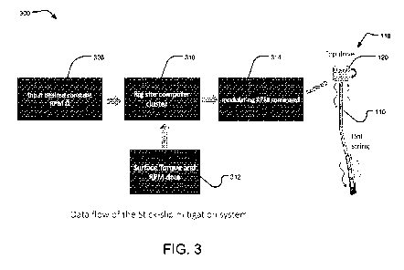
[0023] FIG. 3 is a diagram of a data flow of the stick-slip vibration
mitigation system, illustrated
in FIG. 1, to a top drive of the drilling rig;
[0024] FIG. 4 is a graph illustrating a reflectivity profile when a
fundamental mode is stronger
than a first higher mode;
[0025] FIG. 5 is a graph illustrating the reflectivity profile when the first
higher mode is stronger
than the fundamental mode;
- 8 -
CA 03085595 2020-06-11
WO 2019/136280 PCT/US2019/012390
[0026] FIG. 6 is a graph illustrating the reflectivity profile when the
fundamental mode and the
first higher mode are similar;
[0027] FIG. 7 is a graph of a frequency dependent phase shift;
[0028] FIG. 8A is a graph illustrating weight-on-bit and torque of a field
test;
[0029] FIG. 8B is a graph illustrating an RPM command and an actual RPM of the
field test; and
[0030] FIG. 80 is a graph illustrating a predicted RPM of a bottom hole
assembly and an actual
RPM of the bottom hole assembly of the field test.
DETAILED DESCRIPTION
[0031] The following detailed description references the accompanying drawing
that illustrates
various embodiments of the present inventive concept. The illustration and
description are
intended to describe aspects and embodiments of the present inventive concept
in sufficient
detail to enable those skilled in the art to practice the present inventive
concept. Other
components can be utilized and changes can be made without departing from the
scope of the
present inventive concept. The following detailed description is, therefore,
not to be taken in a
limiting sense. The scope of the present inventive concept is defined only by
the appended
claims, along with the full scope of equivalents to which such claims are
entitled.
I. TERMINOLOGY
[0032] The phraseology and terminology employed herein are for the purpose of
description
and should not be regarded as limiting. For example, the use of a singular
term, such as, "a" is
not intended as limiting of the number of items. Also, the use of relational
terms such as, but
not limited to, "top," "bottom," "left," "right," "upper," "lower," "down,"
"up," and "side," are used in
the description for clarity in specific reference to the figures and are not
intended to limit the
scope of the present inventive concept or the appended claims. Further, it
should be
understood that any one of the features of the present inventive concept may
be used
separately or in combination with other features. Other systems, methods,
features, and
advantages of the present inventive concept will be, or become, apparent to
one with skill in the
art upon examination of the figures and the detailed description. It is
intended that all such
additional systems, methods, features, and advantages be included within this
description, be
- 9 -
CA 03085595 2020-06-11
WO 2019/136280 PCT/US2019/012390
within the scope of the present inventive concept, and be protected by the
accompanying
claims.
[0033] The present disclosure is described below with reference to operational
illustrations of
methods and devices. It is understood that each operational illustration and
combination of
operational illustrations can be implemented by means of analog or digital
hardware and
computer program instructions. The computer program instructions can be
provided to a
processor of a general purpose computer, special purpose computer, ASIC, or
other
programmable data processing apparatus, such that the instructions, which
execute via the
processor of the computer or other programmable data processing apparatus,
implement the
functions/acts specified in the operational illustrations or diagrams.
[0034] Further, it is understood that the specific order or hierarchy of steps
in the methods
disclosed are instances of example approaches. Based upon design preferences,
it is
understood that the specific order or hierarchy of steps in the method can be
rearranged while
remaining within the disclosed subject matter. The accompanying method claims
present
elements of various steps in a sample order, and are not necessarily meant to
be limited to the
specific order or hierarchy presented.
[0035] For the purposes of this disclosure, "program logic" refers to computer
program code
and/or instructions in the form of one or more software modules, such as
executable code in the
form of an executable application, an application programming interface (API),
a subroutine, a
function, a procedure, an applet, a servlet, a routine, source code, object
code, a shared
library/dynamic load library, or one or more instructions. These software
modules may be
stored in any type of a suitable non-transitory storage medium, or transitory
storage medium,
e.g., electrical, optical, acoustical, or other form of propagated signals
such as carrier waves,
infrared signals, or digital signals.
[0036] For the purposes of this disclosure, a non-transitory storage medium or
computer
readable medium (or computer-readable storage medium/media) stores computer
data, which
data can include program logic (or computer-executable instructions) that is
executable by a
computer, in machine readable form. By way of example, a computer readable
medium may
comprise computer readable storage media, for tangible or fixed storage of
data, or
communication media for transient interpretation of code-containing signals.
Computer
readable storage media, as used herein, refers to physical or tangible storage
(as opposed to
- 10-
CA 03085595 2020-06-11
WO 2019/136280 PCT/US2019/012390
signals) and includes without limitation volatile and non-volatile, removable
and non-removable
media implemented in any method or technology for the tangible storage of
information such as
computer-readable instructions, data structures, program modules or other
data. Computer
readable storage media includes, but is not limited to, RAM, ROM, EPROM,
EEPROM, flash
memory or other solid state memory technology, CD-ROM, DVD, or other optical
storage,
magnetic cassettes, magnetic tape, magnetic disk storage or other magnetic
storage devices, or
any other physical or material medium which can be used to tangibly store the
desired
information or data or instructions and which can be accessed by a computer or
processor.
[0037] For purposes of this disclosure, a "wireless network" should be
understood to couple
devices with a network. A wireless network may employ stand-alone ad-hoc
networks, mesh
networks, Wireless LAN (WLAN) networks, cellular networks, or the like. A
wireless network
may further include a system of terminals, gateways, routers, or the like
coupled by wireless
radio links, or the like, which may move freely, randomly or organize
themselves arbitrarily, such
that network topology may change, at times even rapidly. A wireless network
may further
employ a plurality of network access technologies, including Long Term
Evolution (LTE), WLAN,
Wireless Router (WR) mesh, or 2nd, 3rd, or 4th generation (2G, 3G, or 4G)
cellular technology,
or the like. Network access technologies may enable wide area coverage for
devices, such as
client devices with varying degrees of mobility, for example.
[0038] For example, a network may enable RF or wireless type communication via
one or more
network access technologies, such as Global System for Mobile communication
(GSM),
Universal Mobile Telecommunications System (UMTS), General Packet Radio
Services
(GPRS), Enhanced Data GSM Environment (EDGE), 3GPP Long Term Evolution (LTE),
LTE
Advanced, Wideband Code Division Multiple Access (WCDMA), North American/CEPT
frequencies, radio frequencies, single sideband, radiotelegraphy,
radioteletype (RTTY),
Bluetooth, 802.11b/g/n, or the like. A wireless network may include virtually
any type of wireless
communication mechanism by which signals may be communicated between devices,
such as
a client device or a computing device, between or within a network, or the
like.
[0039] Further, as the present inventive concept is susceptible to embodiments
of many
different forms, it is intended that the present disclosure be considered as
an example of the
principles of the present inventive concept and not intended to limit the
present inventive
concept to the specific embodiments shown and described. Any one of the
features of the
present inventive concept may be used separately or in combination with any
other feature.
- 11 -
CA 03085595 2020-06-11
WO 2019/136280 PCT/US2019/012390
References to the terms "embodiment," "embodiments," and/or the like in the
description mean
that the feature and/or features being referred to are included in, at least,
one aspect of the
description. Separate references to the terms "embodiment," "embodiments,"
and/or the like in
the description do not necessarily refer to the same embodiment and are also
not mutually
exclusive unless so stated and/or except as will be readily apparent to those
skilled in the art
from the description. For example, a feature, structure, process, step,
action, or the like
described in one embodiment may also be included in other embodiments, but is
not
necessarily included. Thus, the present inventive concept may include a
variety of combinations
and/or integrations of the embodiments described herein. Additionally, all
aspects of the
present disclosure, as described herein, are not essential for its practice.
Likewise, other
systems, methods, features, and advantages of the present inventive concept
will be, or
become, apparent to one with skill in the art upon examination of the figures
and the description.
It is intended that all such additional systems, methods, features, and
advantages be included
within this description, be within the scope of the present inventive concept,
and be
encompassed by the claims.
[0040] Lastly, the terms "or" and "and/or," as used herein, are to be
interpreted as inclusive or
meaning any one or any combination. Therefore, "A, B or C" or "A, B and/or C"
mean any of the
following: "A," "B," "C"; "A and B"; "A and C"; "B and C"; "A, B and C." An
exception to this
definition will occur only when a combination of elements, functions, steps or
acts are in some
way inherently mutually exclusive.
II. GENERAL ARCHITECTURE
[0041] Turning to FIGS. 1-3, a stick-slip vibration mitigation system 100 of
the present inventive
concept is illustrated in use with a drilling rig 118 having a top drive motor
120 at a surface of a
wellbore 108. The drilling rig 118 includes a drill-string 110 extending into
the wellbore 108 with
a drill-string sensor 102 and supporting facilities 104 positioned at a top of
the wellbore 108. The
wellbore 108 extends into the ground and is formed via a drilling process
using the drill-string
110. A depth of the wellbore 108 can range from a few feet to over a mile into
the ground and
can extend in one or more directions. The drill-string 110 includes a drill
pipe and a bottom hole
assembly (BHA) 112 positioned at a bottom of the drill-string 110. The BHA 112
includes a
plurality of components. In the exemplary embodiment, the BHA 112 includes a
steering unit, a
mud motor, a drill motor, a drill collar, and a drill bit 106. It is foreseen
that the BHA 112 may
include fewer or additional components without deviating from the scope of the
present
- 12 -
CA 03085595 2020-06-11
WO 2019/136280 PCT/US2019/012390
inventive concept. The drill-string 110 extends into the wellbore 108 so that
the bit 106 of the
BHA 112 is in contact with a geological formation to crush and/or scrape the
geological
formation, thereby increasing a length of the wellbore 108 in a downward
direction and/or a
lateral direction. In the exemplary embodiment, the bit 106 is driven by the
top drive 120 and/or
the mud motor positioned near the bit 106.
[0042] A drilling mud or a drilling fluid 114 is continuously circulated
within the wellbore 108 via
a pump to facilitate operation of the BHA 112, e.g., drilling. The fluid 114
is introduced into the
drill-string 110 via an opening of the drill-string 110 and pumped down the
drill-string 110 and
through the BHA 112 via the pump. The fluid 114 exits the drill-string 110
through the bit 106
and circulates upwards through an annulus of the wellbore 108. The fluid 114
has multiple
functions including, but not limited to, cooling the bit 106, lubricating the
bit 106, and/or
transporting debris generated by the bit 106 away from the bit 106, e.g., up
the annulus of the
wellbore 108 and to the surface of the wellbore 108. The fluid 114 may be
water, oil, a synthetic
based composition, gas, or a combination thereof, and may include one or more
additives
and/or particles.
[0043] The drill-string sensor 102 is configured to measure a torque of the
drill-string 110 and
yield measurement data of the drill-string torque. It is foreseen that the
drill-string sensor 102
may be configured to measure acceleration and speed without deviating from the
scope of the
present inventive concept. It is foreseen that the drill-string sensor 102 may
be, or include, a
strain gauge, accelerometer, gyroscope, and/or seismometer without deviating
from the scope
of the present inventive concept. It is foreseen that the torque may be
measured as a high-
fidelity measurement.
[0044] In the exemplary embodiment, the drill-string sensor 102 is positioned
at or adjacent to
the top of the drill-string 110, but it is foreseen that the drill-string
sensor 102 can be positioned
along any portion of the drill-string 110 without deviating from the scope of
the present inventive
concept. For instance, it is foreseen that the drill-string sensor 102 can be
positioned on the
BHA 112 or in a sub positioned under the top drive 120 without deviating from
the scope of the
present inventive concept.
[0045] The supporting facilities 104 include a controller 206 and a computing
device 208. The
computing device 208 includes a processor 202 and a non-transitory storage
medium 204. In
the exemplary embodiment, the measurement data is transmitted from the drill-
string sensor
- 13-
CA 03085595 2020-06-11
WO 2019/136280 PCT/US2019/012390
102 to the non-transitory storage medium 204 via a wireless connection of a
wireless network,
although it is foreseen that the measurement data can be transmitted to the
non-transitory
storage medium 204 via a wired connection without deviating from the scope of
the present
inventive concept. The non-transitory storage medium 204 tangibly stores the
measurement
data for processing by the processor 202.
[0046] The processor 202 is configured to process the measurement data by
executing
program logic, which is also stored by the non-transitory storage medium 204.
Using the
program logic, the processor 202 is configured to determine at least one
vibration mode using
the measurement data. In the exemplary embodiment, the at least one vibration
mode is a
plurality of vibration modes, but it is foreseen that the at least one
vibration mode can be a
single vibration mode without deviating from the scope of the present
inventive concept.
[0047] Using the program logic, the processor 202 is also configured to
determine a frequency
and an amplitude of each of the plurality of vibration modes. Using the
program logic, the
processor 202 is also configured to determine a controller setting that is
effective to reduce at
least one of the plurality of vibration modes via minimization of an objective
function based on a
total reflectivity of vibration energy at all of the plurality of vibration
modes and a width of an
absorption band. In the exemplary embodiment, the controller setting is
effective to reduce at
least one of the plurality of vibration modes, preferably a plurality of the
plurality of vibration
modes, and most preferably all of the plurality of vibration modes.
[0048] The controller 206 is configured to receive the controller setting from
the processor 202,
and modify one or more drilling parameters of the drill-string 110 via the top
drive 120. In this
manner, application of the controller setting via the drill-string 110 is
effective to reduce stick-slip
vibration. Regarding the one or more drilling parameters, in the exemplary
embodiment, the
controller setting is converted to a rotations-per-minute (RPM) command 314,
via the processor
202, which is effective to cause the top drive 120 to rotate the drill-string
110 at a speed
measured in RPMs. By adjusting the RPM of the top drive 120 using the RPM
command 314,
the stick-slip vibration can be mitigated, i.e., at least reduced and
preferably eliminated from the
drill-string 110, via the system 100.
[0049] FIG. 3 illustrates a data flow 300 of the system 100. A desired RPM
input 308 is entered
into the computing device 208 by a user of the system 100 and stored in the
non-transitory
storage medium 204. The measurement data of the drill-string 110 torque from
the drill-string
- 14 -
CA 03085595 2020-06-11
WO 2019/136280 PCT/US2019/012390
sensor 102 and/or RPM data 312 are received by the non-transitory storage
medium 204 of the
computing device 208. The RPM data 312 is the RPM measured by the drill-string
sensor 102
at the top drive 120. The processor 202 of the computing device 208 calculates
the RPM
command 314 based on the desired RPM input 308, and the measurement data and
the RPM
data 312. The RPM command 314 is transmitted from the computing device 208 to
the
controller 206. The controller 206 controls the top drive 120 via a wireless
connection of the
wireless network. It is foreseen that the RPM command 314 can be transmitted
to the top drive
120 or otherwise controlled by the controller 206 via a wired connection
without deviating from
the scope of the present inventive concept.
[0050] With reference to FIGS. 1-3, a method of using the system 100 to
mitigate stick-slip
vibration is as follows. The method includes the step of measuring, via the
drill-string sensor
102, the drill-string torque to yield the measurement data. The method of
using the system 100
further includes the step of determining, via the processor 202, the at least
one vibration mode
using the measurement data. The measurement data is measured in real-time via
the drill-
string sensor 102 and transmitted to the processor 202 in real-time. In the
exemplary
embodiment, the measurement data is measured and transmitted at a high
sampling rate that is
decimated to a sampling rate, but it is foreseen the measurement data may be
measured and
transmitted in other forms without deviating from the scope of the present
inventive concept.
[0051] During the step of determining the at least one vibration mode, the
measurement data is
partitioned into overlapping moving windows, wherein the span of the moving
windows is longer
than a longest period of interest. The step of determining the at least one
vibration mode further
includes performing, via the processor 202, a spectral analysis on the
measurement data. The
spectral analysis uses a Maximum Entropy method, which is used for short time
series with
discrete frequency content, to determine a spectral content of the measurement
data. It is
foreseen that other methods may be used in the spectral analysis such as, but
not limited to a
Fourier Transform, without deviating from the scope of the present inventive
concept. The
spectrum content corresponds to a most random time series whose
autocorrelation agrees with
the measurement data. The spectral analysis advantageously enables the system
100 to
identify a plurality of frequencies of a plurality of amplitudes in real-time.
In an exemplary
embodiment, the system 100 is configured to identify up to three frequencies,
but it is foreseen
that the system 100 may be configured to identify any number of frequencies,
e.g., only one
- 15-
CA 03085595 2020-06-11
WO 2019/136280 PCT/US2019/012390
frequency or more than three frequencies, without deviating from the scope of
the present
inventive concept.
[0052] The method of using the system 100 further includes the step of
determining, via the
processor 202, the frequency and the amplitude of the at least one vibration
mode. In the
exemplary embodiment, the at least one vibration mode includes the plurality
of vibration
modes. It is foreseen, however, that the system 100 may be utilized with only
one vibration
mode without deviating from the scope of the present inventive concept. The
method of using
the system 100 further includes the step of determining, via the processor
202, the frequency
and the amplitude of each of the plurality of vibration modes. The frequency
and the amplitude
of the plurality of vibration modes are stored in the non-transitory storage
medium 204.
[0053] By measuring the frequency and the amplitude of each of the plurality
of vibration
modes, rather than only measuring a fundamental vibration mode, e.g., the
lowest frequency,
the system 100 is advantageously able to determine the vibration mode which is
causing the
most damage to the system 100, e.g., the drill-string 110, BHA 112, and/or bit
106.
Furthermore, by measuring the plurality of vibration modes via the system 100,
the vibration
mode most likely causing the most damage to the system 100 can be more easily
identified and
mitigated. Also, in addition to mitigating the vibration mode at a highest
energy, additional
vibration modes which may be causing damage can also be reduced using the
system 100.
[0054] The method of using the system 100 further includes the step of
determining, via the
processor 202, the controller setting 206 via the minimization of the
objective function based on
the reflectivity of vibration energy of the at least one vibration mode.
The controller setting is
configured to reduce at least one of the plurality of vibration modes,
preferably a plurality of the
plurality of vibration modes, and most preferably all of the plurality of
vibration modes.
[0055] The step of determining the controller setting further includes
performing an optimization
of the measurement data based on the frequency and the amplitude of the at
least one vibration
mode. The optimization is effective to reduce the reflectivity of vibration
energy at the at least
one vibration mode. The optimization is further effective to limit a dampening
of another
vibration mode of the plurality of vibration modes. The optimization is
performed by calculating,
via the processor 202, a reflectivity of torsional waves at or adjacent to the
top drive 120 of the
drill-string 110, as sensed by the drill-string sensor 102, where the
reflectivity of torsional waves
is the equation:
- 16 -
CA 03085595 2020-06-11
WO 2019/136280
PCT/US2019/012390
IR (6)) I = ((z - !I) - i(ao -1)160))10 i(a)D - (1)
wherein w is an angular frequency of the reflectivity of torsional waves, z is
the
impedance of the drill pipe of the drill-string, i is an imaginary unit
defined by its property i2= -1,
and P, I, and D are a proportional, an integral, and a derivative factor of
the top drive 120,
respectively.
[0056] The optimization is then performed, via the processor 202, by obtaining
the objective
function as a weighted sum of reflectivity at each frequency plus the width of
the absorption
band using the equation:
f = EKA,R,(co ,))1 + (J)E, A, (2)
= =
wherein A_i is a measured amplitude of an i-th mode of the at least one
vibration mode
at a frequency w_i, R_i is the reflectivity, Ow is the half width of the
absorption band calculated
from Equation (1) using Ow= Iw1-w21/2, and A is a scalar constant. As such, if
w_O is a
frequency at which R(w) is at a minimum R_min, w_1 and w_2 are two frequencies
near w_0,
and R(w) is halfway between 1 and R_min, or (1+R_min)/2, then a half distance
between w_1
and w2, or Iw1-w21/2, is the half width of the absorption band, which is a
frequency band where
torsional vibration energy is dampened. The second term in Equation (2)
prevents the system
100 from damping a wide range of frequencies, which would result in the
controller setting being
too soft. The scalar constant A controls the relative weight between the two
terms. It is
foreseen that other implements of the second term can be used to regularize
the weight
between the two terms.
[0057] The method includes the step of solving the optimization numerically,
via the processor
202, by applying a numerical minimization method to Equations (1) and (2) to
yield a PID
control. The numerical minimization method is a quasi-Newton scheme. The PID
control is
further processed through a moving median filter to produce a smooth output.
By calculating
the frequency and performing the optimization, the system 100 advantageously
yields the PID
control based on a dynamic description of the frequency and amplitude of the
at least one
vibration mode.
- 17-
CA 03085595 2020-06-11
WO 2019/136280 PCT/US2019/012390
[0058] FIGS. 4-6 are respective graphs 400, 500, 600 that illustrate various
reflection coefficient
vs. frequency scenarios, wherein a reflectivity profile 406 generated by the
system 100 of the
present inventive concept is illustrated dampening modes at different
strengths, i.e., a
fundamental vibration mode 402 and a first higher vibration mode 404. The
reflection coefficient
vs. frequency graph 400 of FIG. 4 illustrates the reflectivity profile 406
when the fundamental
vibration mode 402 is stronger than the first higher vibration mode 404,
resulting in the
reflectivity profile 406 dampening the fundamental vibration mode 402. The
reflection coefficient
vs. frequency graph 500 of FIG. 5 illustrates the reflectivity profile 406
when the first higher
vibration mode 404 is stronger than the fundamental vibration mode 402,
resulting in the
reflectivity profile 406 dampening the first higher mode 404. The reflection
coefficient vs.
frequency graph 600 of FIG. 6 illustrates the reflectivity profile 406 when
the fundamental
vibration mode 402 and the first higher vibration mode 404 are similar,
resulting in the reflectivity
profile 406 preferentially dampening the fundamental vibration mode 602 while
also partially
dampening the first higher vibration mode 404. As such, the reflectivity
profile 406 is not limited
to only dampening the fundamental vibration mode 402, but is also capable of
dampening the
vibration mode with the highest energy. In this manner, the reflectivity
profile 406 allows the
system 100 to dampen the most damaging vibration mode, e.g., stick-slip
vibration, of the
system 100. Further, the reflectivity profile 406 also allows the system 100
to dampen vibration
modes near the energy level of the vibration mode with the highest energy, as
illustrated by FIG.
6, where both the fundamental vibration mode 402 and the first higher
vibration mode 404 are
dampened.
[0059] The method of using the system 100 further includes the step of
controlling, via the
controller 206, the drill-string 110 based on the controller setting to
mitigate the at least one
vibration mode. The method of using the system 100 further includes the step
of determining,
via the processor 202, the RPM command 314 based on the PI D control. It is
foreseen that the
top drive 120 can be directly controlled by changing the top drive 120 control
PID gains using
the PI D control. The RPM command 314 functions as an effective virtual PI D
control, which can
be periodically transmitted from the controller 206 to the top drive 120
without requiring any
additional access by the user to the top drive 120. For example, to change PI
D gains of the top
drive 120, the RPM command 314 can be entered into an existing control via the
user's existing
access. In this manner, the system 100 is configured to make dynamic, real-
time adjustments
to the top drive 120 using the RPM command 314. Because the system 100 does
not require
- 18-
CA 03085595 2020-06-11
WO 2019/136280
PCT/US2019/012390
additional access to any components, e.g., the top drive 120, the system 100
can be retrofitted
to any drilling rig 118 regardless of top drive 120 or other components, which
may be have
different design configurations or otherwise vary from rig to rig.
[0060] The processor 202 is configured to calculate, via the processor 202,
the RPM command
314 in a time domain and/or a frequency domain. The step of controlling the
drill-string 110
using the controller setting includes calculating, via the processor 202, the
RPM command 314
in the time domain using the equations:
0(1)(0
+ if (10- (40) D ____________________________________
(3)
(t) ow(t)'
= Po(ilt(t) - (40) + 10 f dt(fr(t) (A)(t)) Do ___ at - ____
Equation (3) reduces to a second order differential equation:
Do (62,70Mt2) + P06X/St + 10X = Peo(t) + ijdt e0(t) + D (6eo(t))/8t (4)
wherein P, 1, and D are from Equation (1), P_0, 1_0, and D_O are known default
gains
used by the drilling rig 118, w(t) is a measured surface RPM, (Mt)) is the RPM
command 314,
0- is a user specified RPM set point, e_O (t) = D¨w(t), e_1 (t) = (t)¨w(t),
and X(t) = t dt e_1
(t), and wherein Equation (4) is solved numerically with initial conditions:
X(0) = 0, X'(0) = e_1
(0)=0.
[0061] The step of controlling the drill-string 110 using the controller
setting further includes
calculating, via the processor 202, the RPM command 314 in the frequency
domain using the
equation:
COOT- = (5)
wherein T(f) is a torque signal measured at the top drive 120 and Z_d (f) = -
(P+iwD+I/iw)
and is a frequency dependent impedance of the top drive 120. The torque signal
is transformed
into the frequency domain and converted to the RPM spectra by dividing by
Z_d(F), then
transformed back to the time domain. A constant scalar may also be applied to
the converted
RPM spectra.
- 19-
CA 03085595 2020-06-11
WO 2019/136280
PCT/US2019/012390
[0062] The time domain method calculates the RPM command 314 from the surface
RPM
measurement and requires a high accuracy. Sometimes the RPM measurement is not
sufficiently accurate, as determined by the user, to enable use of the time
domain method. For
example, if a sampling rate of the RPM data 312 is too low, e.g., <10Hz, the
user may
determine the RPM measurement is not sufficiently accurate to enable use of
the time domain
method. The frequency domain method uses the surface torque measurement, and
torque is
typically measured to a higher accuracy than the RPM measurement. As such, the
frequency
domain method may be preferred over the time domain method, in some scenarios,
to calculate
the RPM command 314.
[0063] The method of using the system 100 further includes the step of
applying, via the
processor 202, a delay program logic to the controller setting. A time delay
may exist in the
communication time between the drill-string sensor 102 and the controller 206,
which can be
mitigated by the processor 202 using the delay program logic. By executing the
delay program
logic, the processor 202 is able to continuously compare the RPM command 314
or the PID
command to an actual RPM command or an actual PID command, so that the
processor 202 is
able to identify the time delay, if any. Using the delay program logic, the
processor 202 is
configured to determine a cross-correlation between a first signal of the
controller setting and a
second signal of an actual controller setting in a moving window. Using the
delay program logic,
the processor 202 is further configured to select a time lag corresponding to
a maximum of the
cross-correlation as the time delay. Using the delay program logic, the
processor 202 is further
configured to apply a phase shift to the first signal to offset the time
delay. The phase shift is
calculated, via the processor 202, using the equation:
O(f) = wAt (6)
wherein w is an angular frequency of the phase shift and At is the time delay.
The
phase shift is applied, via the controller 206, by multiplying exp(iwAt) to a
spectra of the
controller setting.
[0064] Turning to FIG. 7, a RPM vs. time graph 700 of a frequency dependent
phase shift is
illustrated having an original signal 702 and a phase shifted signal 704. The
phase shifted
signal 704 is the original signal 702 after a phase shift has been applied to
the original signal
702. It is foreseen that the time delay can be determined by other techniques
without deviating
from the scope of the present inventive concept. For example, the time delay
may be obtained
- 20 -
CA 03085595 2020-06-11
WO 2019/136280 PCT/US2019/012390
by a visual inspection of the controller setting and the actual setting. A
phase shift to offset the
time delay may then be manually created and applied to the controller setting
using the
controller 206 of the system 100.
[0065] Turning to FIGS. 8A-C, results from a field test using the system 100
are illustrated. FIG.
8A is a graph 800 illustrating a weight-on-bit 806 and a torque 808 of the
field test. FIG. 8B is a
graph 802 illustrating the RPM command 314 and an actual RPM 814 of the field
test. FIG. 80
is a graph 804 illustrating a predicted RPM 818 of the BHA 112 and an actual
RPM 816 of the
BHA 112 of the field test. During the field test, the system 100 measured the
weight-on-bit 806,
the torque 808, RPM of the top drive 120, and the RPM of the BHA 112. As
illustrated by FIG.
8A, both the amplitude of the torque 808 and the amplitude of the weight-on-
bit 806 decreased
when the system 100 was activated, thereby resulting in a smooth output. FIG.
8B illustrates a
comparison between the RPM command 314 and the actual RPM 814, with the RPM
command
314 controlling and smoothing the output of the measured RPM. FIG. 80
illustrates a
comparison between the predicted RPM 818 and the actual RPM 816. As
illustrated, the
predicted BHA RPM 818 rapidly matched the measured BHA RPM 816 upon activation
of the
system 100, thereby causing the measured BHA RPM 816 to become smoother.
[0066] In this manner, the system 100 of the present inventive concept
advantageously
mitigates stick-slip vibration by targeting and reducing multiple vibration
modes of the stick-slip
vibration during the drilling process, thereby improving efficiency of the
drilling process.
[0067] It will be appreciated by those skilled in the art that changes could
be made to the
embodiments described above without departing from the broad inventive concept
thereof. It is
understood, therefore, that the present inventive concept disclosed herein is
not limited to the
particular embodiments disclosed, and is intended to cover modifications
within the spirit and
scope of the present inventive concept.
- 21 -