Note : Les descriptions sont présentées dans la langue officielle dans laquelle elles ont été soumises.
CA 03086477 2020-06-19
WO 2019/125408
PCT/US2017/067271
MERCHANDISER INCLUDING CONDUCTIVE COATING TO HEAT FRAME
BACKGROUND
[0001] The present
invention relates to refrigerated merchandisers, and more specifically
to condensation control for refrigerated merchandiser frame elements.
[0002] Existing
refrigerated merchandisers generally include a case defining a product
display area that supports and/or displays products visible and accessible
through an opening
in the front of the case. Some refrigerated merchandisers include doors that
enclose the
product display area of the case. The doors typically include one or more
glass panels that
allow a consumer to view the products stored inside the case. The doors are
supported by a
frame that includes a header, a footer, and a pair of side rails. If the
merchandiser includes
more than one door, mullions can be positioned between the doors, extending
from the header
to the footer.
[0003] Often,
condensed moisture accumulates on one or more surfaces of the
merchandiser, including exterior surfaces of the door and frame. Existing
merchandisers
often include a frame heater that is a wire element positioned inside of the
frame. Typically,
merchandisers include a single, continuous heater that extends inside frame
along the outer
edges and the mullions so that heat is applied to the interior of frame. By
leaving the wire
heating element on for a period of time, heat is conducted through the frame
from the interior
to the exterior, eventually heating the exterior surface and removing or
reducing
condensation. Heating through the frame member to achieve condensation
reduction requires
high power and/or longer heating times.
SUMMARY
[0004] According to
an exemplary embodiment, a refrigerated merchandiser includes a
case defining and separating a product display area from an ambient
environment. A frame is
connected to the case. The frame has a frame member with an interior portion
facing the
product display area and an exterior portion facing the ambient environment. A
coating is
layered on the frame between the exterior portion of the frame member and the
ambient
environment. The coating includes conductive particles. A door is pivotally
connected to the
frame and encloses at least a portion of the product display area. The door
includes a door
frame and a panel coupled to the door frame.
1
86744780
[0005] According to another exemplary embodiment, a refrigerated
merchandiser includes
a case defining and separating a product display area from an ambient
environment. A frame is
connected to the case. The frame has a frame member with an interior portion
facing the product
display area and an exterior portion facing the ambient environment. A coating
is layered on the
frame between the exterior portion of the frame member and the ambient
environment. The
coating includes conductive particles. An electrical connector is in contact
with the coating and
configured to operatively connect to a power supply.
[0006] Another exemplary embodiment relates to a method of reducing
condensation on a
refrigerated merchandiser. A case is provided defining and separating a
product display area
from an ambient environment. A frame is connected to the case and has a frame
member with an
interior portion facing the product display area and an exterior portion
facing the ambient
environment. A coating that includes conductive particles is applied to at
least a portion of the
frame member between the exterior portion and the ambient environment. Power
is provided to
the coating to generate heat and reduce condensation.
[0006a] Another exemplary embodiment relates to a refrigerated
merchandiser comprising:
a case defining a product display area and including a frame; a coating
disposed on the frame and
in communication with the ambient environment, wherein the coating includes
conductive
particles, and wherein the coating has a first coating section with a first
thickness and a second
coating section with a second thickness that is different from the first
thickness, and wherein the
first thickness correlates to a first amount of heat configured to be
generated by the first coating
section and the second thickness correlates to a second amount of heat
configured to be
generated by the second section.
10006b1 Another exemplary embodiment relates to a refrigerated
merchandiser comprising:
a case defining a product display area; a frame connected to the case and
having a frame
member; a coating on the frame member and disposed in one or more channels of
the frame
member, each of the one or more channels having a depth, the coating including
conductive
particles and having a thickness defined by the depth of the one or more
channels; and an
electrical connector in contact with the coating and configured to operatively
connect to a power
supply.
2
Date Recue/Date Received 2022-06-13
86744780
10006c1 Another exemplary embodiment relates to a method of reducing
condensation on a
refrigerated merchandiser comprising: providing a case defining a product
display area, wherein
a frame is connected to the case and has a frame member in communication with
ambient
environment; applying a coating to the frame member, the coating including
conductive particles
and in communication with an ambient environment, the coating having a first
coating section
with a first thickness and a second coating section with a second thickness
that is different from
the first thickness, wherein the first thickness correlates to a first amount
of heat configured to be
generated by the first coating section and the second thickness correlates to
a second amount of
heat configured to be generated by the second section; and providing power to
the coating to
generate heat and reduce condensation.
[0007] Other aspects of the invention will become apparent by
consideration of the
detailed description and accompanying drawings.
BRIEF DESCRIPTION OF THE DRAWINGS
[0008] Fig. 1 is a front perspective view of a refrigerated merchandiser
including a case
and embodying the invention.
[0009] Fig. 2 is a perspective view of a portion of the merchandiser of
claim 1 including a
case frame and doors attached to the case frame.
[0010] Fig. 3 is a schematic cross-section of the refrigerated
merchandiser of Fig. 1.
[0011] Fig. 4 is a perspective view of a bottom frame member of the case
frame including
a bottom rail member, an outer cover, an inner cover, and a conductive coating
applied to
portions of the bottom rail member.
[0012] Fig. 5 is a perspective view of the bottom of rail member of
Fig. 4 without the
conductive coatings.
2a
Date Recue/Date Received 2022-06-13
CA 03086477 2020-06-19
WO 2019/125408
PCT/US2017/067271
[0013] Fig. 6 is perspective view of the bottom rail member and conductive
coating of
Fig. 4.
[0014] Fig, 7 is a side view of Fig. 6 illustrating the lower frame rail
and the conductive
coating.
[0015] Fig. 8 is a perspective view of the electrical connector of Fig. 4.
[0016] Fig, 9 is a side view of the electrical connector of Fig. 8.
[0017] Before any constructions of the invention are explained in detail,
it is to be
understood that the invention is not limited in its application to the details
of construction and
the arrangement of components set forth in the following description or
illustrated in the
following drawings. The invention is capable of other constructions and of
being practiced or
of being carried out in various ways. Also, it is to be understood that the
phraseology and
terminology used herein is for the purpose of description and should not be
regarded as
limiting. The use of "including," "comprising," or -having" and variations
thereof herein is
meant to encompass the items listed thereafter and equivalents thereof as well
as additional
items.
DETAILED DESCRIPTION
[0018] Fig, 1 illustrates an exemplary a refrigerated merchandiser 10 that
may be located
in a supermarket or a convenience store (not shown) for presenting fresh food,
beverages, and
other product 14 to consumers. As shown, the merchandiser 10 includes a case
20 that has a
base 22, a rear wall 24, side walls 26, a canopy 28, and doors 30 that are
coupled to the case
20. The area at least partially enclosed by the base 22, rear wall 24, side
walls 26, and the
canopy 28 defines a product display area 32 that supports the product 14 in
the case 20. The
product 14 is displayed on racks or shelves 34 extending forward from the rear
wall 24, and is
accessible by consumers through the doors 30 positioned adjacent the front of
the case 20.
[0019] With reference to Fig. 2, the case 20 includes a frame 40 that is
located adjacent a
front of the merchandiser 10 and that pivotally supports the doors 30. In an
exemplary
embodiment, the frame 40 has a series of frame members including a top frame
member 42, a
bottom frame member 44, a pair of end mullions 46 (only one shown), and one or
more
center mullions 48. The center mullions 48 define customer access openings 50
and support
3
CA 03086477 2020-06-19
WO 2019/125408
PCT/US2017/067271
the doors 30 adjacent upper and lower extents of the mullions 48 so that the
doors 30 can
move to an open position to expose the openings 50. The openings 50 provide
access to the
product 14 stored in the product display area 32. The mullions 48 are
structural members of
the frame 40 spaced horizontally along the case 20. The frame members can be
made by
extruding metallic or non-metallic material (e.g., aluminum, plastic, carbon
fiber, etc.), or by
other manufacturing methods (e.g., molded, cast, etc.), and can have different
sizes, shapes,
and configurations. Each door 30 includes a panel 52 that has one or more
glass panes so that
product 14 can be viewed through the door 30 from outside the case 20. A
handle 54 is
coupled to each door 30 to facilitate opening and closing the door 30.
[0020] Referring to
Fig. 3, at least a portion of a refrigeration system 60 is in
communication with case 20 to condition the product display area 32 via heat
exchange
relationship between a refrigerant flowing through the refrigeration system 60
and an airflow
(denoted by arrows 62) that is directed toward the product display area 32. In
some
embodiments, the refrigeration system 60 includes an evaporator 64 that is
coupled to the
case 20 within an air passageway 66, a refrigerant driving device (e.g., a
compressor or a
pump - (not shown)), and a heat rejection heat exchanger (not shown). It will
be appreciated
that some components of the refrigeration system 60 (e.g., the driving device,
the heat
rejection heat exchanger such as a condenser or cooler, etc.) can be located
remote from the
merchandiser 10. Components and operation of the refrigeration system 60 are
well known
and will not be discussed in detail.
[0021] The airflow
62 is refrigerated or cooled by heat exchange with refrigerant in the
evaporator 64. The refrigerated airflow 62 is directed into the product
display area 32 through
an air outlet 68 to condition the product display area 32 within a
predetermined temperature
range (e.g., 33-41 degrees Fahrenheit, approximately 32 degrees or below,
etc.). Air is then is
drawn into the air passageway 66 through an air inlet 70 via a fan 72 that is
located upstream
of the evaporator 64. Although the merchandiser 10 is illustrated and
described with one
passageway 66, it will be appreciated that the merchandiser can include two or
more
passageways. Furthermore, the illustrated merchandiser 10 is only exemplary
and the
merchandiser 10 may include other features.
[0022] Because the
product display area 32 is maintained within a temperature range that
is relatively cold when compared to the ambient environment surrounding the
merchandiser,
condensation can form on one or more surfaces of the frame 40, one or more
surfaces of the
4
CA 03086477 2020-06-19
WO 2019/125408
PCT/US2017/067271
glass panel 52, or both, when the temperature of the surface(s) falls below a
threshold dew
point temperature (i.e. based on the relative humidity of the ambient
environment).
Condensation is a result of a combination of surface temperature and moisture
in the
surrounding air. For example, condensation can form on one or more interior or
exterior
surfaces the frame 40 ancUor the glass panel 52 after the door 30 has been
opened due to
exposure of the relatively cold interior case structure to warm ambient
conditions. To remove
condensation, the glass panel 52 can include a heated coating (not shown)
affixed on a
surface of one or more glass panes. The heated coating provides resistance
heating via
electrical power from a power source (not shown) to which the heated coating
is connected.
The heat provided by the heated coating quickly removes or "de-fogs"
condensation formed
when the door 30 is opened.
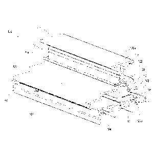
[0023] Figs. 4-7
show one example of a portion of a bottom frame member 100 that
includes a bottom rail 102 with an exterior portion 104 that faces the ambient
environment
and an interior portion 106 that faces the product display 14 area of a
merchandiser 10. The
exterior portion 104 of the bottom rail 102 includes a front edge 108 and a
support surface
110 extending from the front edge 108. When connected to the merchandiser, the
front edge
108 extends substantially perpendicular to the floor and along the width of
the merchandiser,
with the outer surface of the front edge facing the ambient environment.
[0024] A vertical
wall 112 extends substantially perpendicular from the support surface
110. A lower wall 114 extends substantially perpendicular to the vertical wall
112. A
connecting wall 115 extends between the lower wall 114 and an upper wall 116.
The lower
wall 114, connecting wall 115, and the upper wall 116 cooperate to partially
define a gasket
channel 118 that is configured to receive a door gasket (not shown). An outer
cover 120 is
connected to the exterior portion 104 of the bottom rail 102 and an inner
cover 122 is
connected to the interior portion 106 of the bottom rail 102.
[0025] With
continued reference to Figs. 4-7, the bottom frame member 100 includes
conductive coating sections disposed on one or more surfaces of the exterior
portion 104 of
the bottom rail 102. Figs. 4, 6, and 7 show a first conductive coating section
126a disposed
on a portion of the connecting wall 115, and a second conductive coating
section 126b that is
continuous from an upper surface of the lower wall 114 to the support surface
110 such that
the coating section 126b covers a portion of an upper surface of the lower
wall 114, extends
around a front edge of the lower wall 114, extends along a lower surface of
the lower wall
CA 03086477 2020-06-19
WO 2019/125408
PCT/US2017/067271
114, extends along the vertical wall 112, and extends along at least a portion
of the support
surface 110.
100261 The first
conductive coating section 126a has a substantially uniform thickness.
The second conductive coating section 126b has a variable thickness from where
the coating
section starts on the upper surface of the lower wall 114 to where the second
conductive
coating section 126b terminates on the support surface 110. The second
conductive coating
section 126b includes a first portion 128a that has at a first thickness, a
second portion 128b
that has a second thickness greater than the first thickness, and a third
portion 128c that has a
third thickness greater than the first thickness. The thickness of the third
portion 128c can
also be greater than the thickness of the second portion 128b. Referring to
Figs. 5 and 7, the
second portion 128b and the third portion 128c of the second conductive
coating section
126b are applied in channels formed in the bottom rail 102. Each of the
conductive coating
sections 126a, 126b can include any number of portions with varying thickness.
100271 The
conductive coating is defined by a medium containing one or more
conductive particles. The medium can be a bonding agent, for example an
acrylic paint and
the conductive particles are carbon particles. The carbon particles can be at
least 40 % by
weight of the coating, or for example in the range of 40-60% by weight of the
conductive
coating. In some embodiments, the coating is opaque or semi-opaque. When
electricity is
supplied to the conductive coating, heat is generated through electrical
resistance. The heat
generated by the conductive coating is used to warm the exterior portion 104
of the bottom
rail 102, helping to prevent condensation formation on the frame. The
thickness of the
conductive coating can correlate to the amount of generated heat, with thicker
portions
generating more heat than thinner portions. For example, the thicker second
portion 128b of
the second conductive coating section 126b will generate more heat than the
first portion
128a. The thickness of the conductive coating can be controlled by forming
grooves in the
surface having different depths, and applying the conductive coating so it has
an outer
surface substantially continuous with the surrounding outer surfaces.
[0028] Figs. 4, 8,
and 9 show an exemplary embodiment of an electrical connector 130
used to apply electricity to the conductive coating. The connector 130
includes a thin strip of
conductive material, for example a flexible metal or foil, which is attached
to the edge of the
bottom rail 102. The connector 130 is formed to have a configuration that
allows it to engage
at least a portion of both the first and second conductive coating sections
126a, 126b,
6
CA 03086477 2020-06-19
WO 2019/125408
PCT/US2017/067271
although more than one connector 130 may also be used. As shown in Figs. 8 and
9, the
connector 130 includes an upper portion 132 configured to engage the first
conductive
coating section I 26a, a lower portion 134 configured to engage the second
conductive
coating section 126b, and an intermediate portion 136 bridging the upper
portion 132 and the
lower portion 134. Referring to FIG. 4, the upper portion 132 of the connector
130 has
substantially the same size and shape as the first conductive coating section
126a and the
lower portion 134 of the connector 130 has a first portion 136 extending along
the lower
wall 114, a second portion 138 extending along the vertical wall 112, and a
third portion 140
extending along the top of the conductive coating applied on the support
surface 110.
Although a single connector 130 is shown, another connector can be positioned
on the
opposite edge of the bottom rail 102.
[0029] The
connector 130 is configured to be electrically connected to a power supply
(not shown) and is capable of supplying current to the first and second
conductive coatings
124, 126. The connector 130 includes a tab 142 extending from the second
portion 138. An
electrical contact (not shown) is connected to the tab 142 to provide power to
the connector
130. The tab 142 can be bent (e.g., see Fig. 8) and has an opening that can be
used to secure
the contact, for example with a fastener. Because the conductive coatings 124,
126 are
applied to the exterior portion 104 of the bottom rail 102, less heat is
needed to reduce or
eliminate condensation than for an interior heater element that would need to
heat through
the thickness of the bottom rail 102. Low voltage can therefore be applied to
the conductive
coating, which will also eliminate any risk of shock or harm to a user. For
example, 30 volts
or less can be supplied to the conductive coatings 124, 126.
[0030] Although the
conductive coating is shown applied in specific locations, the
location and amount of conductive coating can be varied. For example, a
conductive coating
may be applied to any other portion of the exterior portion 104 or to the
entire exterior
portion 104. The conductive coating can also be applied to other exterior
surfaces of the
merchandiser or other areas that will help prevent condensation formation.
This can include
other portions of the frame such as the top frame member, end mullions, and
center
mullions.
7