Note : Les descriptions sont présentées dans la langue officielle dans laquelle elles ont été soumises.
Atty. Dkt. No.: 205-0742US (6588-US)
Apparatus and Method for Wet Shoe Applications
BACKGROUND OF THE DISCLOSURE
[0001] Operators may use a "wet shoe" at the end of casing, liner or other
tubing where
cement does not set around or obstruct a float valve (e.g. a check valve) at
the end of the
tubing. After cementing, fluid flow remains established through the tubing and
float valve
into the well. In this way, the wet shoe enables operators to conduct
subsequent
operations after cementing, such as pumping down plugs or perforating guns to
the toe of
the well.
[0002] When completing the wet shoe application, however, performing a full
pressure
check on the tubing is not feasible after the wiper plug has landed. For this
reason, a full
pressure check may not be performed in some implementations.
[0003] As will be appreciated, however, being able to the check the
integrity of the tubing
with a pressure check is preferred. During use, the tubing, such as casing, is
subject to
pressure changes and cycles during it operational like, and the structural
integrity of the
casing must be maintained.
[0004] The subject matter of the present disclosure is directed to
overcoming, or at least
reducing the effects of, one or more of the problems set forth above.
SUMMARY OF THE DISCLOSURE
[0005] According to the present disclosure, an apparatus is directed to
cementing tubing
in a wellbore with cement and testing the tubing with applied pressure. The
apparatus
comprises a tool, an insert, a first seat, a second seat, a first plug, and a
second plug.
[0006] The tool is disposed on the tubing and has an uphole end and a
downhole end.
The tool defines a flow bore therethrough from the uphole end to the downhole
end. The
insert is disposed in the flow bore and has a first seat, and the insert is
held in a first
position by a releasable connection to the tool. The second seat is disposed
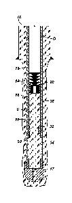
in the flow bore
uphole of the insert.
1
Date Recue/Date Received 2020-07-17
Atty. Dkt. No.: 205-0742US (6588-US)
[0007] The first plug is deployable down the tubing at least behind the
cement and is
seatable on the first seat. The first plug seated in the insert is configured
to prevent fluid
communication through the flow bore from the uphole end to the downhole end.
The
insert with the seated first plug is movable from the first position to a
second position in
response to a first application of the applied pressure releasing the
releasable connection.
The insert in the second position is configured to permit fluid communication
through the
flow bore.
[0008] The second plug is deployable down the tubing behind the second plug
and is
seatable on the second seat in the flow bore of the tool. The seated second
plug is
configured to isolate a second application of the applied pressure from
passing to the
downhole end of the tool. The second plug is self-removable in the tool to
reestablish fluid
communication through the flow bore of the tool.
[0009] The first plug can comprise a bottom member and a top member. The
bottom
member can have a passage therethrough, and the passage can have a closure
closing the
passage. The bottom member is deployable down the tubing ahead of the cement
and is
seatable on the first seat. The closure of the bottom member is opened in
response to an
initial application of the applied pressure against the seated bottom member
before the
first application. The top member is deployable down the tubing behind the
cement and is
configured to close fluid communication through the passage in the bottom
member.
[0010] The first plug can comprise a wiper dart having a head that is
configured to seat in
the first seat of the insert.
[0011] The insert can comprise a sleeve disposed in the flow bore. The
sleeve can have a
fluid passage therethrough with the first seat formed therein. The sleeve can
define a
bypass port communicating the fluid passage downhole of the first seat outside
the sleeve.
[0012] The flow bore of the tool can define a relief therein. The insert in
the second
position can be spaced from the relief and can be configured to permit fluid
communication
in a space between the insert and the relief. The relief of the tool can
define a shoulder
toward the downhole end of the tool such that the shoulder can engage the
insert in the
second position. The shoulder can define a first castellation configured to
engage a second
castellation of the insert.
2
Date Recue/Date Received 2020-07-17
Atty. Dkt. No.: 205-0742US (6588-US)
[0013] The second plug can comprise a self-removable material selected from
the group
consisting of a dissolvable material, an erodible material, a disintegrable
material, a
degradable material, an aluminum, a reactive metal, a magnesium alloy, a
degradable
composite polymer, a polystyrene, an elastomer, a resin, an adhesive, a
polyester, a
polymide, a thermoplastic polymer, a polyglycolide, a polyglycolic acid, and a
thermosetting
polymer.
[0014] The temporary connection can comprise one or more shear pins
disposed
between the insert and the flow bore of the tool.
[0015] According to the present disclosure, a method comprises: cementing
tubing in a
wellbore with cement by: pumping the cement through a flow bore of a tool
disposed on
the tubing, and seating a first plug at least behind the cement on a first
seat in a first
position in the flow bore of the tool; creating a wet shoe track by: moving
the first seat from
the first position to a second position in the flow bore with a first
application of applied
pressure against the seated first plug, and bypassing fluid communication
through the flow
bore of the tool around the seated first plug in the moved first seat; and
testing the
cemented tubing by: seating a second plug in a second seat in the flow bore of
the tool
uphole of the first seat, subjecting the cemented tubing to a second
application of applied
pressure against the seated second plug, and reestablishing fluid
communication through
the flow bore of the tool by self-removing the second plug from the second
seat.
[0016] Cementing the tubing in the wellbore with the cement by seating the
first plug at
least behind the cement on the first seat can comprise seating a bottom member
of the first
plug ahead of the cement on the first seat, breaching a flow passage through
the bottom
member, passing the cement through the flow passage, and seating a top member
of the
first plug behind the cement in the flow passage of the bottom member.
[0017] Moving the first seat from the first position to the second position
in the flow bore
with the first application of applied pressure against the seated first plug
can comprise
releasing a temporary connection retaining the first seat in the first
position inside the flow
bore with the first application of applied pressure against the seated first
plug.
[0018] Moving the first seat from the first position to the second position
in the flow bore
with the first application of applied pressure against the seated first plug
can comprise
3
Date Recue/Date Received 2020-07-17
Atty. Dkt. No.: 205-0742US (6588-US)
shifting an insert having the first seat from the first position to a relief
of the flow bore in
the second position.
[0019] Bypassing the fluid communication through the flow bore of the tool
around the
seated first plug in the moved first seat can comprise bypassing the fluid
communication
from the relief of the flow bore through a side port defined in the insert
downhole the first
seat.
[0020] The foregoing summary is not intended to summarize each potential
embodiment
or every aspect of the present disclosure.
BRIEF DESCRIPTION OF THE DRAWINGS
[0021] Figs. 1A-1C illustrate an assembly during steps of a cementing
procedure
according to the present disclosure.
[0022] Figs. 2A-2C illustrate another assembly during steps of a cementing
procedure
according to the present disclosure.
[0023] Figs. 3A-3C illustrate a wet shoe assembly of the present disclosure
during stages
of operation.
[0024] Figs. 4A-4C illustrate another wet shoe assembly of the present
disclosure during
stages of operation.
DETAILED DESCRIPTION OF THE DISCLOSURE
[0025] As disclosed herein, a wet shoe tool according to the present
disclosure is used to
produce bypass flow around wiper plug(s) to create a wet shoe track, where
unset or no
cement is left in a tubing section between a float collar and a shoe after a
primary cement
job. The wet shoe tool can be used for a number of applications, such as plug-
and-perf
applications, cementing liners and long strings, horizontal and vertical
wells, etc.
[0026] The wet shoe tool provides a positive indication of cement
displacement and
wiper plug location. Adjustable shear values can be used in the wet shoe tool
to provide a
clear indication that wiper plug(s) have landed and that shearing events have
occurred.
For example, the tool can include an insert with a seat that matches the wiper
plug. The
insert can be configured to shear free with an adjustable and configurable
shear value to
meet the application at hand.
4
Date Recue/Date Received 2020-07-17
Atty. Dkt. No.: 205-0742US (6588-US)
[0027] The wiper plug provides a positive indication upon landing at the
tool, and
applying pressure causes the shear insert to shift downward. At this point,
excess
displacement fluid bypasses the wiper plug and is pumped down through the shoe
track
and out of the toe to create a wet shoe.
[0028] After the wet shoe track is established, integrity of the tubing,
casing, liner, or the
like can be performed using a self-removing plug landed in a seat of the wet
shoe tool.
Once the testing is complete and the plug is removed, the re-established fluid
circulation
allows for other operations to be performed without requiring tubing-conveyed
perforating to be performed in the casing to open of flow path. For example,
wireline
perforating guns and composite plugs can be pumped down to begin stimulation
operations. If desired, the first stimulation operation can be performed
through the wet
shoe tool.
[0029] Figs. 1A-1C illustrate an assembly 10 during steps of a cementing
procedure
according to the present disclosure. Tubing 16 is being cemented in a borehole
12. The
tubing 16 referred to herein may be casing, production tubing, liner,
tubulars, or the like. A
wet shoe tool 30 is disposed on the tubing 16 and can be used with or part of
a casing
shoe/landing collar. For example, the wet shoe tool 30 can be disposed above a
hydraulic
landing collar, float shoe, or the like.
[0030] The wet shoe tool 30 is used for performing a wet shoe application,
which is an
operation that opens the flow path through the casing shoe after cementing.
Once cement
operations are complete, a wiper plug 20 lands in the wet shoe tool 30.
Operators apply
pressure to predetermined level to activate the tool 30 and open an internal
bypass so fluid
can pass through the tool 30. The opened fluid bypass allows operators to
displace the
cement and clear the float shoe, leaving a desired wet shoe track.
[0031] As shown in Fig. 1A, for example, an initial fluid slug followed by
cement C has
been pumped down through the bore 18 of the tubing 16, past a wet shoe tool
30, out the
shoe 17, and into the annulus 14 of the borehole 12. The shoe 17 may be a one-
way valve
or a check valve, such as a float valve/collar, that permits fluid flow out of
the tubing 16 and
into the borehole 12, while preventing fluid flow into the assembly 10 from
the borehole
12. The cement may be supplied through a work string (not shown) or the tubing
16 if the
work string is removed.
Date Recue/Date Received 2020-07-17
Atty. Dkt. No.: 205-0742US (6588-US)
[0032] A wiper plug 20 is pumped down the bore 18 of the tubing 16 behind the
cement C
using a displacement fluid D. The wiper plug 20 as disclosed herein may be any
conventional cement/wiper plug used in well cementing operations known in the
art.
[0033] Eventually, as shown in Fig. 1B, the wiper plug 20 reaches a landing
sleeve or
insert 32 in the wet shoe tool 30. Pressure applied behind the wiper plug 20
activates the
wet shoe tool 30 by shifting the landing insert 32 into a bypass 34 of the
tool 30, as shown
in Fig. 1C. The displacement fluid D can now pass through the wet shoe tool 30
and out the
assembly 10 via the bypass 34 to create a wet shoe track 15, which may have
benefits in
some implementations disclosed herein. For example, fluid communication is now
established through the tubing 16 so additional operations can be performed
without the
need to perforate the tubing 16.
[0034] During use, the tubing 16 must withstand pressures for which the
tubing 16 is
designed. To test the integrity of the cemented tubing 16, the wet shoe tool
30 includes a
landing seat 36 for receiving a plug 38 after the wiper plug 20 has landed in
the tool 30, the
insert 32 has shifted, and the bypass 34 has been opened. The plug 38 enables
a full
pressure test to be performed on the tubing 16 at a pressure level above the
pressure used
open the fluid flow through the wet shoe tool 30 after cementing.
[0035] To do the test, the plug 38, such as a ball, is pumped down the
tubing 16 to the wet
shoe tool 30 and lands in the seat 36 in the tool 30 so the plug seat 36 and
the plug 38 can
isolate the tubing 16 above the wet show tool 30. Pressure applied against the
seated plug
38 can then be used to test the integrity of the cemented tubing 16 to desired
test levels. A
full pressure check can be completed by allowing operators to cycle and
monitor pressure
pumped in the tubing 16 behind the seated plug 36 to assess the integrity of
the tubing 16.
[0036] The plug 38 is self-removing and will then dissolve away or
otherwise be
removed. Once the plug 38 is removed, fluid circulation is re-established
through the wet
shoe tool 30, allowing for the pump down of perforating guns, composite plugs,
and the like
for other operations to be performed. Being self-removing, the plug 38 is
composed of a
self-removable material that dissolves, disintegrates, or otherwise removes in
time to re-
establish flow through the tubing's bore 18 so subsequent operations can be
performed.
Reference herein to a self-removable material is meant to encompass any
materials
designed to dissolve, erode, disintegrate, or otherwise degrade over time
and/or in certain
6
Date Recue/Date Received 2020-07-17
Atty. Dkt. No.: 205-0742US (6588-US)
wellbore conditions due to heat, temperature, hydrocarbon composition,
introduced
solvent, applied acid, or other factors. For example, the plug 38 can be
composed of a
dissolvable, degradable, disintegrable, or other self-removable material known
in the art
when subjected to appropriate conditions, such as a temperature for a period
of time, an
introduced acid or other fluid, the existing wellbore fluid, etc. For example,
the material of
the plug 38 can be aluminum, a reactive metal, a magnesium alloy, a degradable
composite
polymer, a polystyrene, an elastomer, a resin, an adhesive, a polyester, a
polymide, a
thermoplastic polymer, a polyglycolide, a polyglycolic acid, a thermosetting
polymer, or the
like, such as used for fracture balls.
[0037] Figs. 2A-2C illustrate another assembly 10 during steps of a
cementing procedure
according to the present disclosure. Again, tubing 16 is being cemented in a
borehole 12.
The cement C may be supplied through a work string (not shown) or through the
tubing 16
if the work string is removed, and the cement C can be pumped behind a bottom
wiper plug
22 and ahead of a top wiper plug 28. The wiper plugs 22, 28 as disclosed
herein may be
any conventional cement/wiper plugs used in well cementing operations known in
the art.
[0038] As shown herein Fig. 2A, an initial fluid slug followed by a bottom
wiper plug 22
and cement C has been pumped down through the bore 18 of the tubing 16. As
shown in
Fig. 2A, the bottom wiper plug 22 is pumped down the bore 18 of the tubing 16
ahead of
the cement C. The bottom wiper plug 20 can be launched from a cementing head,
displacing fluids through the tubing 16 while preventing cement contamination.
[0039] The bottom wiper plug 22 is pumped until it lands in the landing
insert 32 of the
wet shoe tool 30. A passage 24 through the bottom plug 22 has a closure 26
that has been
opened by pressure, allowing the cement C pumped down through the bore 18 of
the
tubing 16 to pass through the bottom wiper plug 22, out the shoe 17, and into
the annulus
14 of the borehole 12. The closure 26 can be a breachable element, such as a
rupture disc,
typically used on a bottom wiper plug.
[0040] Behind the cement, the top wiper plug 28 is pumped down the tubing
bore 18
using a displacement fluid D, such as water. The top wiper plug 28 can be a
stinger dart
that is pumped behind cement and wipes the inside of the tubing 16, providing
a
mechanical barrier between the cement C and spacer fluids D. Eventually, as
shown in Fig.
2A, the top wiper plug 28 reaches the bottom wiper plug 22 and closes the
fluid passage 24
7
Date Recue/Date Received 2020-07-17
Atty. Dkt. No.: 205-0742US (6588-US)
through the bottom plug 22. For example, a head of the top wiper plug 28 can
fit into the
plug's passage 24 and can latch therein.
[0041] After cementing the tubing 16 in the borehole 12, fluid flow through
the end of the
tubing 16 may be established to form a wet shoe track for conducting
subsequent
operations. In particular, pressure applied behind the wiper plugs 22, 28
activates the wet
shoe tool 30 by shifting the landing insert 32 into the bypass 34 of the tool
30, as shown in
Fig. 2C.
[0042] The displacement fluid D can now pass through the wet shoe tool 30
to create a
wet shoe track 15, which may have benefits in the implementations disclosed
herein. For
example, fluid communication is now established through the tubing 16 so
additional
operations can be performed without the need to perforate the tubing 16.
[0043] To test the integrity of the cemented tubing 16, a plug 38, such as
a ball, is pumped
down the tubing 16 to the wet shoe tool 30 and lands in a seat 36 in the tool
30. Pressure
applied against the seated plug 38 can then be used to test the integrity of
the cemented
tubing 16 to desired test levels. Again, the plug 38 is composed of a self-
removable
material that dissolves, disintegrates, or otherwise removes in time to re-
establish flow
through the tubing's bore 18 so subsequent operations can be performed.
[0044] Figs. 3A-3C illustrate a wet shoe assembly of the present disclosure
during stages
of operation. The assembly includes a wet shoe tool 100 and plugs 120, 130. A
tool
housing 102 has a bore 104 for flow therethrough. The bore 104 includes a
bypass relief
105 and a landing shoulder 106 at a downhole end. Toward the uphole end, the
housing
102 includes a plug seat 108. Intermediate the plug seat 108 and landing
shoulder 106, a
sleeve or insert 110 is arranged in the bore 104 and is held by shear pins 116
or other
temporary retainer. The insert 110 includes a through-bore 112 with a landing
shoulder
114. Side ports 118 in the side of the insert 110 communicate the through-bore
112
outside the insert 110.
[0045] As shown in Fig. 3A, a wiper plug 120 having wiper fins along the
exterior lands in
the landing shoulder 114 of the insert 110. As shown here, the wiper plug 120
can include
a bottom wiper plug 122, which includes an internal passage 124 in which a top
wiper plug
128 is seated. Depending on the implementation, the bottom and top wiper plugs
122, 128
8
Date Recue/Date Received 2020-07-17
Atty. Dkt. No.: 205-0742US (6588-US)
can be pumped down together through the tubing 16 to the bore 104 of the
housing 104
behind the pumped cement.
[0046] Alternatively, the bottom wiper plug 122 can be pumped ahead of the
cement (not
shown), a closure 126, such as a breachable element or a rupture disc, in the
passage 124 of
the bottom plug 122 can be breached to permit the cement to flow through the
passage
124. For example, cement may be supplied at a pressure sufficient to
breach/rupture the
closure 126 in the bottom plug 122 (if necessary) and permit fluid flow
through the flow
passage 124 into the borehole 12. A predetermined amount of cement may be
supplied
into the borehole (12) to cement the tubing (16) therein. Eventually, the top
plug 126 can
be pumped behind the cement and can land in the passage 124 of the lower plug
120 to
seal fluid flow.
[0047] With the plug arrangement as shown in Fig. 3A, pumped fluid against
the plugs
122, 128 can break the releasable connections or shear pins 116, allowing the
insert 110 to
shift in the housing bore 104. For example, fluid may be supplied through the
tubing (16)
behind the plugs 122, 128 at a pressure sufficient to shear the pins 116 and
shift the insert
110 to the bore relief 105. The pressure readings of the system before and
after shearing
the pins 116 may provide an indication at surface that the insert 110 and
plugs 122, 128
are in the desired position.
[0048] As shown in Fig. 3B, the wet shoe tool 100 is shown once fluid flow
is re-
established to form a "wet shoe," which occurs when cement does not set around
the float
shoe (17) so that fluid may continue to be flowed through the float shoe (17)
after the
system is cemented in the borehole (12). Fluid is supplied against the seated
plugs 122,
128 and the insert 110 at a pressure sufficient to release the releasable
connection or shear
pins 116. The insert 110 then moves in the flow bore 104 to a position where a
lower
shoulder of the insert 110 engages a landing shoulder 106 in the flow bore
104. Movement
of the insert 110 also allows the plug 122, 128 to move out of sealed
engagement with any
polished bore inside the tool 100.
[0049] As shown in Fig. 3B, the insert 110 lands on the landing shoulder
106, and the fins
of the plugs 122, 128 are spaced from the bypass relief 105. Castellations
107, 117 may
prevent rotation. Fluid may now flow around the plugs 122, 128 and pass to the
bypass
relief 105. The side ports 118 in the insert 110 can communicate the flow from
the bypass
9
Date Recue/Date Received 2020-07-17
Atty. Dkt. No.: 205-0742US (6588-US)
relief 105 to the downhole end of the bore 104. This fluid communication
allows for a wet
shoe track to be created so additional operations can be performed as
disclosed herein.
The reduction in pressure and/or the circulation of fluid flow into the
borehole (12) can
provide another indication at the surface of the position of the plugs 122,
128 and the
insert 110, and that fluid communication through the system is open to conduct
subsequent operations.
[0050] The cement is allowed to set so pressure testing can then be
performed on the
tubing (16). To test the integrity of the cemented tubing (not shown) on which
the tool 100
is connected, the flowpath through the wet shoe tool 100 allows a self-
removing plug 130,
such as a ball, to be pumped down and seated on the plug seat 108 in the tool
100, as
shown in Fig. 3C. Pressure applied against the seated plug 130 can then be
used to test the
integrity of the cemented tubing to desired test levels. As disclosed herein,
the plug 130 is
composed of a self-removing material that dissolves, disintegrates, or
otherwise removes
in time to re-establish flow through the tool's bore 104 so subsequent
operations can be
performed. Eventually, the plug 108 will be removed (e.g., dissolve over time)
so that
additional operations (plug and perf, ball drop frac, etc.) can be performed
in the borehole
(12) downhole of the open wet shoe tool 100.
[0051] With the wet shoe track established, fluid may be supplied through
the wet shoe
tool 100 into the borehole (12). In this way, a number of additional
operations can be
performed. For example, a perforating device may be pumped through the wet
shoe tool
100 on a wireline to perforate one or more sections of the borehole (12). In
another
example, a plugging device may be pumped through the wet shoe tool 100 on a
wireline to
seal one or more downhole sections of the borehole (12). In yet another
example, a
perforating, fracturing, and/or another liner hanging operation may be
conducted. The
insert 110 can be composed of aluminum or composite material for ease in
milling out
when the plugs 122, 128 are milled out.
[0052] Figs. 4A-4C illustrate another wet shoe assembly of the present
disclosure during
stages of operation. Again, the assembly includes a wet shoe tool 100 and
plugs 120, 130.
As before, a tool housing 102 has a bore 104 for flow therethrough. The bore
104 includes
a bypass relief 105 and a landing shoulder 106 at a downhole end. Toward the
uphole end,
the housing 102 includes a plug seat 108. Intermediate the plug seat 108 and
the landing
Date Recue/Date Received 2020-07-17
Atty. Dkt. No.: 205-0742US (6588-US)
shoulder 106, a sleeve or insert 110 is arranged in the bore 104 and is held
by shear pins
116 or other releasable connection or retainer. The insert 110 includes a
through-bore 112
with a landing shoulder 114. Side ports 118 in the side of the insert 110
communicate the
through-bore 112 outside the insert 110.
[0053] As shown in Fig. 4A, a wiper plug 120 having wiper fins lands in the
landing
shoulder 114 of the insert 110. As shown here, the wiper plug 120 includes a
head or nose
129 that seats in the landing shoulder 114. Depending on the implementation,
the wiper
plug 120 can be pumped behind the cement and can land in the seat 114 of the
insert 110.
For example, the wiper plug 120 in Figs. 4A-4C can be stinger dart, featuring
a seal ring on
the nose 129, which enabling the seated plug 120 to withstand high
differential pressures
when latched into the seat 114 by a corresponding snap ring.
[0054] With the plug 120 seated as shown in Fig. 4A, pumped fluid against
the plug 120
can break the releasable connection or shear pins 116, allowing the insert 110
to shift in
the housing bore 104. As shown in Fig. 4B, the insert 110 lands on the landing
shoulder
106, and the fins 122 of the plug 120 are spaced from the bypass relief 105.
Flow through
the housing bore 104 can pass around the plug 120 and to the bypass relief
105. The side
ports 118 in the insert 110 can communicate the flow from the bypass relief
105 to the
downhole end of the bore 104. This fluid communication allows for a wet shoe
track to be
created so additional operations can be performed as disclosed herein.
[0055] As before, castellations 107, 117 may prevent rotation. Likewise,
the pressure
increase and reductions and/or the circulation of fluid flow into the borehole
(12) can
provide indications to operators at the surface of the position of the plug
120 and the insert
110, and that fluid communication through the system is open to conduct
subsequent
operations.
[0056] To test the integrity of the cemented tubing (not shown) on which
the tool 100 is
deployed, a plug 130, such as a ball, is pumped down to the wet shoe tool 100
and lands in
the plug seat 108 in the tool 100. Pressure applied against the seated plug
130 can then be
used to test the integrity of the cemented tubing to desired test levels. The
plug 130 is
composed of a material that dissolves, disintegrates, or otherwise removes in
time, re-
establish flow through the tool's bore 104 so subsequent operations can be
performed.
11
Date Recue/Date Received 2020-07-17
Atty. Dkt. No.: 205-0742US (6588-US)
[0057] The foregoing description of preferred and other embodiments is not
intended to
limit or restrict the scope or applicability of the inventive concepts
conceived of by the
Applicants. It will be appreciated with the benefit of the present disclosure
that features
described above in accordance with any embodiment or aspect of the disclosed
subject
matter can be utilized, either alone or in combination, with any other
described feature, in
any other embodiment or aspect of the disclosed subject matter.
[0058] In exchange for disclosing the inventive concepts contained herein,
the Applicants
desire all patent rights afforded by the appended claims. Therefore, it is
intended that the
appended claims include all modifications and alterations to the full extent
that they come
within the scope of the following claims or the equivalents thereof.
12
Date Recue/Date Received 2020-07-17