Note : Les descriptions sont présentées dans la langue officielle dans laquelle elles ont été soumises.
CA 03089040 2020-07-17
WO 2019/147514
PCT/US2019/014397
SYSTEM FOR PREHEATING GLASS MELTING FURNACE BATCH MATERIALS
BACKGROUND
a. Technical Field
This disclosure relates to systems for preheating batch materials before
introduction
to a glass melting furnace. In particular, the disclosure relates to a system
for preheating batch
materials in which the mass flow and/or temperature of exhaust fluids through
the preheater
and/or furnace charger are controlled in order to maximize energy transfer to
the batch materials
while protecting ductwork leading to and from the preheater and other
components.
b. Background Art
In a glass melting furnace system, a preheater is often used to preheat batch
materials
that are then fed to a glass melting furnace along with other unheated batch
materials. Heat in
the preheater is generated, at least in part, by directing at least a portion
of the exhaust fluid from
the furnace to the preheater through ductwork. It is desirable to both
maximize energy transfer
from the exhaust fluid to the batch materials and, at the same time, protect
the ductwork leading
to and from the preheater and other components from excessive temperatures.
Careful control is
required to accomplish these goals because changes in the quality (e.g.,
moisture content and/or
size) of the batch materials (particularly cullet) can substantially change
the amount of heat
transfer to the batch materials and, as a result, the temperature of exhaust
fluids.
The inventors herein have recognized a need for a furnace system that will
minimize
and/or eliminate one or more of the above-identified deficiencies.
BRIEF SUMMARY OF THE DISCLOSURE
This disclosure relates to systems for preheating glass melting furnace batch
materials. In particular, the disclosure relates to a system for preheating
batch materials in which
the mass flow and/or temperature of exhaust fluids through the preheater are
controlled in order
to maximize energy transfer to the batch materials and protect ductwork
leading to and from the
preheater and other components. The batch materials may comprise raw materials
such as silica
sand, limestone, soda ash or other raw materials, as well as recycled glass
(i.e., cullet) or
mixtures of the foregoing.
1
CA 03089040 2020-07-17
WO 2019/147514
PCT/US2019/014397
A system for preheating batch materials prior to delivery to a glass melting
furnace
in accordance with one embodiment of the present teachings includes a
preheater configured to
receive unheated batch materials and to deliver heated batch materials. The
preheater includes a
primary outlet configured to exhaust fluid from the preheater and a primary
inlet configured to
receive exhaust fluids from the glass melting furnace and exhaust fluids
recirculated from the
primary outlet of the preheater. The system further includes a cyclonic
separator having an inlet
in fluid communication with the primary outlet of the preheater and an outlet
configured to
exhaust fluids from the cyclonic separator. The system further includes a fan
in fluid
communication with the outlet of the cyclonic separator. The system further
includes a pressure
sensor configured to generate a pressure signal indicative of a drop in
pressure between the inlet
and the outlet of the cyclonic separator and a temperature sensor configured
to generate a
temperature signal indicative of a temperature at the outlet of the cyclonic
separator. The system
further includes a cyclonic flow controller configured to control a speed of
the fan responsive to
the pressure signal and the temperature signal.
A system for preheating batch materials prior to delivery to glass melting
furnace in
accordance with another embodiment of the present teachings includes a
preheater configured to
receive unheated batch materials and to deliver heated batch materials. The
preheater includes a
primary outlet configured to exhaust fluid from the preheater and a primary
inlet configured to
receive exhaust fluids from the glass melting furnace and exhaust fluids
recirculated from the
primary outlet of the preheater. The system further includes a first valve
configured to control a
first amount of exhaust fluid from the preheater delivered to a flue for
combination with exhaust
fluid from the glass melting furnace and a second valve configured to control
a second amount of
exhaust fluid from the preheater recirculated to the inlet of the preheater.
The system further
includes a temperature sensor configured to generate a temperature signal
indicative of a
temperature of fluids within a duct coupled to the inlet of the preheater and
an inlet temperature
controller configured to control the first valve and the second valve
responsive to the
temperature.
A system for preheating batch materials prior to delivery to a glass melting
furnace
in accordance with another embodiment of the present teachings includes a
preheater configured
to receive unheated batch materials and to deliver heated batch materials. The
preheater includes
a primary outlet configured to exhaust fluid from the preheater and a primary
inlet configured to
2
CA 03089040 2020-07-17
WO 2019/147514
PCT/US2019/014397
receive exhaust fluids from the glass melting furnace and exhaust fluids
recirculated from the
primary outlet of the preheater. The system further includes a charger
configured to receive the
heated batch materials from the preheater and feed the heated batch materials
to the glass melting
furnace. A first recirculation duct provides exhaust fluids from the charger
to a second
recirculation duct coupled to the inlet of the preheater and carrying the
exhaust fluids from the
glass melting furnace and the exhaust fluids recirculated from the primary
outlet of the preheater.
The system further includes a first temperature sensor configured to generate
a first temperature
signal indicative of a first temperature of fluids within the second
recirculation duct and a second
temperature sensor configured to generate a second temperature signal
indicative of a second
temperature of the fluids within the second recirculation duct at a location
in the duct upstream
of where the first temperature is obtained. The system further includes a
valve configured to
control an amount of fluid in the second recirculation duct that is diverted
to the charger and a
charger temperature controller configured to control the valve responsive to
the first and second
temperatures.
A system for preheating batch materials in accordance with the present
teachings is
advantageous relative to conventional systems. In particular, the inventive
system enables
efficient transfer of energy from exhaust fluids to batch materials in the
preheater while also
protecting ductwork leading to and from the preheater from excessive
temperatures.
The foregoing and other aspects, features, details, utilities, and advantages
of the
disclosed system will be apparent from reading the following detailed
description and claims,
and from reviewing the accompanying drawings illustrating features of this
system by way of
example.
BRIEF DESCRIPTION OF THE DRAWINGS
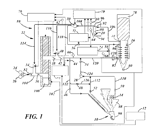
Figure 1 is a schematic drawing of a furnace system incorporating a system for
preheating cullet in accordance with one embodiment of the present teachings.
Figure 2 is a graph depicting a split range control profile of target flow
rate and valve
position in accordance with one embodiment of the present teachings.
Figure 3 is a graph depicting a split range control profile of valve positions
in
accordance with one embodiment of the present teachings.
3
CA 03089040 2020-07-17
WO 2019/147514
PCT/US2019/014397
DETAILED DESCRIPTION
Referring now to the drawings wherein like reference numerals are used to
identify
identical components in the various views, Figure 1 illustrates a furnace
system 10 in accordance
with one embodiment of the present teachings. System 10 is provided to melt
raw materials for
use in forming objects or products. System 10 may comprise, for example, a
glass melting
furnace system for use in melting silica sand, soda ash (sodium carbonate),
limestone and other
batch materials such as cullet (recycled broken glass) into molten glass.
System 10 may include
a furnace 12, a batch screw feeder 14, a batch materials preheater 16, a
charger 18, a cyclonic
separator 20, a duct system 22, a plurality of fans 24, 26, 28, 30, a
plurality of valves 32, 34, 36,
38, 40, 42, 44, 46, 48, 50, 52, 54, 56, 58, pressure sensors 60, 62
temperature sensors 64, 66, 68
and various controllers 70, 72, 74, 76, 77.
Furnace 12 is provided to melt raw materials. Furnace 12 may comprise a glass
melting furnace that melts batch materials including silica sand, soda ash,
limestone and cullet
into molten glass. Furnace 12 may have an operating temperature of about 1565
degrees Celsius
(2850 degrees Fahrenheit). Furnace 12 may generate heat using natural gas and
preheated
combustion air. Furnace 12 may also augment the heat using an electric boost
system. Excess
heat may be exhausted from furnace 12 through duct system 22.
Batch screw feeder 14 is provided to direct raw batch materials (e.g., silica
sand,
soda ash and limestone) into charger 18. Although a screw feeder 14 is shown
in the illustrated
embodiment, it should be understood that a variety of mechanisms including
chutes, conveyors
and other structures may be used in addition to, or as an alternative to,
screw feeder 14 to deliver
batch material from one or more silos (not shown) to charger 18. Screw feeder
14 and/or other
components of the batch delivery system may be controlled using conventional
electromechanical controls that regulate the amount of batch material provided
to charger 18
based on feedback signals from sensors used to monitor various conditions of
the furnace 10,
charger 18, or other structures in system 10.
Preheater 16 is provided to preheat materials before they are introduced into
furnace
12 to improve the operating efficiency of furnace 12. In the glass melting
furnace system
referenced above, preheater 16 comprises a batch materials preheater that is
configured to
receive unheated batch materials and preheat the batch materials before
delivering heated batch
materials to furnace 12. The batch materials preheater 16 may comprise a
direct contact raining
4
CA 03089040 2020-07-17
WO 2019/147514
PCT/US2019/014397
bed counterflow preheater in which unheated batch materials are introduced at
one end of the
preheater 16 and travel through the preheater 16 under gravitational forces
while heat is
introduced into the opposite end of preheater 16 and flows in the opposite
direction to the batch
materials. It should be understood, however, that other conventional forms of
preheaters 16, for
cullet, raw batch materials, or the like may alternatively be used in glass
melting furnace
systems. Batch materials may be introduced to preheater 16 through a batch
materials inlet 78
from one or more silos (not shown) and may exit an opposite end of the
preheater 16 through a
batch materials outlet 80 and be provided to charger 18. In between, batch
materials flow
through the preheater 16 around deflector plates. Heat, in the form of exhaust
fluids from
furnace 12, preheater 16 and charger 18 may be introduced to preheater 16
through a primary
inlet 82 and exhausted through a primary outlet 84. As discussed hereinbelow,
exhaust fluids
may also be introduced to preheater 16 from furnace 12, preheater 16 and
charger 18 through a
bypass inlet 86 disposed between primary inlet 82 and primary outlet 84
relative to the direction
of batch material flow in preheater 16.
Charger 18 is provided to feed a mixture of raw batch materials and cullet
into
furnace 12. Charger 18 may include a hopper 88 and a feed chamber 90. Hopper
88 is provided
to combine streams of raw batch materials from batch screw feeder 14 and batch
materials from
preheater 16 and to direct the combined stream into feed chamber 90. Feed
chamber 90 has an
inlet end coupled to the outlet end of hopper 88. The inlet end is configured
to receive the
combined stream of raw batch materials and heated batch materials from hopper
88. Feed
chamber 90 also has an outlet end through which a mixture of the raw batch
material and the
heated batch material is discharged from the feed chamber 90 into a molten
bath in furnace 12
using, for example, vibratory movements or a reciprocating pushing movement.
Cyclonic separator 20 is provided to separate fine particulates, including
glass fines,
from the exhaust fluids generated by preheater 16. Cyclonic separator 20
defines an inlet 92
configured to receive exhaust fluids from the primary outlet 84 of the
preheater 16. Cyclonic
separator 20 further defines outlets 94, 96, at opposite ends of a cylindrical
container 98
configured to discharge particulates and cleaned exhaust fluids, respectively.
The configuration
of the inlet 92 and shape of the container 98 establish a high speed rotating
air flow within the
container 98 that causes particulates in the exhaust fluid to be removed from
the air flow and
drop the bottom of the container where they may be removed through outlet 94
while cleaner air
5
CA 03089040 2020-07-17
WO 2019/147514
PCT/US2019/014397
is exhausted from outlet 96. The particulates exiting outlet 94 may be
directed to an inlet to
batch screw feeder 14 to be mixed with the raw batch materials.
Duct system 22 is provided to route fluids between furnace 12, preheater 16,
charger
18 and other components (not shown) of system 10 as well as the atmosphere
(for air intake and
byproduct exhaustion). Duct system 22 is made from materials sufficient to
withstand the
anticipated operating temperatures in the components of system 10 and may be
made from steel
in some embodiments. Fans, including fans 24, 26, 28, 30 may be used to
introduce fluids to
ducts within duct system 22 or to move fluids within duct system 22.
Mechanically or
electrically controlled valves, including valves 32, 34, 36, 38, 40, 42, 44,
46, 48, 50, 52, 54, 56,
58 may be disposed within duct system 22 to control the amount of fluid
flowing to and from
various components of furnace system 10. In the illustrated embodiment, duct
system 22
includes a flue channel 100, a furnace exhaust duct 102, an air intake duct
104, a preheater
exhaust duct 106, a cyclonic separator exhaust duct 108, charger exhaust ducts
110, 112,
recirculation ducts 114, 116, 118, 120, 122, 124 and bypass ducts 126, 128. It
should be
understood, however, that additional ducts may form a part of duct system 22.
Flue channel 100 is provided to capture exhaust gases from furnace 12 and
preheater
16. Flue channel 100 recycles a portion of the exhaust gases for use within
portions of system 10
such as in preheating batch materials in preheater 16 or materials in charger
18. Flue channel
100 also provides a means for cooling the exhaust gases prior to reuse within
system 10 and/or
treatment by downstream filters, scrubbers and other energy recovery and
pollution control
equipment prior to exhausting the remaining fluids to atmosphere.
Furnace exhaust duct 102 is provided to transport exhaust fluids from furnace
10 to
flue channel 100. Duct 102 is connected to flue channel 100 proximate one end
of flue channel
100. Exhaust duct 102 may have a different composition in terms of material
composition, shape
(e.g., thickness), or other characteristics relative to other ducts within
duct system 22 in order to
adequately handle the relatively high temperature exhaust fluids exhausted
from furnace 12.
Air intake duct 104 is provided to introduce ambient air or another fluid into
flue
channel 100 for mixing with furnace exhaust gases to cool the exhaust gases.
In the illustrated
embodiment, air intake duct 104 is connected to, and receives fluids from,
recirculation duct 114
and may therefore provide ambient air, recirculated fluids, or a mixture of
the two depending on
the positions of valves 32, 34.
6
CA 03089040 2020-07-17
WO 2019/147514
PCT/US2019/014397
Preheater exhaust duct 106 and cyclonic separator exhaust duct 108 are
provided to
exhaust fluids from preheater 16 and cyclonic separator 20, respectively. Duct
106 extends
between primary outlet 84 of preheater 16 and inlet 92 of cyclonic separator
20. Duct 108
extends between outlet 96 of cyclonic separator 20 and fan 30.
Charger exhaust ducts 110, 112 are provided to exhaust fluids from the hopper
88
and feed chamber 90, respectively, of charger 18. Duct 110, extends from
hopper 88 to fan 28.
Duct 112 extends from feed chamber 90 and intersects duct 110 between hopper
88 and fan 28.
Recirculation ducts 114, 116, 118, 120, 122, 124 are provided to recirculate
exhaust
fluids from furnace 12, preheater 16, charger 18 and cyclonic separator 20
within system 10.
Recirculation duct 114 transmits a portion of the exhaust fluids from
preheater 16 (via cyclonic
separator 20) to flue channel 100 through air intake duct 104. Recirculation
duct 116 transmits
another portion of the exhaust fluids from preheater 16 (via cyclonic
separator 20) to
recirculation duct 120. Recirculation duct 118 transmits yet another portion
of the exhaust fluids
from preheater 16 (via cyclonic separator 20) directly to preheater 16 and
extends from fan 30 to
bypass inlet 86 of preheater 16. Recirculation duct 120 transmits a portion of
the mixed exhaust
gases of furnace 12 and preheater 16 (along with ambient air) for use in
preheater 16 and charger
18. Duct 120 extends from an outlet of flue channel 100 to primary inlet 82 of
preheater 16.
Recirculation duct 122 intersects duct 120 between the flue channel outlet and
the primary inlet
82 of preheater 16 and directs a portion of the fluid mixture in recirculation
duct 120 to feed
chamber 90 of charger 18. Finally, recirculation duct 124 also intersects duct
120 between the
flue channel outlet and the preheater primary inlet 82 and directs exhaust
fluids from hopper 88
and mixing chamber 90 of charger 18 to duct 120.
Bypass ducts 126, 128 are provided to redirect portions of fluids from
recirculation
ducts 122, 120, respectively, for specific uses. Bypass duct 128 extends
between recirculation
ducts 118, 120 and directs a portion of the fluid mixture in recirculation
duct 120 to recirculation
duct 118. Bypass duct 128 is connected to recirculation duct 120 between the
flue channel outlet
and the primary inlet 82 of preheater 16 and is connected to recirculation
duct 118 between fan
and the bypass inlet 86 of preheater 16. Bypass duct 126 extends between
recirculation duct
122 and charger exhaust duct 112 and directs a portion of the fluid mixture in
recirculation duct
30
122 to charger exhaust duct 112 in order to maintain temperatures within
charger exhaust ducts
110, 112 at a predetermined level to avoid condensation within ducts 110, 112.
7
CA 03089040 2020-07-17
WO 2019/147514
PCT/US2019/014397
Fans 24, 26, 28, 30 are provided to draw fluids from one location and direct
those
fluids to another location within system 10. Fans 24, 26, are provided to
input ambient air from
the atmosphere into air intake duct 104 for mixing with furnace exhaust fluids
in flue channel
100. Fan 28 is provided to draw exhaust fluids from hopper 88 and feed chamber
90 of charger
18 and transmit those fluids into recirculation duct 124 for mixture with
other exhaust fluids
from furnace 10 and preheater 16 used in preheating batch materials in
preheater 16. Fan 30 is
provided to draw exhaust fluids from preheater 16 (through cyclonic separator
20) and direct
those fluids to recirculation ducts 114, 116, 118. In accordance with one
aspect of the present
disclosure discussed hereinbelow, the speed of fan 30 may be controlled in
order to control
exhaust fluid mass flow and temperatures within system 10.
Valves 32, 34, 36, 38, 40, 42, 44, 46, 48, 50, 52, 54, 56, 58 are provided to
control
fluid flow within the ducts of duct system 22. Valves 32, 34, 36, 38, 40, 42,
44, 46, 48, 50, 52,
54, 56, 58 may comprise butterfly valves and the position of each valve may be
changed using
conventional electromechanical controls under the direction of controllers
such as controllers 70,
72, 74, 76, 77. Valve 32 is provided to control the amount of ambient air
introduced to air intake
duct 104 (and ultimately to flue channel 100). Valve 34 is provided to control
the amount of
exhaust fluids from preheater 16 (through cyclonic separator 20) that are
introduced from
recirculation duct 114 to air intake duct 104 (and ultimately flue channel
100). Valve 36 is
provided to control the amount of fluids from air intake duct 104 introduced
into flue channel
100. Valve 38 is provided to control the amount of fluids introduced from flue
channel 100 into
recirculation duct 120. Valve 40 is provided to control the amount of exhaust
fluids from
preheater 16 (through cyclonic separator 20) that are introduced from
recirculation duct 116 into
recirculation duct 120. Valve 42 is provided to control the amount of fluids
introduced into
recirculation duct 120 from flue channel 100 and recirculation duct 116 that
are transmitted
downstream to devices such as preheater 16 and charger 18. Valve 44 is
provided to control the
amount of fluids that are transmitted from recirculation duct 120 downstream
through
recirculation duct 122 to charger 18. Valves 46, 48 are provided to control
the amount of fluids
that are transmitted from recirculation duct 122 to feed chamber 90 of charger
18 and through
bypass duct 126 to recirculation duct 112. Valves 50, 52 are provided to
control the amount of
exhaust fluids introduced from hopper 88 and feed chamber 90, respectively, of
charger 18 to
recirculation duct 110. Valve 54 is provided to control the amount of exhaust
fluids introduced
8
CA 03089040 2020-07-17
WO 2019/147514
PCT/US2019/014397
from recirculation duct 124 into recirculation duct 120. Valve 56 is provided
to control fluid
flow from fan 30 to bypass inlet 86 of preheater 16 and, in particular, the
amount of exhaust
fluids from preheater 16 (through cyclonic separator 20) that are transmitted
to bypass inlet 86 of
preheater 16. Finally, valve 58 is provided to control the amount of the
exhaust fluid mixture in
recirculation duct 120 that is redirected from primary inlet 82 of preheater
16 to bypass inlet 86
of preheater 16. In accordance with various aspects of the present disclosure
discussed
hereinbelow, the positions of one or more of valves 34, 40, 44, 56, and 58 may
be controlled in
order to control exhaust fluid mass flow and temperatures within system 10.
Pressure sensor 60 comprises a differential pressure sensor and is provided to
measure the drop in pressure between inlet 92 and outlet 96 of cyclonic
separator 20. Pressure
sensor 62 is provided to measure the pressure in recirculation duct 114.
Sensors 60, 62 may
comprise any of a variety of conventional pressure sensors including
piezoresistive,
piezoelectric, capacitive, resonant or other sensors. Pressure sensor 60
generates a pressure
signal indicative of a drop in pressure between inlet 92 and outlet 96 of
cyclonic separator 20 and
provides that signal to controller 70. Pressure sensor 62 generates a pressure
signal indicative of
the pressure in duct 114 and provides that signal to controller 76. Although
the illustrated
embodiment shows selected pressure sensors relevant to the present disclosure,
it should be
understood that other pressure sensors may be disposed throughout system 10
and used in
various control processes.
Temperature sensors 64, 66, 68 are provided to measure the temperature of
fluids at
various locations within duct system 22. Sensors 64, 66, 68 may comprise any
of a variety of
conventional temperature sensors including thermistors or thermocouples.
Sensor 64 measures
the fluid temperature of the exhaust fluids immediately downstream of outlet
96 of cyclonic
separator 20. Sensor 64 generates a temperature signal indicative of a
temperature at outlet 96 of
cyclonic separator 20 and provides that signal to controllers 70, 72, 74.
Temperature sensors 66,
68 are provided to measure the temperature of fluids at two locations within
recirculation duct
120. Temperature sensor 66 measures the temperature of fluids in duct 120 at a
location
upstream of temperature sensor 68. Temperature sensors 66, 68 generate
temperature signals
indicative of temperatures of fluids within duct 120 and provide those signals
to controllers 76,
77. Although the illustrated embodiment shows selected temperature sensors
relevant to the
9
CA 03089040 2020-07-17
WO 2019/147514
PCT/US2019/014397
present disclosure, it should again be understood that other temperature
sensors may be disposed
throughout system 10 and used in various control processes.
Controllers 70, 72, 74, 76, 77 are configured to control various components
within
system 10. In the illustrated embodiments, particular controllers will be
described for use in
controlling fan 30 and valves 34, 40, 44, 56, 58. It should be understood,
however, that
additional controllers may be used within system 10 for control of other
system components.
Further, although controllers 70, 72, 74, 76, 77 are illustrated as separate
controllers in the
illustrated embodiment, it should be understood that one or more of
controllers 70, 72, 74, 76, 77
may be integrated into a single controller and that one or more of controllers
70, 72, 74, 76, 77
may be subdivided into yet additional controllers responsible for a subset of
tasks associated with
a particular controller. Controllers 70, 72, 74, 76, 77 may comprise
programmable
microprocessors or application specific integrated circuits (ASICs).
Controllers 70, 72, 74, 76,
77 may include central processing units (CPU) and input/output (I/0)
interfaces through which
the controllers 70, 72, 74, 76, 77 may receive of input signals including
signals generated by
sensors 60, 62, 64, 66, 68 and generate output signals including those used to
control fan 30 and
valves 34, 40, 44, 56, 58. In accordance with the teachings disclosed herein,
controllers 70, 72,
74, 76, 77 may be configured (encoded) with sets of executable instructions
from a computer
program (i.e. software) to perform methods for controlling the mass flow and
temperature of
exhaust fluids within portions of system 10 and, in particular, for
controlling fan 30 and valves
34, 40, 44, 56, 58 to achieve control of the mass flow and temperatures.
Cyclonic flow controller 70 is provided to control fan 30 and, in particular,
the speed
of fan 30 in order to control the mass flow of exhaust fluids through
preheater 16 and cyclonic
separator 20. Controller 70 is configured to receive input signals from
pressure sensor 60,
temperature sensor 64 and temperature controller 72. Controller 70 is further
configured to
generate an output signal used to control fan 30 responsive to the pressure
signal from pressure
sensor 60 and the temperature signal from temperature sensor 64. In
particular, controller 70 is
configured to determine an actual flow rate through cyclonic separator 20
responsive to the
pressure signal (which evidences a drop in pressure across cyclonic separator
20) and
temperature signal (where increases in temperature are indicative of increases
in mass flow).
Controller 70 is further configured to receive a target flow rate signal from
temperature
controller 72 indicative of a desired fluid flow rate through cyclonic
separator 20. The target
CA 03089040 2020-07-17
WO 2019/147514
PCT/US2019/014397
flow rate signal is intended to reflect batch materials throughput rate
(furnace pull rate multiplied
by bath materials ratio) and batch materials quality (e.g., size and moisture
content). The target
flow rate can be set by an operator of system 10. As set forth hereinbelow,
however, temperature
controller 72 may also be configured to establish the target flow rate based
on one or more
variables in system 10. Controller 70 is further configured to adjust the
speed of fan 30 if the
actual flow rate meets a predetermined condition relative to the target flow
rate. For example, if
the actual flow rate exceeds the target flow rate, controller 70 may generate
a control signal
configured to reduce the speed of fan 30. If the actual flow rate is less than
the target flow rate,
controller 70 may generate a control signal configured to increase the speed
of fan 30.
Controller 70 may implement a proportional-integral-derivative (PD) control
algorithm for this
purpose. Finally, controller 70 may be configured to establish predetermined
speeds for fan 30
during predefined events including startup and shutdown of system 10 and
during emergencies.
Temperature controller 72 is provided to control the temperature of exhaust
fluids
through ducts 106, 108 in order to protect the ductwork, cyclonic separator 20
and fan 30 and to
optimize energy transfer to batch materials in preheater 16. Controller 72 is
configured to
receive an input signal from temperature sensor 64 (controller 72 may also
receive an operator
input indicative of a desired target flow rate). Controller 72 is configured
to generate output
signals in the form of a target flow rate signal indicative of a desired
target flow rate and a valve
control signal indicative of a commanded position for valve 56. As set forth
hereinabove, in
certain circumstances the target flow rate signal may be responsive to an
operator input selected
based on factors including batch materials throughput rate and batch materials
quality.
Controller 72, however, also has a mode of operation in which it is configured
to generate a
target flow rate responsive to the temperature measured by sensor 64 proximate
outlet 96 of
cyclonic separator 20. Controller 72 may be configured to implement the mode
in which the
target flow rate signal is generated responsive to the measured temperature
from sensor 64--as
opposed to using the operator input--under a variety of circumstances
including, for example, if
the measured temperature varies from a desired temperature more than a
predetermined amount
or shows signs of rapid change over time. Controller 72 is also configured to
generate a valve
control signal for controlling a position of valve 56 responsive to the
temperature signal. Valve
56 can be used to control temperature in ducts 106, 108 by controlling the
amount of exhaust
fluids from preheater 16 that are recirculated to bypass inlet 86 of preheater
16. Because fan 30
11
CA 03089040 2020-07-17
WO 2019/147514
PCT/US2019/014397
controls the flow rate through preheater 16 and the flow is constant at a
constant fan speed,
changing the position of valve 56 to increase or decrease the flow through
bypass inlet 86 of
preheater 16 causes a corresponding decrease or increase, respectively, in the
amount of exhaust
gases that are drawn into preheater 16 from recirculation duct 120. In this
manner, opening
valve 56 to increase flow through duct 118 to bypass inlet 86 of preheater 16
reduces the flow
from duct 120 to inlet 82 and the temperature of the exhaust fluids exiting
outlet 84 of preheater
16. Conversely, closing valve 56 to decrease flow through duct 118 to bypass
inlet 86 of
preheater 16 increases the flow from duct 120 to inlet 82 and the temperature
of the exhaust
fluids exiting outlet 84 of preheater 16. In an alternative embodiment,
controller 72 could be
configured to control a valve (not shown) that directs ambient air into the
mass flow entering,
within, or exiting preheater 16 to control the temperature. Referring to
Figure 2, in accordance
with some embodiments, controller 72 may be configured to generate the target
flow rate signal
and valve control signal in accordance with a predefined split range control
profile. The use of a
split range control profile allows smooth, bumpless transfer of the
manipulation of both the
target flow rate and valve position by establishing a mathematical
relationship between the two
values. In the illustrated profile, valve 56 moves from a fully open position
towards a closed
position dependent on the extent of the desired temperature increase in ducts
106, 108. At a
certain point, the profile establishes a minimum open position (about 20%
open) despite the
desire for further temperature increases so that some fluids are always
flowing through duct 118
to prevent condensation within duct 118. The target flow rate assumes a
predetermined
minimum value (established to create the required air flow for separating
particulates within
cyclonic separator 20) until the commanded temperature increase exceeds a
predetermined value
at which point the target flow rate gradually increases dependent on the
desired temperature
increase up to a predetermined maximum flow rate. In the illustrated profile,
the target flow rate
begins to increase from its minimum flow rate at the same point that valve 56
reaches its
minimum open position. It should be understood, however, that the profile may
vary such that
both the target flow rate and the valve position are changing simultaneously
over some range of
temperature values. Finally, controller 72 may be configured to establish
predetermined
positions for valve 56 during predefined events including startup and shutdown
of system 10 and
during emergencies.
12
CA 03089040 2020-07-17
WO 2019/147514
PCT/US2019/014397
Bypass valve controller 74 is provided increase the heat in ducts within duct
system
22 including ducts 106, 108 during startup of preheater 16 in order to protect
the ductwork from
exposure to condensation. Controller 74 is configured to receive an input
signal from
temperature sensor 64. Controller 74 is further configured to generate an
output signal used to
control valve 58 responsive to the signal from temperature sensor 64. Valve 58
is configured to
control fluid flow from recirculation duct 120, which carries exhaust fluids
from the glass
melting furnace sent through flue channel 100, to bypass inlet 86 of preheater
16. By directing
these exhaust fluids to bypass inlet 86, the fluids bypass some of the batch
materials and the heat
is instead routed directly through outlet 84 of preheater 16 instead of being
transferred to the
batch materials. In this manner, various ducts within duct system 22,
including ducts 106, 108,
will heat up more quickly. Thus, when the temperature at outlet 96 indicated
by temperature
sensor 64 is relatively low, bypass controller 74 is configured to open valve
58. As the
temperature increases, the valve 58 may move towards a closed position or
remain fully open
depending on the control strategy employed. Once the temperature reaches a
predetermined
threshold, however, controller 74 is configured to generate a control signal
for valve 58 that
closes valve 58. This threshold temperature may be less than the temperature
at which
temperature controller 72 implements control of the target flow rate and valve
58. For example,
bypass valve controller 74 may act on valve 58 for temperatures under 120
degrees Celsius while
temperature controller 72 begins to act when temperatures exceed 150 degrees
Celsius.
Controller 74 may again be configured to establish predetermined positions for
valve 58 during
predefined events including startup and shutdown of system 10 and during
emergencies.
Inlet temperature controller 76 is provided to control the temperature of the
fluid
mixture in recirculation duct 120 leading to inlet 82 of preheater 16 in order
to optimize energy
transfer from the fluids to the batch materials in preheater 16 and to protect
duct 120. Inlet
temperature controller 76 is configured to receive input signals from
temperature sensors 66, 68
and to generate output signals used in controlling valves 34, 40. Valve 34
controls the amount of
exhaust fluids from preheater 16 that are transmitted to the flue channel 100
for mixing with
exhaust fluids from furnace 12 in order to control the temperature of the
mixture in flue channel
100 and protect downstream energy recovery and emissions abatement equipment.
Valve 40
controls the amount of exhaust fluids from preheater 16 that are introduced to
recirculation duct
120 in order to control the temperature of the fluid mixture in duct 120.
Referring to Figure 3, in
13
CA 03089040 2020-07-17
WO 2019/147514
PCT/US2019/014397
accordance with one aspect of the present disclosure, controller 76 may
generate valve control
signals for valves 34, 40 in accordance with a predefined split range control
profile. The use of a
split range control profile establishes a mathematical relationship between
the position of the two
valves 34, 40 that prevents the movement of one of valves 34, 40 from
impacting the position of
the other of valves 34, 40 and makes the split flow of exhaust gases in ducts
114, 116
independent of the plenum pressure downstream of fan 30. In the illustrated
profile, as the
measured temperature changes, controller 76 will output control signals to
increase the opening
of one of valves 34, 40, while reducing the opening of the other of valves 34,
40. Increasing the
opening of valve 40 will direct a greater portion of the exhaust fluids from
preheater 16 into
.. recirculation duct 120 as opposed to flue channel 100. Because the exhaust
fluids from preheater
16 are cooler than the exhaust fluids exiting the flue channel 100, this
action will reduce the
temperature of the fluid mixture in recirculation duct 120 and at inlet 82 to
preheater 16.
Conversely, increasing the opening of valve 34 will direct a greater portion
of the exhaust fluids
from preheater 16 into flue channel 100 as opposed to recirculation duct 120.
This action will
increase the temperature of the fluid mixture in recirculation duct 120 and at
inlet 82 to preheater
16. Thus, in the illustrated profile, once the measured temperature exceeds a
predetermined
threshold, any further increases will lead to a proportional increase in the
opening of valve 40
from a minimum opening position to a fully open position. Conversely, as the
temperature
increases, the opening of valve 34 is proportionally reduced from a fully open
position until it
.. reaches a minimum opening position. Each valve 34, 40 has a minimum opening
position (i.e.,
is never fully closed) so that there is always at least some exhaust fluid
flow through
recirculation ducts 114, 116 in order to prevent undesirable cooling and
condensation in the
ducts 114, 116. It should be understood that the illustrated profile is
exemplary only and that the
minimum and maximum opening positions, rates of increase/decrease and
positioning of valves
.. 34, 40 relative to one another may be varied. Controller 76 may also be
configured to establish
predetermined positions for valves 34, 40 during predefined events including
startup and
shutdown of system 10, and during emergencies.
In accordance with one aspect of the control of temperatures in duct 120,
controller
76 may generate control signals for valves 34, 40 responsive to the
temperature signals generated
by either of temperature sensors 66, 68. Temperature sensor 68 measures the
temperature of the
fluid mixture in duct 120 proximate inlet 82 of preheater 16 and controller 76
will typically
14
CA 03089040 2020-07-17
WO 2019/147514
PCT/US2019/014397
generate control signals for valves 34, 40 responsive to the measured
temperature indicated by
temperature sensor 68 in order to optimize energy transfer to the batch
materials in preheater 16.
Temperature sensor 66 measures the temperature of the fluid mixture in duct
120 at a position
upstream of temperature sensor 68 and nearer to the entry point of exhaust
fluids from flue
channel 100 into duct 120. Controller 76 may be configured to generate control
signals for
valves 34, 40 responsive to the measured temperature from sensor 66 when the
measured
temperature indicates a relatively high temperature that has the potential to
damage duct 120 and
nearby valves. Controller 76 may be configured to select one of the
temperature signals from
sensors 66, 68 to use in establishing control signals for valves 34, 40 based
on various control
strategies. In accordance with one embodiment, controller 76 generates control
signals for
valves 34, 40, responsive to the temperature signal from sensor 68 unless the
temperature
indicated by sensor 66 meets a predetermined condition. In particular,
controller 76 generates
control signals for valves 34, 40, responsive to the temperature signal from
sensor 68 unless the
temperature indicated by sensor 66 exceeds the temperature indicated by sensor
68 by more than
a predetermined amount. Because the temperature measured by sensor 66 should
always be
higher than the temperature measured by sensor 68 (by virtue of the relative
locations of the
sensors in the stream of exhaust fluids), controller 76 may compare the
temperatures measured
by sensors 66, 68 using a predetermined offset and base control of valves 34,
40 on the
temperature measured by sensor 68 unless the temperature at sensor 66 exceeds
the temperature
at sensor 68 by more than the offset. Once controller 76 selects a temperature
signal from
sensors 66, 68 for use in controlling valves 34, 40, controller 76 may be
configured to implement
a PID controller to compare the measured temperature to a desired temperature
and generate a
value indicative of the difference that can be used in generating the control
signals for valves 34,
40, in accordance with the predefined profile referred to above.
In accordance with another aspect of the present teachings, inlet temperature
controller 76 may be configured to control the pressure in recirculation duct
114 by controlling
the minimum opening position of valves 34, 40. As set forth above, each of
valves 34, 40,
preferably has a minimum opening position to allow some flow of exhaust fluids
through each of
ducts 114, 116 in order to maintain the temperatures within the ducts above a
predetermined
level to prevent condensation in the ducts 114, 116. In one embodiment, each
of valves 34, 40
may have a minimum opening of at least twenty percent (20%) relative to a
fully open position.
CA 03089040 2020-07-17
WO 2019/147514
PCT/US2019/014397
Controller 76 may be configured to adjust the minimum opening positions of
valves 34, 40,
responsive to the pressure signal from pressure sensor 62 in order to increase
or reduce fluid flow
through ducts 114, 116. In one embodiment, controller 76 may be configured to
compare the
pressure in duct 114 indicated by pressure sensor 62 to a predetermined
threshold pressure and to
increase the minimum opening of each of valves 34, 40 if the pressure in duct
114 meets a
predetermined condition relative to the predetermined threshold pressure
(e.g., if the pressure in
duct 114 exceeds the predetermined threshold pressure).
Charger temperature controller 77 is provided to control the temperatures in
charger
18 and charger exhaust duct 112 in order prevent condensation in charger 18
and duct 112.
Charger temperature controller 77 is configured to receive input signals from
temperature
sensors 66, 68 and to generate output signals used in controlling valve 44.
Valve 44 controls the
amount of exhaust fluids from furnace 12 and preheater 16 that is diverted
from recirculation
duct 120 into recirculation duct 122 for the purpose of controlling the
temperatures of charger 18
and charger exhaust duct 112. Because temperature sensor 66 measures the
temperature of the
fluid mixture in duct 120 upstream of the location at which recirculation duct
124 joins
recirculation duct 120 and temperature sensor 68 measures the temperature of
the fluid mixture
in duct 120 downstream of the location at which duct 124 joins duct 120 (i.e.,
after the
introduction of exhaust fluids from hopper 88 and feed chamber 90 of charger
18 via duct 124),
the difference in temperatures measured by sensors 66, 68 is indicative of the
temperature of the
exhaust fluids from hopper 88 and feed chamber 90 of charger 18 and,
therefore, the temperature
of charger 18. Controller 77 may be configured to control the position of
valve 44 responsive to
the temperature readings from sensors 66, 68 in order to control the
temperatures in charger 18
and in charger exhaust duct 112 (e.g., to maintain the temperature of charger
18 and/or duct 112
above predetermined temperatures to prevent condensation within charger 18
and/or duct 112).
A system for preheating batch materials in accordance with the present
teachings is
advantageous relative to conventional systems. In particular, the inventive
system enables
efficient transfer of energy from exhaust fluids to batch materials in the
preheater 16 while also
protecting ducts in the duct system 22 leading to and from the preheater 16
and other
components from excessive temperatures.
The disclosure has been presented in conjunction with several illustrative
embodiments, and additional modifications and variations have been discussed.
Other
16
CA 03089040 2020-07-17
WO 2019/147514
PCT/US2019/014397
modifications and variations readily will suggest themselves to persons of
ordinary skill in the art
in view of the foregoing discussion. For example, the subject matter of each
of the embodiments
is hereby incorporated by reference into each of the other embodiments, for
expedience. The
disclosure is intended to embrace all such modifications and variations as
fall within the spirit
and broad scope of the appended claims.
17