Note : Les descriptions sont présentées dans la langue officielle dans laquelle elles ont été soumises.
CA 03089166 2020-07-21
- 1 -
Description
CONTROL VALVE ASSEMBLY FOR AN INDIRECT PNEUMATIC CONTROL,
AND METHOD FOR CONTROLLING A WORKING FLUID PRESSURE
The invention relates to a control valve assembly for indirect pneumatic
control, as well
as a method for controlling a working fluid pressure by means of a control
fluid in a
control valve assembly for indirect pneumatic control.
From the prior art, control valve assemblies for pneumatic control are known
in a va-
riety of designs from the prior art and are used in particular for controlling
pneumatic
actuators. A special field in this regard relates to the pneumatic control of
pneumati-
cally operated motors of hoists.
In this context, it is first of all known to control the motor, in particular
a vane motor of
a hoist directly, wherein the pressure of the working fluid, generally
compressed air, is
regulated directly before being fed to the pneumatically operated motor. To
accomplish
this, typically the compressed air provided for driving is conducted from a
central con-
nection through a hose to a manual control unit and from there to the position
of the
motor of the hoist that is generally positioned in an area of a hall ceiling.
This makes
necessary a long compressed air hose, at least from the manual control to the
hoist ar-
ranged on the hall ceiling. These hoses that must continuously withstand the
full work-
ing pressure of the working fluid are however relatively thick and heavy which
makes
them unwieldy to handle and makes operation difficult. Moreover, a
correspondingly
long hose between the manual control and hoist leads to performance losses
that be-
come increasingly greater with the hose length, as well as to a control delay;
conse-
quently, precise and sensitive control of a load on the hoist is no longer
possible.
Moreover, indirect controls are known from the prior art in which the working
fluid is
connected directly to a control valve assembly on the motor, wherein the
control is ef-
fected by means of a control fluid, generally also compressed air at a lower
pressure
than the pressure of the working fluid. In this context, it is conventional to
only turn on
and turn off the working fluid by means of the control valve assembly in the
pneumatic
motor by the control fluid applied to a manual control, whereas the working
pressure
and therefore the speed of the hoist are fixed and can be adjusted by means of
a set
screw in the control valve assembly. Consequently, this results in the
disadvantage
Date Recue/Date Received 2020-07-21
CA 03089166 2020-07-21
- 2 -
however that a change in the speed of the hoist is not readily feasible, and
therefore
only a slow approach and sensitive lifting, or alternatively a rapid lifting,
of loads is
possible. In particular when transporting heavy loads over great heights, both
a fast lift-
ing speed as well as sensitive controlling are necessary to lift and deposit
the load, how-
ever.
It can therefore be considered the object of the invention to provide a
control valve as-
sembly as well as a method for controlling a working fluid pressure by means
of a con-
trol fluid that enables precise, sensitive and speed-variable controlling
without large
performance losses and control delays.
The object is achieved according to the invention by a control valve assembly
according
to claim 1 as well as a method according to claim 10. Advantageous further
embodi-
ments of the invention are set forth in the dependent claims.
The control valve assembly according to the invention for indirect pneumatic
control,
in particular a pneumatically operated vane motor of a hoist, comprises two
pneumatic
valve units arranged functionally in sequence, a working fluid inlet and a
control fluid
inlet as well as a working fluid channel that connects the working fluid inlet
through the
two valve units to an outlet, wherein the outlet is in particular provided to
supply the
working fluid to a vane motor of a hoist. A valve piston arranged within a
valve cylinder
that can be moved between an open and a closed position is provided in each of
the two
valve units, wherein a spring element that biases the closed position of the
valve unit
acts on each of the two valve pistons. Moreover, both valve units each have a
control
pressure chamber connected to the control fluid inlet for applying control
pressure act-
ing against the initial bias of the spring element on the respective valve
piston in order
to move the valve piston against the force of the spring element into an at
least partially
open position.
The first valve unit is formed such that when any desired control pressure
greater than
0 bar is applied in the control pressure chamber, the valve piston is moved
from the
closed position into a completely open position. In the second valve unit in a
blocking
and control region of the working fluid channel, two opposing valves surfaces
at an an-
gle to each other, and extending along the direction of movement on the
surface of the
valve cylinder and the valve piston, are arranged relative to each other such
that the
Date Recue/Date Received 2020-07-21
CA 03089166 2020-07-21
- 3 -
valve surfaces produce a valve opening opened at varying widths when the valve
piston
is moved because of the applied control pressure depending on the shifted
position of
the valve piston in the valve cylinder associated with the control pressure,
and the
working pressure can be finely adjusted corresponding to the valve opening
depending
on the control pressure.
The invention also relates to a hoist having a pneumatically operated vane
motor and a
control valve assembly according to the invention arranged upstream therefrom.
In the method according to the invention for controlling a working fluid
pressure by
means of a control fluid, in particular in a control valve assembly according
to the in-
vention for indirect pneumatic control, preferably for a pneumatically
operated vane
motor of a hoist, first a working pressure is applied by means of a working
fluid to a
working fluid inlet, and a control pressure of a control fluid is adjusted, in
particular by
means of a sensitive valve of a manual control, and the control pressure
impinges on a
control fluid inlet. The control fluid under the control pressure is fed into
a control fluid
chamber of two pneumatic valve units each, wherein the control fluid can move
a valve
piston biased to a closed position by a spring element and arranged within a
valve cyl-
inder to an open position.
By applying any desired control pressure in the first control pressure
chamber, the first
valve piston is moved from the closed into the open position which allows the
working
fluid to flow through the first, open valve unit to the second valve unit
through a work-
ing fluid channel connected to the working fluid inlet. In so doing, applying
the control
pressure in the second control pressure chamber causes a movement of the
second
valve piston opposite the force of the spring element into a position of the
valve piston
in the valve cylinder associated with the control pressure between the closed
and the
open position, whereby the working fluid flows through the working fluid
channel into
the second valve unit between two opposing valve surfaces at an angle from
each other
extending along the direction of movement on the surface of the valve cylinder
and the
valve piston, wherein a valve opening in the working fluid channel formed
between the
valve surfaces can be correspondingly finely adjusted depending on the control
pres-
sure.
The control valve assembly according to the invention as well as the method
according
Date Recue/Date Received 2020-07-21
CA 03089166 2020-07-21
- 4 -
to the invention enable precise, sensitive and smooth controlling in a
particularly easy
manner, wherein the pressure of the working fluid at the outlet can be
controlled for
example over a wide range proportional to the pressure of the control fluid.
Moreover, a
variation of the pressure of the working fluid during operation by a pressure
adjust-
ment of the control fluid is easily enabled, whereby for example the speed of
a motor of
a hoist operated by the working fluid can be varied smoothly and sensitively.
Moreover,
a performance loss depending on the hoist height, or respectively on the
distance to the
manual control is avoided by the indirect actuation using a control fluid.
Finally in ad-
dition, no control delays occur due to directly controlling the working fluid
pressure
with a subsequent greater working fluid volume in a long hose, etc.
The control valve assembly is in principle a module within which the pressure
of a con-
ducted and possibly blocked working fluid can be controlled by the pressure of
a con-
trol fluid. Consequently according to the invention, it is a device for
indirect control-
ling. The control valve assembly can be an independent device and in
particular can be
arranged in a feed line for a working fluid of an actuator, in particular a
pneumatic mo-
tor. Alternatively, the control valve assembly can also be part of another
device and in
particular can be integrated in a hoist. Preferably, the control valve
assembly is an ex-
clusively pneumatically operated device, i.e., no additional operating medium
and/or
electricity is required for operation.
Each of the pneumatic valve units comprises at least one, preferably just one,
valve that
can be switched, or respectively controlled by means of a fluid pressure, in
particular a
gas pressure. Particularly preferably, each valve unit is produced by a valve
that is oper-
ated exclusively pneumatically, wherein preferably this does not exclude any
spring ele-
ments within the interior of the valve unit, but rather particularly
preferably only refers
to operation from outside. The first and second valve unit are arranged in a
common
housing, preferably directly bordering each other, wherein particularly
preferably, the
two valve cylinders are arranged parallel to each other and/or next to each
other, and
most preferably are produced identical to each other in terms of length and/or
diame-
ter. The valve units are arranged functionally in sequence, i.e., the working
fluid sup-
plied to the control valve assembly initially reaches the first valve unit and
then, prefer-
ably with the first valve unit in an open position, enters the second valve
unit.
The pressure fluids, the working fluid and/or the control fluid can in
principle be any
Date Recue/Date Received 2020-07-21
CA 03089166 2020-07-21
- 5 -
desired liquid or any desired gas. Operation with a hydraulic working and/or
control
fluid is in fact conceivable; however, purely pneumatic operation is
preferred. Particu-
larly preferably, the pressure fluids are each compressed air. In principle,
the pressure
of the working and/or control fluid can be selected as desired. Preferably,
the pressure
of the provided working, or respectively operating fluid is between o bar and
10 bar,
particularly preferably a maximum of 6 bar, and most preferably precisely 6
bar, so that
a constant pressure of approximately 6 bar is applied to the working fluid
inlet of the
control valve assembly. The maximum control pressure, i.e., the pressure of
the control
fluid, is preferably also 6 bar, wherein the control pressure particularly
preferably can
be varied between 1 bar and 6 bar by means of a control valve, in particular
in a manual
control. Correspondingly, preferably a pressure of a maximum 6 bar and
preferable be-
tween 1 bar and 6 bar is also applied to the control fluid inlet of the
control valve as-
sembly.
The working fluid channel has in principle the task of connecting the working
fluid inlet
to the outlet for the working fluid within the control valve assembly and
guiding the
control fluid through both valve units so that the flow rate, or respectively
the volume-
tric flow of the working fluid can be modified by both valve units. To
accomplish this,
the working fluid channel preferably runs through a blocking and control
region of each
of the two value units and in particular through the respective valve opening
that is
produced by the two valve surfaces of the valve cylinder and the valve piston.
Prefera-
bly, the working fluid channel connects the first and second valve unit with
each other
such that the working fluid can flow directly from the first into the second
valve unit.
Particularly preferably, no other components, in particular no valves and/or
branches,
are arranged in the working fluid channel between the first and the second
valve unit.
The spring element can in principle be any desired component or any desired
assembly
that is suitable for biasing the valve piston within the valve cylinder toward
a closed po-
sition of the valve unit. Preferably, the spring element is a compression
spring, particu-
larly preferably a spiral spring, and/or produced as a single part. Also
preferably, one
side of the spring element is braced against a face, or respectively end side
of the valve
cylinder, and/or the other side of the spring element is braced against an
end, or re-
spectively a face of the valve piston. Most preferably, one end of the spring
element is
arranged at least sectionally in a hole of the valve piston. Also preferably,
the hole is ar-
ranged in the end, or respectively in the face of the valve body, and/or has
in particular
Date Recue/Date Received 2020-07-21
CA 03089166 2020-07-21
- 6 -
a depth that is chosen so that the spring element can be pressed completely
into the
hole, and then the face of the valve piston can come into contact with a face
of the valve
cylinder, whereby the maximum mobility of the valve piston with respect to the
valve
cylinder in this direction is established particularly easily.
Preferably, the thickness of the first spring element is selected so that the
valve piston
reliably closes the working fluid channel without the applied pressure of the
control
fluid and particularly preferably at the same time so that when a
predetermined mini-
mum pressure of the control fluid is reached, preferably from 1.2 bar to 1.3
bar, the
valve piston is pressed against the force of the spring element far enough in
the direc-
tion of the open position in the valve cylinder to enable complete opening by
the rising
pressure of the working fluid in the first valve unit. In principle, the
minimum pressure
for opening the valve piston can however also be selected differently as
desired. Prefer-
ably, the thickness of the second spring element is selected so that the valve
piston is
shifted to a desired extent at a given control pressure, in particular a
complete move-
ment precisely within the potential pressure limits of the control pressure,
for example
between 1 bar and 6 bar. To allow the pressure of the working fluid to be
controlled by
the control valve assembly, at least the second control pressure chamber must
be com-
pletely separate from the working fluid channel. Preferably, the first control
fluid cham-
ber is also completely separate from the working fluid channel.
Preferably, any desired level of control pressure, or respectively any desired
control
pressure above a minimum pressure in the first control pressure chamber, is
sufficient
to completely open the first valve unit. The first valve unit is accordingly
operated as a
stop valve upstream from the second valve unit and inter alia advantageously
ensures
that continuous pressure is not applied to the second valve unit if no control
pressure is
applied to the control valve assembly. Moreover, the first valve unit forms a
safety valve
in order to offer double security in addition to the second valve unit against
an unde-
sired release of working pressure at the outlet. Preferably, the first valve
unit can only
be switched between a closed and an open state, i.e., it is a two state valve.
The second valve unit is preferably also formed so that it can completely
block the
working fluid. In order to allow the working fluid to pass through to a
desired extent,
the second valve unit has a valve opening that can be adjusted by moving the
valve pis-
ton in the valve cylinder. The valve opening is formed on one side by a valve
surface of
Date Recue/Date Received 2020-07-21
CA 03089166 2020-07-21
- 7 -
the valve piston, and on an opposite side by a valve surface of the valve
cylinder. In or-
der to be able to allow a change in the size of the valve opening by a
movement of the
valve piston, the two valve surfaces are arranged at an angle relative to each
other so
that the distance between both valve surfaces is increased, or respectively
decreased
when the piston moves. To enable a sensitive adjustment, each of the valve
surfaces on
a surface of the valve piston, or respectively the valve cylinder extends at
least section-
ally along the direction of movement. Given a suitable selection of the spring
strength
of the valve unit, it is accordingly possible to provide a specific position
of the valve pis-
ton in the valve cylinder between the closed and the open position for every
possible
control pressure so that, corresponding to the valve opening, the working
pressure can
be adjusted in a correspondingly sensitive manner depending on the control
pressure.
In an advantageous further embodiment of the control valve assembly according
to the
invention, at least one of the two valve surfaces of the second valve unit has
at least two,
preferably just two sequential sections, wherein particularly preferably, the
angle be-
tween the valve surfaces in the first section following the closed position is
smaller than
the angle of the valve surfaces in the second region adjacent to the open
position,
whereby a particularly sensitive starting and slow lifting and lowering are
possible in a
hoist. Preferably, one of the two valve surfaces has a changing angle between
the first
and the second section, and particularly preferably, the other valve surface
is produced
without a change in angle. Also preferably, the two sections of a valve
surface are clearly
demarcated from each other, i.e., the angle between the sections does not
change con-
tinuously but rather suddenly, or respectively in a position. It is also
preferable for the
angle of the valve surfaces to be at least twice as large in the second
section, particularly
preferably at least five times as large, and most preferably at least 10 times
as large as
the angle of the valve surfaces in the first section. Correspondingly in the
second sec-
tion of the valve surfaces, the diameter of the valve piston, or respectively
the distance
between the two opposing valve surfaces is preferably at least twice as large,
particu-
larly preferably at least five times as large, and most preferably at least 10
times as large
as in the first section. Particularly preferably, both sections are formed so
that they ena-
ble control of the flow rate of the working fluid between a fully blocked
state and a fully
open state, wherein to begin with, slow and sensitive starting is possible, as
well as
rapid lifting of a load using a hoist with a higher control pressure. Most
preferably, in
addition to a closed and an open state, the two sections are additionally
controllable.
Date Recue/Date Received 2020-07-21
CA 03089166 2020-07-21
- 8 -
According to a preferred embodiment of the control valve assembly according to
the in-
vention, the two valve surfaces in the first and/or second section, at least
relative to
each other, are preferably formed to run linearly in each case, wherein the
angle be-
tween the two valve surfaces of the first section is preferably between 0.10
and 15 , par-
ticularly preferably between 1 and 10 , and most preferably between 2 and 7
, and the
angle of the second section is between 5 and 85 , particularly preferably
between 10
and 75 , and most preferably between 200 and 65 . Especially preferably, the
angle in
the first section is 2 , and/or the angle in the second section is 45 . Also
preferably,
both valve surfaces in the first and/or second section extend with a constant
angle rela-
tive to each other along the surface of the valve cylinder, or respectively
the valve piston
so that the distance between both valve surfaces relative to each other
increases contin-
uously, in particular from the closed position to the open position.
One embodiment of the control valve assembly provides that at least one of the
two
valve surfaces in the first and/or second section is formed to run non-
linearly, wherein
the angle between the two opposing valve surfaces of the valve piston and the
valve cyl-
inder preferably increases between the closed and the open position, and the
angle of
the first section is also preferably between 0.1 and 15 , particularly
preferably between
1 and 10 , and most preferably between 2 and 7 , and the angle of the second
section
is between 5 and 85 , particularly preferably between 10 and 75 , and most
preferably
between 20 and 65 . Most preferably, one of the valve surfaces of the valve
piston or
the valve cylinder is formed to run nonlinearly in one or both sections,
whereas the op-
posing valve surface of the valve cylinder or of the valve piston runs
linearly.
In general, a contour of the valve surfaces relative to each other with an
increasing
valve opening toward the open position of the valve piston is preferred.
Likewise it is
generally preferred for the valve surface of the valve piston or the valve
cylinder to be
arranged parallel to the adjustment direction of the valve piston in the valve
cylinder in
at least one section, and particularly preferably in both sections, whereas
the other op-
posing valve surface is arranged at an angle thereto with a linear or
nonlinear contour.
An embodiment with a contour of the valve surface having a first linear
section with a
small angle and a second linear section with a larger angle is particularly
preferred.
In a preferred embodiment of the control valve assembly according to the
invention,
the first section and/or the second section of the valve surfaces extend over
at least
Date Recue/Date Received 2020-07-21
CA 03089166 2020-07-21
- 9 -
15%, percent, preferably at least 25%, particularly preferably at least 30%,
and most
preferably over at least 40% of the maximum adjustment path of the valve
piston rela-
tive to the valve cylinder, whereby particularly sensitive controlling can be
achieved.
Also preferably, the first section extends over a maximum 8o%, preferably 6o%,
partic-
ularly preferably 50% and most preferably 40% of the maximum adjustment path.
Also
preferably, both sections extend together over at least 5o%, particularly
preferably at
least 75% and most preferably at least 8o% of the maximum adjustment length of
the
valve piston.
Moreover, an embodiment of the control valve assembly is preferred in which at
least
the second valve piston, preferably also the first valve piston, is formed
rotationally
symmetrical about an axis along the adjustment direction, and the
corresponding valve
cylinder has a round cross-section so that the valve opening has the shape of
an annular
gap. Correspondingly, at least one valve surface preferably has a conical
shape, whereas
the second valve surface is also preferably formed cylindrically or conically.
Also preferred is an embodiment of the control valve assembly in which the
first and/or
second control pressure chamber is arranged in the region of the end of the
respective
valve piston opposite the spring element, and/or the working fluid channel is
arranged
in the first and/or second valve unit between the region of the spring element
and the
region of the control pressure chamber. Particularly preferably, the working
fluid chan-
nel surrounds the respective valve piston within the valve cylinder
sectionally on all
sides. Also preferably, the working fluid channel is formed sectionally by the
valve cyl-
inder.
In an advantageous further embodiment of the control valve assembly according
to the
invention, a manual control unit is arranged in front of the control fluid
inlet and has a
manual regulator by means of which the control pressure of the control fluid
can be
smoothly regulated, wherein the manual regulator particularly preferably
comprises a
manually activated gas valve by means of which the control pressure can be
adjusted
smoothly and sensitively.
Finally, the control valve assembly preferably has just one single control
fluid inlet that
is connected to both control pressure chambers in the interior of the control
valve as-
sembly so that the control pressure is always the same in both control
pressure
Date Recue/Date Received 2020-07-21
CA 03089166 2020-07-21
- 10 -
chambers. Especially preferably, the control valve assembly also only has just
one
working fluid inlet and/or one working fluid outlet.
An exemplary embodiment of the control valve assembly according to the
invention is
explained in greater detail below with reference to the drawings. In the
figures:
Fig. 1 shows a sectional view of a control valve assembly with two closed
valve units,
Fig. 2 shows an enlarged sectional view of a blocking region of the second
valve unit of
the control valve assembly portrayed in Fig. 1,
Fig. 3 shows a sectional view of the control valve assembly portrayed in Fig.
1 with an
open first valve unit and a closed second valve unit, and
Fig. 4 shows a sectional view of the control valve assembly portrayed in Fig.
1 with a
fully open first valve unit and a partially open second valve unit,
Fig. 5 shows a sectional view of the control valve assembly portrayed in Fig.
1 with two
open valve units.
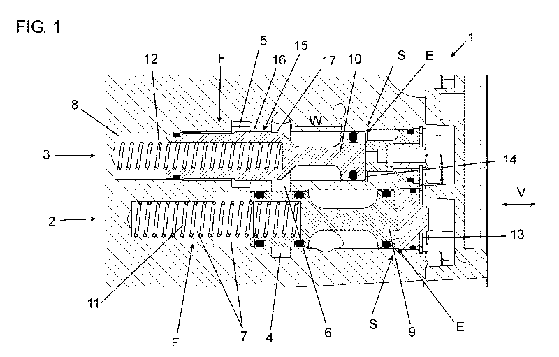
With a control valve assembly 1 portrayed in Fig. 1 for the indirect pneumatic
control of
the working pressure for a pneumatic vane motor of a hoist, a first and a
second valve
unit 2, 3 are arranged parallel to each other in a common housing.
Each of the two valve units 2, 3 is formed as a spring-biased pneumatically
operated
valve. Correspondingly, a movable valve piston 9, io is arranged in a valve
cylinder 7, 8
in each of the valve units 2, 3 such that a pressure fluid, in particular
compressed air,
guided through the valve unit 2, 3 can be blocked, or respectively regulated
by means of
a surface section of the valve cylinder 7, 8 and of the valve piston 9, 10.
On one side, the valve piston 9, io is biased by a spiral spring 11, 12 toward
a closed po-
sition, wherein one end of the spiral spring 11, 12 braces against a round
face of the
valve cylinder 7, 8, whereas the other end is secured within a hole in the
valve piston 9,
10. At the other end E of the valve piston 9, io, a control pressure chamber
13, 14 is
produced in the valve cylinder 7, 8. The control pressure chambers 13, 14 of
both valve
units 2, 3 are jointly connected to an inlet for a control pressure airflow so
that pressure
can build up in the control pressure chamber 13, 14 that counteracts the
spring tension
of the spiral spring 11, 12 and allows the valve piston 9, 10 to be moved by
applying the
control pressure to the face of the valve piston 9, 10.
Date Recue/Date Received 2020-07-21
CA 03089166 2020-07-21
- 11 -
The control valve unit 1 has a working pressure air inlet 4 as well as a
corresponding
outlet 5 that provides a pressure-controlled compressed air flow for the vane
motor of
the hoist. The outlet 5 is connected to the working pressure air inlet 4
through a work-
ing pressure air channel 6, wherein the working pressure air channel 6 runs
sequen-
tially through both valve units 2, 3 and can be blocked and regulated in each
case in a
blocking and control region 15 by means of the valve units 2, 3.
A valve surface 16, 17 is arranged on both the second valve piston io as well
as the asso-
ciated valve cylinder 8 that lie against each other when the valve unit 2, 3
is in a closed
state. Both valve surfaces 16, 17 are arranged at an angle to each other so
that when the
valve piston io moves in the valve cylinder 8, an enlarging valve opening
forms in the
shape of an annular gap as movement increases.
Fig. 1 shows a control valve assembly 1 with both valve units 2, 3 in the
closed position
so that the first valve unit 2 blocks the working pressure air flow just after
the working
pressure air inlet 4, and no pressure in the region of the working pressure
air channel 6
is applied to the second valve unit 3. In this state of the control valve
assembly 1, there
is also no control pressure, or respectively the control pressure of the
control pressure
air in the control pressure chambers 13, 14 lies below a fixed threshold value
of approxi-
mately 1.2 bar for opening the valve units 2, 3.
Fig. 3 shows a control valve assembly 1 in a state that only occurs briefly,
or respectively
exactly upon reaching a threshold value of the control pressure for opening
the valve
units 2, 3. The first valve unit 2 is completely open, whereas the second
valve unit 3 is
still closed. The control pressure in the first control air pressure chamber
13 counter-
acts the first spiral spring 11 enough to just open the valve opening of the
first valve unit
2 in that the two valve surfaces 16, 17 of the first valve unit 2 disengage.
As the control pressure increases, the second valve piston 10 of the second
valve unit 3
now is also moved against the spring force of the spiral spring 12 toward the
open posi-
tion, wherein the spring force is selected so that the valve piston io is
shifted over the
maximum adjustment path W within a predefined pressure range, preferably
between 1
bar and 6 bar.
Date Recue/Date Received 2020-07-21
CA 03089166 2020-07-21
- 12 -
In order to first of all enable a sensitive control and then a quick and
forceful release of
the working air pressure as the control pressure increases, the valve surfaces
16, 17 of
the second valve unit 3 are formed by a changing angle a, b within the control
surface 17
of the valve piston 10 (see Fig. 2). The valve surface 16 of the valve
cylinder 8 is pro-
duced as a linearly running cylindrical surface as part of the wall of the
valve cylinder 8.
The valve surface 17 of the valve piston io has two sections A, B at an angle
to each
other which are each also arranged at an angle a, b to the opposing valve
surface 16.
Both sections A, B have a linear contour. The angle a of the first section of
the valve sur-
face 17 to the opposing valve surface 16 is 50, whereas the corresponding
angle b of the
second section B is 450. The two sections A, B extend over 85% of the maximum
adjust-
ment path W of the valve piston 10 in the valve cylinder 8.
Fig. 4 shows a control valve assembly 1 with the first valve unit 2 in the
completely open
position and the second valve unit 3 in a partially open position, wherein the
working
pressure air is guided through an annular gap formed by the control surfaces
16, 17 of
the second valve unit 3, and a reduced volumetric flow through this annular
gap can
flow through the working pressure air channel 6 from the working air pressure
inlet 4
to the outlet 5 of the control valve assembly.
Finally, Fig. 5 shows a control valve assembly 1 with both valve units 2, 3 in
the com-
pletely open position, wherein the working pressure air can flow unhindered
through
the working pressure air channel 6 from the working air pressure inlet 4 to
the outlet 5
of the control valve assembly through the control surfaces 16, 17 of the two
valve units
2,3.
Date Recue/Date Received 2020-07-21
CA 03089166 2020-07-21
- 13 -
List of Reference Numbers
1 Control valve assembly
2 First valve unit
3 Second valve unit
4 Working fluid inlet
5 Outlet
6 Working fluid channel
7 First valve cylinder
8 Second valve cylinder
9 First valve piston
10 Second valve piston
ii First spring element
12 Second spring element
13 First control pressure chamber
14 Second control pressure chamber
15 Blocking and control region
16 First valve surface
17 Second valve surface
A First section
B Second section
E End of the valve piston
F Region of the spring element
S Region of the control pressure chamber
V Adjusting direction
W Maximum adjustment path
a Angle of the first section
b Angle of the second section
Date Recue/Date Received 2020-07-21