Note : Les descriptions sont présentées dans la langue officielle dans laquelle elles ont été soumises.
PERSONAL CARE TOOL FOR COOLING AND TREATING SKIN
FIELD OF THE INVENTION
The invention is in the field of personal care tools that provide a cooling
effect, and
are used to treat puffiness, inflammation and the appearance of the skin.
BACKGROUND OF THE INVENTION
Handheld cooling implements for drawing heat away from the surface of the skin
are
known. One type of device makes use of a removable reservoir of liquid coolant
that acts as
a heat sink to draw heat away from a skin-contact surface. The removal of heat
from the skin
surface provides a cooling effect. In those embodiments that use a reservoir
of coolant, the
reservoir must be removed from the device, chilled, and reinserted into the
device at the
time of use. Opportunities to damage or misplace the reservoir of coolant make
this type of
device less than ideal. A simpler, more reliable device would not use a
reservoir of liquid
coolant, and would not require a user to disassemble and reassemble the
device. Other
known devices may use a phase change material, a material that transitions
from solid to
liquid, as the heat sink to receive heat from the user's skin. However, since
the phase change
material is initially frozen, the tool incorporating the material is too cold
for personal care
facial applications.
SUMMARY
A personal care cooling tool according to the present invention provides a
cooling
sensation. Upon contact with a surface, the tool removes thermal energy from
the surface.
The tool may be used to treat areas of the face, such as under-eye, forehead,
cheeks, and
jowls to improve the appearance of the skin by reducing inflammation,
puffiness, blood
pooling and other undesirable skin imperfections. The tool may also be used to
massage
other parts of the body to sooth and relax the muscles, and reduce swelling in
cutaneous
tissues. In a laboratory environment, a personal care tool according to the
present may also
be used to lower the temperature of solid surfaces and fluid materials without
chemically
altering or diluting the constituents.
1
Date recue / Date received 2021-11-02
The cooling tool comprises an applicator head that has a relatively higher
thermal
conductivity, a grasping surface that has a relatively lower thermal
conductivity, and a heat
absorbing core that has a thermal capacity above a certain minimum value.
Preferably, these
components are permanently assembled so that from a user perspective, the tool
is a one-
piece construction, and does not need to be disassembled and reassembled by
the user.
This is unlike some cooling devices that require or have a removable reservoir
of coolant. In
those embodiments, the reservoir of coolant must be removed from the device,
chilled, and
reinserted into the device at the time of use. In contrast, the permanent
assembly described
herein is easier to use, and makes for a very robust hand tool that stands up
to consumer
usage and environmental factors that could lead to damage and diminished
functionality.
The tool can also be manufactured at a lower price point.
In accordance with an embodiment of the present invention the handheld cooling
tool
includes a hollow, elongated body that has a thermal conductivity less than
0.5 W/m-K. The
elongated body has a proximal end, an opened distal end, and a central
longitudinal axis. A
.. metallic applicator head is retained in and protrudes from the opened
distal end of the body.
The applicator head is a single piece and includes a skin contact surface that
has a roughness
between 0.4pm and 70pm, a slot, and a thermal conductivity greater than 10 W/m-
K. A
metallic heat absorbing core extends from the slot of the applicator head,
down into the
hollow body. The heat absorbing core has a thermal capacitance of at least 25
J/K and a mass
of 50g to 150g. The heat absorbing core contacts the body, wherein an air gap
separates the
heat absorbing core and the body, such that less than 1% of the surface of the
heat absorbing
core is in contact with the body.
DESCRIPTION OF THE FIGURES
Fig. 1 depicts a personal care tool (10) for cooling and treating skin
according to the present
invention.
Fig. 2 depicts a cross section of the tool (10) of Fig. 1.
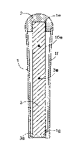
Figs. 3A, 3B and 3C depict the body (1) of the cooling tool (10).
Fig. 4 depicts the applicator head (2).
2
Date recue/ date received 2022-02-18
Fig. 5 depicts the connection of the applicator head (2) to the body (1).
Figs. 6, 7 and 8 depict various embodiments of the applicator head (2).
Fig. 9 depicts a cooling tool (10) reposed in a charging base (6).
Figs. 10, 11 and 12 show some common areas of the face where the cooling tool
(10) may be
applied for an expected benefit.
Figs. 13A and 13B show an embodiment of the invention with a control for
adjusting the rate
at which the cooling tool (10) cools the skin.
DETAILED DESCRIPTION
Referring to Figs. 1 and 2, a cooling tool (10) according to the present
invention
comprises a body (1) that supports an applicator head (2) and houses a heat
absorbing core
(3). The applicator head is thermally connected to the heat absorbing core. An
optional spring
(5) is provided between the applicator head and body. The construction of
these
20
30
2a
Date recue/ date received 2022-02-18
CA 03090245 2020-07-31
WO 2019/152635 PCT/US2019/016026
elements is intended to facilitate substantial heat transfer from the skin to
the core of the
tool in a short amount of time.
The Body
Referring to Figs. 3A, 3B and 3C, the body (1) is a hollow, elongated member
that
serves as a handle. The body has a proximal end (la) (that may be opened or
closed), an
opened distal end (lb), and a central longitudinal axis (1c). The body is
sized to be
comfortably grasped in the hand of a user. For example, a body may typically
be from 5 to 20
cm in length. The cross sectional shape of the body is preferably circular,
but may be some
other shape. The cross section will have largest dimension (a diameter, for
example) of
about 1 to 5 cm. The body supports the applicator head (2) and houses the heat
absorbing
core (3). To support the applicator head, the inner surface of the distal end
(1b) of the body
may be provided with a groove (1d; see detail section shown in Fig. 3C) that
interacts with
the applicator head as described below.
The body (1) is a relatively poor conductor of heat. This isolates the user's
hand from
the applicator head (2), so that the efficiency of the applicator head is not
compromised by
heat from the user's hand. Specifically, since the body is a poor conductor of
heat, the heat
that emanates from the hand of a user cannot easily pass through the body and
into the heat
absorbing core (3) or applicator head, which would decrease the efficiency of
the tool by
decreasing the heat transfer from the applicator head into the heat absorbing
core. Also, as
we will see, the body has minimal contact with the applicator head and the
heat absorbing
core, which further limits the movement of thermal energy. Preferably, the
body is
fashioned of plastic, such as varieties of polyethylene (PET, PETG, etc.), and
not metal. Also,
the body will have a low thermal conductivity, which we define as less than
about 0.5 Wjm-K,
to prevent heat transfer from the user's hand. For aesthetic reasons, the body
may be clear
or opaque.
Applicator Head
Referring to Fig. 4, the applicator head (2) comprises a skin contact surface
(2c). The
skin contact surface is that part of the cooling tool (10) that contacts the
skin of a user, to
draw heat away from the user's skin. The applicator head is connected to the
body (1) and
3
CA 03090245 2020-07-31
WO 2019/152635 PCT/US2019/016026
the heat absorbing core (3). The applicator head that is retained in the
opened distal end
(lb) of the body and protrudes from the distal end so that it may contact the
skin of a user.
There are various useful means for achieving the connection to the body. For
example, the
base (2a) of the applicator head may be sized to fit into the opened distal
end (lb) of the
body, and retained there by a snap fitting, or by a screw threaded engagement,
or by
adhesive (preferably an adhesive that does not conduct heat very well). The
snap fitting may
comprise an annular ring (2d) on the base of the applicator head that fits
snuggly into the
groove (1d) of the body. Since the body (1) is plastic, the opening at the
distal end (lb) of the
body will flex to enlarge slightly, and allow the annular ring of the
applicator head to slide
down into the groove. A slot (2b) is located in the applicator head, sized to
receive a distal
end (3b) of the heat absorbing core (3) (see Fig. 5). Optionally, a gasket (4)
may be situated
in between the applicator head and body to prevent water or other contaminants
from
getting into the body (see Fig. 4).
In some embodiments, the connection between the applicator head (2) and body
(1)
is rigid and permanent from a consumer-use perspective. This prevents a lose
connection
between the applicator head and body, which would lead to an inconsistent
experience for
the consumer. Optionally, however, a resilient component, such as a spring (5;
see Fig. 5),
may be disposed between the body (1) and the applicator head (2). In this
embodiment, the
applicator head, with the heat absorbing core attached (3), would be capable
of moving
between a first position and a second position relative to the body, while
still remaining
connected to the body. For example, in first position, an annular ring (2d')
on the base (2a)
of the applicator head contacts a stop (id') located on the inner surface of
the body (as
shown in Fig. 5). When a user presses the applicator head against her skin,
the applicator
head moves toward a second position. In second position, the annular ring
(2d') is below the
stop (1c1'). When the user removes the applicator head from her skin, the
spring expands to
return the applicator head to first position. The primary benefit of the
spring is to provide a
consistent application pressure between the skin and applicator head, as a
user moves the
tool around her face. By maintaining a consistent application pressure, the
heat transfer rate
from the skin to the applicator head has minimal variation, so that the tool
gives a more
consistent performance. The use of a sprung applicator head also provides a
softer tactile
experience for the user, which is more comfortable and more elegant.
4
CA 03090245 2020-07-31
WO 2019/152635 PCT/US2019/016026
The applicator head (2) must have a relatively high thermal capacity and be a
good
conductor of heat. This will allow for substantial heat transfer away from the
skin, and into
the heat absorbing core. The thermal conductivity of the applicator head must
be large,
which we define as greater than about 10 Winn-K. In general, the most
efficient applicator
head will be of unitary, of single construction. The preferred material for
the applicator head
is metal, which, through polishing, can be provided with a specified surface
finish. In general,
a smooth surface is not only more comfortable for the user, but provides the
most physical
contact between the skin and applicator head. In contrast, a rougher surface
would trap air
between the skin and applicator, which would decrease heat transfer, since air
is a relative
poor conductor of heat. However, there are other considerations, so that the
temperature at
which a user intends to use the tool should be considered when designing the
surface finish
of the applicator head. For example, at temperatures below the freezing point
of water
(such as might be found in a consumer freezer), a rougher surface texture is
preferred to
prevent the metal applicator head from sticking to the facial tissue. In this
case, a preferred
surface roughness is between 0.4unn and 70unn. While the rougher surface will
trap air
between the skin and applicator causing a decrease in heat transfer, the very
cold
temperature of the applicator head will more than make up for that. On the
other hand, for
warmer temperatures such as 5 C (as might be found in a consumer refrigerator)
up to room
temperature, a finer surface texture is preferred to maximize the heat
transfer rate, and to
provide the user with a comfortable experience. In this case, the preferred
surface
roughness is between 0.01211m and - 2.01.inn. Suitable materials for the
applicator head
include aluminum, brass, copper, cast iron, gold, silver, and steel. A
preferred metal is
stainless steel, which can accept a high degree of polishing and will resist
corrosion.
The shape of the skin contact surface (2c) will also determine how efficiently
heat is
transferred away from the skin. In general, the more contact between the skin
and the skin
contact surface, the more quickly heat will be drawn away from the skin, and
the
temperature of the skin will be lowered. However, consumer comfort is also a
factor, and
the ability to easily glide the applicator head over the skin. Thus,
applicator heads with sharp
angles and straight edges should be avoided, as these may scratch the skin, or
otherwise be
uncomfortable. Therefore, preferred skin contact surfaces are preferably
shaped as spherical
domes ranging from hemi-spherical (Fig. 6) to something less than hemi-
spherical Figs. 7 and
5
CA 03090245 2020-07-31
WO 2019/152635 PCT/US2019/016026
8). They have no sharp angles or straight edges. Note Fig. 8, where the
applicator head may
be positioned off center, that is, not symmetric with respect to the central
longitudinal axis
(1c) of the body (1). When the applicator is less than hemi-spherical, this
off center
positioning provides the user with a more comfortable angle at which to hold
the tool.
The domed applicator head (2) is characterized by a radius (2e) and an apex
(2f). In
general, the radius of the skin contact surface (2c) of the applicator head
typically ranges
from 0.5cnn to 30cnn. Ideally, an applicator head with a larger radius will be
used on the
forehead and cheekbones, and an applicator head with a smaller radius will be
used around
the eyes and nose. For example, in tests, a radius of between about 1.0cnn and
1.5cnn proved
useful for under eye treatment, while between 1.1cm and 1.2cm proved to be
ideal for under
eye treatment; small enough to work the tight areas near the canthus of the
eye, but large
enough to allow coverage of the area in just a few strokes. Even smaller radii
proved useful
for treating crow's feet where sustained targeted cooling is beneficial. A
radius between
about 1.0cnn and 2.0cm was very useful for a full-face application, while a
radius greater than
about 2.0cnn and up to 30cnn can be used to serve broad, flat areas of the
body, like the arms,
legs, bottoms of the feet, etc.
Heat Absorbing Core
The heat absorbing core (3) is a metallic mass having a distal end (3b) and a
proximal
end (3a). The distal end of the heat absorbing core is inserted into the slot
(2b) of the
applicator head (2), while the proximal end of the heat absorbing core extends
down into the
hollow body (1). The heat absorbing core is a heat sink, designed to
efficiently accept the
heat that is coming through the applicator head from that portion of a user's
skin that is
being treated, but not so efficiently from the hand of a user coming through
the body. The
heat absorbing core and the applicator head are both metallic. They may be
made of the
same metal (stainless steel, for example) or different metals. Either way, the
heat absorbing
core should have a higher thermal capacity than the applicator head, so that
heat is
continuously drawn away from the user's skin during the intended use of the
tool. Thermal
capacities of the applicator head and heat absorbing core are determined by
the respective
thermal capacitances of each member and the mass of each member. In general,
the mass of
the heat absorbing core is much larger than that of the applicator head, but
it is also
6
CA 03090245 2020-07-31
WO 2019/152635
PCT/US2019/016026
preferable if the thermal capacitance of the heat absorbing core is equal to
or greater than
the thermal capacitance of the applicator head. Most preferably, the thermal
capacitance of
the heat absorbing core is significantly greater than the thermal capacitance
of the applicator
head. By having both a greater mass and a greater thermal capacitance, the
heat absorbing
core will efficiently draw heat form the applicator head. In general, the heat
absorbing core
has a relatively high a thermal capacitance; at least 25 J/K and preferably
greater. Preferably,
the core extends almost the entire length of the interior of the body, which
allows the core
to be as large as possible, and therefore, a better heat sink. Preferably, the
mass of the core
is from about 40g to about 150g, more preferably, from 50g to 125g, and most
preferably
about 60g to 100g.
We can also speak of the thermal capacity of the combined applicator head and
heat
absorbing core. As a unit, a combined thermal capacity of about 25 to 35 J/K
has proven to
be very effective when the use time is 4 to 5 minutes for a tool charged in a
household
refrigerator.
In preferred embodiments, the distance from the applicator head to the center
of
mass (3e) of the heat absorbing core is as large as possible. This allows the
absorbed heat to
travel as far away from the applicator head as possible. Therefore, it is
preferable if the
distance from the applicator head to the center of mass (3e) of the heat
absorbing core is at
least one-third the of the length of the body (1).
The heat absorbing core (3) may be a cylindrical mass, the distal end (3b) of
which is
permanently inserted into the slot (2b) in the applicator head (2). The core
may be retained
in the slot of the applicator head by a friction fit, snap fit or threaded
engagement.
Alternatively, a heat conductive adhesive (1e) may be disposed between the
applicator head
and the heat absorbing core. When a heat conductive adhesive is used, it
should have a
thermal conductivity of at least 1 W/m-K, to ensure adequate overall heat
transfer rate.
Alternatively, the heat absorbing core and the applicator head may be
fashioned as a unitary
structure. Alternatively, in some embodiments to be discussed below, the heat
absorbing
core is moveable with respect to the applicator head, the distal end (3b) of
the heat
absorbing core being able to slide proximally and distally within the slot
(2b) of the applicator
head.
7
CA 03090245 2020-07-31
WO 2019/152635 PCT/US2019/016026
It is preferable if the heat absorbing core (3) has minimal contact with the
body (1) to
limit the amount of heat that is transferred from a user's hand, through the
body, and into
the core. Therefore, although the heat absorbing core extends the length of
the interior of
the body, an air gap (1f) separates the two. If it is necessary to add
additional support for the
heat absorbing core, then there may be minimal contact between the core and
the body.
Minimal contact means that less than 1% of the surface of the heat absorbing
core is in
contact with the body. For example, Figs. 2 and 3 show a spline or rib (1g)
located near the
proximal end (1a) of the body (1), to support the weight of the heat absorbing
core.
However, in this case, the amount of contact between the body and heat
absorbing core is
minimal (i.e. less than 1% of the heat absorbing core is in contact with the
body) and has no
detrimental effect on the use of the tool to cool the skin. In some
embodiments to be
discussed below, the distal end (3b) of the heat absorbing core is supported
in the slot (2b) of
the applicator head (2) by a spring (12).
The cooling tool (10) has an overall length that is measured from the apex
(2f) of the
skin contact surface (2c) of the applicator head (2) to the proximal end (1a)
of the body (1).
The cooling tool is significantly heavier than most cosmetic and personal care
implements.
Therefore, for optimal control by a user, the center of mass (10e) of the
cooling tool (10)
should be located a distance from the apex of the skin contact surface of the
applicator head
that is between 25% and 75% of the length of the tool, preferably between 25%
and 50% of
the length of the tool. For example, if the cooling tool is 10cnn long, then
the center of mass
will be between 2.5cm and 7.5cnn from the apex of the skin contact surface, or
more
preferably, between 2.5cm and 5.0 cm from the skin contact surface of the
applicator head.
Or, if the tool is 5cnn long, then the center of mass of the tool will be
between 1.25cnn and
3.75cm from the skin contact surface (2c) of the applicator head, or more
preferably,
between 1.25cnn and 2.5cm from the apex of the skin contact surface of the
applicator head.
Use
Generally, a personal care tool (10) for cooling and treating skin as
described herein,
should be chilled before use. Preferably, the tool will be placed in any
environment whose
ambient temperature is lower than about 15 C, and remain there long enough to
equilibrate.
More preferably, the ambient temperature is about 5 C - 10 C. Such
temperatures are
common in household refrigerators. A cooling tool for cooling and treating
skin as described
8
CA 03090245 2020-07-31
WO 2019/152635 PCT/US2019/016026
herein can also be stored in an environment having an ambient temperature
below 0 C, but
when the applicator head is that cold, it may be uncomfortable for some users.
Once the applicator head (2) is cooled, a user grasps the body (1) of the tool
(10) and
contacts the applicator head to the surface of her skin where treatment is
desired. This may
mean that the applicator head is drawn across the surface of the skin (as
depicted by paths
(8) and (9) in Figs. 11 and 12) or held on a single spot for a period of time
(as depicted by (7)
in Fig. 10) or a combination of the two. The cold applicator head removes heat
from the skin
surface, which pass through the applicator head, and into the heat absorbing
core. The
transfer of heat is fast, and the cooling effect can be maintained for a
significant period of
time, such as, at least 5 minutes, for example. During this time, the tool may
be used to treat
areas of the face, such as under-eye, forehead, cheeks, and jowls to improve
the appearance
of the skin by reducing inflammation, puffiness, blood pooling and other
undesirable skin
imperfections. The tool may also be used to massage other parts of the body to
sooth and
relax the muscles, and reduce swelling in cutaneous tissues.
In development of a personal care cooling tool, as claimed herein, the
inventors
repeatedly observed that the tool is effective to treat the skin by reducing
skin temperature,
and that the effect remains for a substantial period of time (more than 5
minutes) after the
treatment has ended. The cooling effect not only lasts longer than the cooling
effect of a
control group, but the magnitude of the effect is also greater than the effect
of the control
group. The observed effect was definitely attributable to the use of the
cooling tool as
claimed herein.
Optional Charging Base
As described above, prior to use, the personal care cooling tool is placed in
a cold
environment, and allowed to equilibrate to the ambient temperature. The length
of time for
this to happen can be shortened by the use of a charging base, as now
described. Referring
to Fig. 9, the charging base (6) comprises housing (6a) and a heat sink (6b).
In use, the
charging base will remain in a cold environment, like a refrigerator, so that
it is always ready
for use. The principle, here, is similar to how the heat absorbing core (3)
draws heat away
from the applicator head (2). Only now, the heat sink (6b) of the charging
base will draw
9
CA 03090245 2020-07-31
WO 2019/152635
PCT/US2019/016026
heat away from the heat absorbing core (3) of the cooling tool (10), which
allows the heat
absorbing core and the applicator head to cool more rapidly.
In the embodiment of Fig. 9, the charging base (6) comprises a plastic housing
(6a)
that houses the heat sink (6b), and into which the personal care cooling tool
(10) can be
reposed. The heat sink is a mass of metal, at least a portion (6c) of which
protrudes from the
plastic housing (6a) so that it can contact the proximal end (3a) of the heat
absorbing core (3)
of the cooling tool. In this embodiment, the proximal end (1a) of the body (1)
of the cooling
tool is opened, so that when the cooling tool is reposed in the charging base,
then the
protruding portion (6c) of the heat sink passes into the proximal end of the
body (1) and
makes physical contact with the heat absorbing core. It is the physical
contact between the
heat sink (6b) and the heat absorbing core (3) that forces the applicator head
to cool more
rapidly than if the tool is placed in a refrigerator without the charging
base. Preferably, the
heat sink has a thermal capacity that is at least as large as the thermal
capacity of the heat
absorbing core, although this is not strictly necessary to see a benefit.
Therefore, it is
preferable if the heat sink (6b) of the charging base has a thermal
capacitance of at least 25
J/K, and preferably greater, and a mass of 50g, and preferably greater.
Specifically, it is more
preferable if the heat sink (6b) has a thermal capacity that is at least twice
as large as the
thermal capacity of the heat absorbing core.
When a consumer wants to use the cooling tool, she opens her refrigerator,
removes
the tool from the charging base, leaving the charging base in the
refrigerator. After use, the
tool is returned to the charging base, in the refrigerator.
Optional Variable Cooling Rate Control
Optionally, some embodiments of the present invention may comprise a control
for
adjusting the rate at which the cooling tool cools the skin. The control
allows a user to move
the heat absorbing core with respect to the applicator head, thereby adjusting
the rate of
heat transfer from the applicator head to the heat absorbing core. The concept
is illustrated
in Figs. 13A and 13B. A first portion (11b) of a flexible enclosure (11) is
disposed in the slot
(2b) between the applicator head (2) and the distal end (3b) of the heat
absorbing core (3). A
second portion (11c) of the flexible enclosure is disposed between the heat
absorbing core
and the body (1). A fluid (11a) is disposed in the flexible enclosure (11). A
spring (12) is
CA 03090245 2020-07-31
WO 2019/152635 PCT/US2019/016026
disposed between the proximal end (3a) of the heat absorbing core and the
proximal end
(1a) of the body, such that the heat absorbing core is able to move
longitudinally as more or
less fluid is moved into or out of the slot (2b) of the applicator head.
As shown, a switch (13) passes through the wall of the body (1), and is able
to slide
longitudinally between a first position and a second position. When moved into
the first
position, the switch compresses the flexible enclosure (11), and when moved
toward second
position, the switch allows the flexible enclosure to relax. As the flexible
enclosure is
compressed by the switch, some of the fluid (11a) moves into the first portion
(11b) of a
flexible enclosure, which forces the heat absorbing core (3) to move
proximally, compressing
the spring (12). As a result, less of the distal end (3b) of the heat
absorbing core is in the slot
(2b) of the applicator head, and the rate of heat transfer from the applicator
head to the heat
absorbing core is decreased. Thus, the rate of cooling is decreased. This is
shown in Fig. 13B.
Likewise, as the switch moves from first position to second position, the
spring (12) expands
forcing the heat absorbing core to move distally (that is, further into the
slot of the applicator
head) and moving some of the fluid into the second portion (11c) of the
flexible enclosure.
As a result, the heat absorbing core more efficiently removes heat from the
applicator head.
Thus, the rate of cooling is increased. This is shown in Fig. 13A.
11