Sélection de la langue

Search

Sommaire du brevet 3090260 

Énoncé de désistement de responsabilité concernant l'information provenant de tiers

Une partie des informations de ce site Web a été fournie par des sources externes. Le gouvernement du Canada n'assume aucune responsabilité concernant la précision, l'actualité ou la fiabilité des informations fournies par les sources externes. Les utilisateurs qui désirent employer cette information devraient consulter directement la source des informations. Le contenu fourni par les sources externes n'est pas assujetti aux exigences sur les langues officielles, la protection des renseignements personnels et l'accessibilité.

Disponibilité de l'Abrégé et des Revendications

L'apparition de différences dans le texte et l'image des Revendications et de l'Abrégé dépend du moment auquel le document est publié. Les textes des Revendications et de l'Abrégé sont affichés :

  • lorsque la demande peut être examinée par le public;
  • lorsque le brevet est émis (délivrance).
(12) Demande de brevet: (11) CA 3090260
(54) Titre français: ELEMENT DE CONSTRUCTION ISOLE
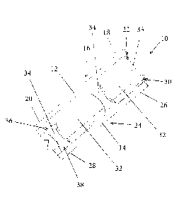
(54) Titre anglais: INSULATED CONSTRUCTION MEMBER
Statut: Demande conforme
Données bibliographiques
(51) Classification internationale des brevets (CIB):
  • E04C 02/296 (2006.01)
  • E04B 01/78 (2006.01)
  • E04C 03/29 (2006.01)
(72) Inventeurs :
  • FERGUSON, BRANDON (Canada)
(73) Titulaires :
  • BRANDON FERGUSON
(71) Demandeurs :
  • BRANDON FERGUSON (Canada)
(74) Agent: C6 PATENT GROUP INCORPORATED, OPERATING AS THE "CARBON PATENT GROUP"
(74) Co-agent:
(45) Délivré:
(22) Date de dépôt: 2020-08-17
(41) Mise à la disponibilité du public: 2022-02-17
Licence disponible: S.O.
Cédé au domaine public: S.O.
(25) Langue des documents déposés: Anglais

Traité de coopération en matière de brevets (PCT): Non

(30) Données de priorité de la demande: S.O.

Abrégés

Abrégé anglais


An insulated construction member has a first wooden rail and a second wooden
rail. The second wooden rail is positioned in parallel spaced relation to the
first wooden rail.
This parallel spaced relation creates a thermal break between the first wooden
rail and the
second wooden rail. A series of planar wooden connectors are positioned at
spaced intervals
along the length of the first wooden rail and the length of the second wooden
rail. Each of
the planar wooden connectors extends across the thermal break between the
first wooden rail
and the second wooden rail. A polymer insulation is positioned between the
first wooden
rail and the second wooden rail completely filling the thermal break. The
polymer insulation
encapsulates the series of planar wooden connectors, with the polymer
insulation being
reinforced by the series of planar wooden connectors.

Revendications

Note : Les revendications sont présentées dans la langue officielle dans laquelle elles ont été soumises.


What is Claimed is:
1. An insulated construction member, comprising:
a first wooden rail having a length, a first end, a second end and at least
one slot t ed
opening oriented longitudinally along the length;
a second wooden rail having a length, a first end, a second end and at least
one slotted
opening oriented longitudinally along the length, the second wooden rail being
positioned in
parallel spaced relation to the first wooden rail, the parallel spaced
relation creating a thermal
break between the first wooden rail and the second wooden rail;
a series of planar wooden connectors positioned at spaced intervals along the
length
of the first wooden rail and the length of the second wooden rail, each of the
planar wooden
connectors extending across the thermal break between the first wooden rail
and the second
wooden rail, each of the planar wooden connectors having a first edge and a
second edge
opposed to the first edge, with the first edge engaging the at least one
slotted opening in the
first wooden rail and the second edge engaging the at least one slotted
opening in the second
wooden rail; and
a polymer insulation is positioned between the first wooden rail and the
second
wooden rail completely filling the thermal break, the polymer insulation
encapsulating the
series of planar wooden connectors with the polymer insulation being
reinforced by the series
of planar wooden connectors.
2. The insulated construction member of Claim 1, wherein the at least one
slotted opening in
the first wooden rail is a single slotted opening that extends between the
first end and the
second end of the first wooden rail and wherein the at least one slotted
opening in the second
wooden rail is a single slotted opening that extends between the first end and
the second end
of the second wooden rail.
3. The insulated construction member of Claim 1, wherein each of the planar
wooden
connectors is an hourglass shape, which is wide at the first edge, wide at the
second edge, and
7

relatively narrow at in a middle portion.
4. The insulated construction member of Claim 3, wherein the middle portion
having
opposed side edges, each of the opposed side edges defming a concave radius.
5. The insulated construction member of Claim 1, wherein each of the planar
wooden
connectors is made from oriented strand board (0 SB).
6. The insulated construction member of Claim 1, wherein each of the planar
wooden
connectors is made from plywood.
7. An insulated construction member, comprising:
a first wooden rail having a length, a first end, a second end and a single
slotted
opening oriented longitudinally and extending along the entire length of the
first wooden rail
between the first end and the second end;
a second wooden rail having a length, a first end, a second end and a single
slotted
opening oriented longitudinally and extending along the entire length of the
second wooden
rail between the first end and the second end, the second wooden rail being
positioned in
parallel spaced relation to the first wooden rail, the parallel spaced
relation creating a thermal
break between the first wooden rail and the second wooden rail;
a series of planar wooden connectors positioned at spaced intervals along the
length
of the first wooden rail and the length of the second wooden rail, each of the
planar wooden
connectors extending across the thermal break between the first wooden rail
and the second
wooden rail, each of the planar wooden connectors having a first edge and a
second edge
opposed to the first edge, with the first edge engaging the at least one
slotted opening in the
first wooden rail and the second edge engaging the at least one slotted
opening in the second
wooden rail, each of the planar wooden connectors is an hourglass shape, which
is wide at
the first edge, wide at the second edge, and relatively narrow at in a middle
portion, the
middle portion having opposed side edges, with each of the opposed side edges
defining a
concave radius; and
8

a polymer insulation is positioned between the first wooden rail and the
second
wooden rail completely filling the thermal break, the polymer insulation
encapsulating the
series of planar wooden connectors with the polymer insulation being
reinforced by the series
of planar wooden connectors.
8. The insulated construction member of Claim 8, wherein each of the planar
wooden
connectors is made from oriented strand board (0 SB).
9. The insulated construction member of Claim 8, wherein each of the planar
wooden
connectors is made from plywood.
9

Description

Note : Les descriptions sont présentées dans la langue officielle dans laquelle elles ont été soumises.

TITLE
[0001] Insulated Construction Member
FIELD
[0002] There is described a construction member that is insulated to retard
thermal
transfer. This construction member was developed to serve as a wall stud, but
it is now
realized that the same principles can be applied in making top plates, bottom
plates, and other
construction members.
BACKGROUND
[0003] The concept of a wall stud with insulation to create a "thermal
break" has been
proposed in a number of existing patents, such as: U.S. Patent 8,516,778
(Wilkens) titled
"Insulated Wall Stud System"; U.S. Patent 9,103,113 (Lockhart) titled "Wall
Stud with a
Thermal Break"; and U.S. Patent 9,783,985 (Iverson) titled "Thermal Break Wood
Stud with
Rigid Insulation with Non-Metal Fasteners and Wall Framing System".
SUMMARY
[0004] There is provided an insulated construction member which has a
first wood en rail
and a second wooden rail. The first wooden rail has a length, a first end, a
second end and at
least one slotted opening oriented longitudinally along the length. The second
wooden rail
has a length, a first end, a second end and at least one slotted opening
oriented longitudinally
along the length. The second wooden rail is positioned in parallel spaced
relation to the first
wooden rail. This parallel spaced relation creates a thermal break between the
first wooden
rail and the second wooden rail. A series of planar wooden connectors are
positioned at
spaced intervals along the length of the first wooden rail and the length of
the second wooden
rail. Each of the planar wooden connectors extends across the thermal break
between the
first wooden rail and the second wooden rail. Each of the planar wooden
connectors has a
first edge and a second edge opposed to the first edge. The first edge engages
the at least one
slotted opening in the first wooden rail and the second edge engages the at
least one slotted
opening in the second wooden rail. A polymer insulation is positioned between
the first
wooden rail and the second wooden rail completely filling the thermal break.
The polymer
insulation encapsulates the series of planar wooden connectors with the
polymer insulation
1
Date Recue/Date Received 2020-08-17

being reinforced by the series of planar wooden connectors.
[0005] The insulated construction member, as described above, provides a
thermal break
between the first wooden rail and the second wooden rail which is filled with
insulation.
[0006] As described above, there is at least one slotted opening in the
first wooden rail
and at least one slotted opening in the second wooden rail. There could be a
series of discrete
slotted openings for each of the series of planar wooden connectors. However,
it is preferred
that there be a single slotted opening that extends between the first end and
the second end of
the first wooden rail and a single slotted opening that extends between the
first end and the
second end of the second wooden rail. Each of the planar wooden connectors
engages the
same single slotted opening in the first wooden rail and the same single
slotted opening in the
second wooden rail. The planar wooden connectors are bonded at spaced
intervals in the
single slotted opening in the first wooden rail and the single slotted opening
in the second
wooden rail with glue. The remainder of each single slotted opening provides
increased area
for the foam bond, with the result that the insulation is retained more
securely.
[0007] It is preferred that each of the planar wooden connectors is an
hourglass shape,
which is wide at the first edge, wide at the second edge, and relatively
narrow at in a middle
portion. The planar wooden connectors are wider at the first edge where
connection is made
with the first rail and at the second edge where the connection is made with
the second rail.
This wider connection point reduces twisting. The relatively narrower middle
portion leaves
more room for insulation and less area for thermal transfer along the planar
wooden
connector.
[0008] The middle portion of the planar wooden connectors has opposed
side edges. It is
preferred that each of the opposed side edges define a concave radius to
minimize stress
concentration at the middle portion.
[0009] The preferred materials for making the planar wooden connectors is
either
2
Date Recue/Date Received 2020-08-17

oriented strand board (OSB) or plywood. It will be appreciated that there may
be other
similar or substitute materials that could be used.
BRIEF DESCRIPTION OF THE DRAWINGS
[0010] These and other features will become more apparent from the
following
description in which reference is made to the appended drawings, the drawings
are for the
purpose of illustration only and are not intended to be in any way limiting,
wherein:
[0011] FIG. 1 is a perspective view of an insulated construction member.
[0012] FIG. 2 is a side elevation view of the insulated construction
member of FIG. 1,
with polymer foam insulation removed.
[0013] FIG. 3 is an exploded side elevation view of the insulated
construction member of
FIG. 3.
DETAILED DESCRIPTION
[0014] An insulated construction member generally identified by reference
numeral 10,
will now be described with reference to FIG. 1 through FIG. 3.
Structure and Relationship of Parts:
[0015] Referring to FIG. 2, insulated construction member 10 includes a
first wooden
rail 12 and a second wooden rail 14. First wooden rail 12 has a length 16, a
first end 18, a
second end 20 and a single slotted opening 22 oriented longitudinally and
extending along
the entire length of first wooden rail 12 between first end 18 and second end
20. Second
wooden rail 14 has a length 24, a first end 26, a second end 28 and a single
slotted opening
oriented longitudinally and extending along the entire length of second wooden
rail 12
25 __ between first end 26 and second end 28. Although not illustrated,
alternatively, single slotted
opening 22 and single slotted opening 30 could be a series of discrete slotted
openings.
Second wooden rail 14 is positioned in parallel spaced relation to first
wooden rail 12, the
parallel spaced relation creating a thermal break 32 between first wooden rail
12 and second
wooden rail 14.
3
Date Recue/Date Received 2020-08-17

[0016]
Referring to FIG. 2, a series of planar wooden connectors 34 are positioned at
spaced intervals along the length of first wooden rail 12 and the length of
second wooden rail
14. Each planar wooden connector 34 is extending across thermal break 32
between first
wooden rail 12 and second wooden rail 14. Referring to FIG. 3, each planar
wooden
connector 34 has a first edge 36 and a second edge 38 opposed to first edge
36. As illustrated,
first edge 36 and second edge 38 are straight edges. Referring to FIG. 2,
first edge 36 is
engaging single slotted opening 22 in first wooden rail 12 and second edge 38
is engaging
single slotted opening 30 in second wooden rail 14. Referring to FIG. 3, each
planar wood en
connector 34 has an hourglass shape, which is wide at first edge 36, wide at
second edge 38,
and relatively nan-ow at in a middle portion 40. Middle portion 40 has opposed
side edges 42,
with each opposed side edge 42 defining a concave radius. It is to be noted
that at first end 18
of first wooden rail 12 and first end 26 of second wooden rail 14, end planar
wooden
connector 35 is rectangular in shape, with each opposed side edge 43 being
straight edges. It
is to be noted that at second end 20 of first wooden rail 12 and second end 28
of second
wooden rail 14, end planar wooden connector 35 is rectangular in shape, with
each opposed
side edge 43 being straight edges. The reason for this is ensure that the ends
are planar for
finishing and connection. The studs have to be connected to top plates and
bottom plates
when framing a wall. Insulation will not hold nails. Having wood at the ends
can be
important when nailing the insulated construction member, especially when "toe
nailing" is
used.
[0017]
Referring to FIG. 1, a polymer insulation 44 is filling thermal break 32
between
first wooden rail 12 and second wooden rail 14. Polymer insulation 44 is
encapsulating the
series of planar wooden connectors 34 and being reinforced by the series of
planar wooden
connectors 34.
[0018] Each
of the planar wooden connectors 34 is made from oriented strand board
(0 SB ) or made from plywood.
Advantages:
[0019] In
addition to the "obvious" advantages of reducing weight and improving
4
Date Recue/Date Received 2020-08-17

thermal characteristics, there are a number of further advantages that the
above described
structure with the planar wooden connectors 34 provides that are worthy of
noting:
[0020]
Planar wooden connectors 34 maintain spacing between first rail 12 and second
.. rail 14.
[0021]
Planar wooden connectors 34 distribute loads between first rail 12 and second
rail
14.
[0022] The hourglass shape of planar wooden connectors 34 serves an
important purpose.
Planar wooden connectors 34 are wider at first edge 36, where connection is
made with first
rail 12, and at second edge 38, where the connection is made with second rail
14. This wider
connection point reduces twisting. The narrower middle portion 40 leaves more
room for
insulation and less area for thermal transfer along the planar wooden
connector. Middle
portion 40 of planar wooden connectors 34 has opposed side edges 42. It is
preferred that
each of the opposed side edges 42 define a concave radius to minimize stress
concentration at
middle portion 40.
[0023] The
series of planar wooden connectors 34 maintains spacing of first rail 12 and
second rail 14 for polymer foam insulation application, allow for greater
amounts of foam
insulation over and between planar wooden connectors 34 and, once planar
wooden
connectors 34 are encapsulated in the insulation, planar wooden connectors 34
serve to
reinforce the insulation.
[0024] In this patent document, the word "comprising" is used in its non-
limiting sense to
mean that items following the word are included, but items not specifically
mentioned are not
excluded. A reference to an element by the indefinite article "a" does not
exclude the
possibility that more than one of the element is present, unless the context
clearly requires
that there be one and only one of the elements.
5
Date Recue/Date Received 2020-08-17

[0025] The scope
of the claims should not be limited by the illustrated embodiments set
forth as examples, but should be given the broadest interpretation consistent
with a purposive
construction of the claims in view of the description as a whole.
6
Date Recue/Date Received 2020-08-17

Dessin représentatif
Une figure unique qui représente un dessin illustrant l'invention.
États administratifs

2024-08-01 : Dans le cadre de la transition vers les Brevets de nouvelle génération (BNG), la base de données sur les brevets canadiens (BDBC) contient désormais un Historique d'événement plus détaillé, qui reproduit le Journal des événements de notre nouvelle solution interne.

Veuillez noter que les événements débutant par « Inactive : » se réfèrent à des événements qui ne sont plus utilisés dans notre nouvelle solution interne.

Pour une meilleure compréhension de l'état de la demande ou brevet qui figure sur cette page, la rubrique Mise en garde , et les descriptions de Brevet , Historique d'événement , Taxes périodiques et Historique des paiements devraient être consultées.

Historique d'événement

Description Date
Inactive : Lettre officielle 2024-03-28
Inactive : Lettre officielle 2023-08-15
Demande visant la révocation de la nomination d'un agent 2023-07-25
Demande visant la nomination d'un agent 2023-07-25
Exigences relatives à la révocation de la nomination d'un agent - jugée conforme 2023-07-25
Exigences relatives à la nomination d'un agent - jugée conforme 2023-07-25
Exigences quant à la conformité - jugées remplies 2022-09-09
Demande publiée (accessible au public) 2022-02-17
Inactive : Page couverture publiée 2022-02-16
Demande visant la révocation de la nomination d'un agent 2022-01-12
Demande visant la nomination d'un agent 2022-01-12
Exigences relatives à la nomination d'un agent - jugée conforme 2022-01-12
Exigences relatives à la révocation de la nomination d'un agent - jugée conforme 2022-01-12
Inactive : CIB en 1re position 2020-11-15
Inactive : CIB attribuée 2020-11-15
Exigences de dépôt - jugé conforme 2020-08-28
Lettre envoyée 2020-08-28
Demande reçue - nationale ordinaire 2020-08-17
Inactive : Pré-classement 2020-08-17
Déclaration du statut de petite entité jugée conforme 2020-08-17
Inactive : CQ images - Numérisation 2020-08-17
Représentant commun nommé 2020-08-17

Historique d'abandonnement

Il n'y a pas d'historique d'abandonnement

Taxes périodiques

Le dernier paiement a été reçu le 2023-07-25

Avis : Si le paiement en totalité n'a pas été reçu au plus tard à la date indiquée, une taxe supplémentaire peut être imposée, soit une des taxes suivantes :

  • taxe de rétablissement ;
  • taxe pour paiement en souffrance ; ou
  • taxe additionnelle pour le renversement d'une péremption réputée.

Les taxes sur les brevets sont ajustées au 1er janvier de chaque année. Les montants ci-dessus sont les montants actuels s'ils sont reçus au plus tard le 31 décembre de l'année en cours.
Veuillez vous référer à la page web des taxes sur les brevets de l'OPIC pour voir tous les montants actuels des taxes.

Historique des taxes

Type de taxes Anniversaire Échéance Date payée
Taxe pour le dépôt - petite 2020-08-17 2020-08-17
TM (demande, 2e anniv.) - petite 02 2022-08-17 2022-08-16
TM (demande, 3e anniv.) - petite 03 2023-08-17 2023-07-25
Titulaires au dossier

Les titulaires actuels et antérieures au dossier sont affichés en ordre alphabétique.

Titulaires actuels au dossier
BRANDON FERGUSON
Titulaires antérieures au dossier
S.O.
Les propriétaires antérieurs qui ne figurent pas dans la liste des « Propriétaires au dossier » apparaîtront dans d'autres documents au dossier.
Documents

Pour visionner les fichiers sélectionnés, entrer le code reCAPTCHA :


Pour visualiser une image, cliquer sur un lien dans la colonne description du document. Pour télécharger l'image (les images), cliquer l'une ou plusieurs cases à cocher dans la première colonne et ensuite cliquer sur le bouton "Télécharger sélection en format PDF (archive Zip)" ou le bouton "Télécharger sélection (en un fichier PDF fusionné)".

Liste des documents de brevet publiés et non publiés sur la BDBC .

Si vous avez des difficultés à accéder au contenu, veuillez communiquer avec le Centre de services à la clientèle au 1-866-997-1936, ou envoyer un courriel au Centre de service à la clientèle de l'OPIC.


Description du
Document 
Date
(aaaa-mm-jj) 
Nombre de pages   Taille de l'image (Ko) 
Dessins 2020-08-16 3 90
Description 2020-08-16 6 242
Revendications 2020-08-16 3 107
Abrégé 2020-08-16 1 22
Dessin représentatif 2022-01-16 1 12
Courtoisie - Lettre du bureau 2024-03-27 2 190
Courtoisie - Certificat de dépôt 2020-08-27 1 575
Paiement de taxe périodique 2023-07-24 1 26
Changement de nomination d'agent 2023-07-24 6 249
Courtoisie - Lettre du bureau 2023-08-14 2 198
Courtoisie - Lettre du bureau 2023-08-14 2 214
Nouvelle demande 2020-08-16 5 137
Paiement de taxe périodique 2022-08-15 1 26