Note : Les descriptions sont présentées dans la langue officielle dans laquelle elles ont été soumises.
CA 03090284 2020-07-31
WO 2019/156951 PCT/US2019/016596
DEVICES, METHODS, AND SYSTEMS FOR THE TREATMENT AND/OR MONITORING OF
DAMAGED TISSUE
[0001] This application claims the benefit of US Provisional Application
entitled DEVICE, METHODS,
AND SYSTEM FOR THE TREATMENT OF WOUNDS, Ser. No. 62/627,028, filed on February
6,
2018, which is incorporated by reference it its entirety herein.
FIELD OF THE INVENTION
[0002] This disclosure relates to devices, methods, and systems for the
treatment of wounds.
BACKGROUND OF THE INVENTION
[0003] Diabetic foot ulcers (DFUs) are the cause of over 80,000 amputations
each year in the
United States. The number of people who lose a limb due to diabetes is
expected to triple by the
year 2050. Nationally, of the over $100 billion spent annually on managing
diabetes, at least 33%
is linked to the treatment of DFUs.
[0004] Often, poor-healing, neuropathic wounds that occur on diabetic
patients, especially on the
lower extremities, will only worsen if left untreated, in part due to
impairment of blood flow.
Patients who have diabetes experience reduced blood flow in the limbs, and
ulcers often develop
on the bottom of the foot.
[0005] There is, therefore, a need for treatment and/or monitoring of DFUs
in a cost-effective
manner that can prevent amputation.
SUMMARY OF THE INVENTION
[0006] Embodiments of the disclosure comprise devices, methods, and systems
for the
treatment and/or monitoring of damaged tissue, such as wounds. The devices,
methods, and
systems may be embodied in a variety of ways, and may provide the ability for
electrical
stimulation and heat treatment in at-home setting.
[0007] Accordingly, a therapeutic device is disclosed for treating damaged
tissue. The device may
include a heating component, which is configured to apply heat to a limb, and
a plurality of electrodes,
with at least one electrode configured to supply electrical stimulation, also
to the limb.
[0008] In one aspect, the device may further include a plurality of
sensors. Optionally, at least one
sensor is configured to measure at least one indicator of wound healing.
[0009] In other embodiments, the device may also comprise a pulse generator
being electrically
coupled with the plurality of electrodes, wherein the pulse generator is
configured to generate a
plurality of electrical impulses for delivering electrical stimulation
treatment to subject through at least
one electrode.
[0010] The device may also comprise at least one control unit to operate
the electrical pulse
stimulation and the heating component. The device may, in certain embodiments,
further comprise a
1
CA 03090284 2020-07-31
WO 2019/156951 PCT/US2019/016596
processor, wherein the processor comprises processing logic and telemetry to
determine a treatment
regimen for increasing blood flow based on carry-over effects.
[0011] In another embodiment, the device may include one or more sensors to
sense one or more
physiological conditions of a person undergoing treatment. For example, the
sensors may sense at
least one indicator of wound healing.
[0012] Optionally, the method may include generating electrical pulses and
applying the electrical
pulses to the limb to generate electrical stimulation.
[0013] In other aspects, the method includes processing logic and telemetry
to determine a
treatment regimen for increasing, optionally maximizing, a wearers blood flow
based on carry-over
effects.
[0014] In yet other aspects, the method includes collecting, and optionally
recording, stimulation data
and indicators of wound healing during treatment and after treatment.
In any of the above, suitable indicators may include physiologic, such as
bioimpedance, pH, heat in
the wound and lower extremity, periwound status measurements.
[0015] The method may further include enabling, disabling, and/or altering
the electrical stimulation
and/or heat based on the indicators. The method may additionally include
determining future
treatment parameters based on the indicators.
[0016] In yet another aspect, a system is disclosed that includes a
processing device; and a non-
transitory computer-readable medium communicatively coupled to the processing
device, wherein the
processing device is configured to perform operations comprising: receiving a
data set associated with
patient indicators of wound healing and stimulation data; storing the data
set; generating treatment
parameters based on the stored data set by determining a relationship between
initial treatment
parameters and plurality of the indicators of wound healing and the
stimulation data; and
electronically converting the stored data set into the next parameters based
on the relationship. In
certain embodiments, the system may further include a component for generating
an interface for
display that includes at least some of the data of the data set, which is
associated with the indicators
of wound healing and the stimulation data.
[0017] In another aspect, a method of treating damaged tissue is disclosed.
The method may
comprise the steps of applying heat and electrical simulation to or adjacent
the damaged tissue.
[0018] In one aspect, the method includes applying heat and electrical
simulation to at least a portion
of the limb with the damaged tissue. Further, applying the heat includes
applying the heat to at least
40%, or at least 50%, or at least 60%, or at least 70%, or at least 80%, or at
least 90%, or about 100%
of the portion ofthe limb to effect global warming of the limb.
2
CA 03090284 2020-07-31
WO 2019/156951 PCT/US2019/016596
[0019] In a further aspect, the method applying heat and electrical
simulation to the limb with the
damaged tissue. Further, applying the heat includes applying the heat to at
least 40%, or at least
50%, or at least 60%, or at least 70%, or at least 80%, or at least 90%, or
about 100% of the limb to
effect global warming of the limb.
[0020] In one embodiment, the method applying heat and electrical
simulation to the limb includes
applying the heat to at least 40% of the limb.
[0021] In another aspect, the method includes identifying tissue to be
treated; and placing a
therapeutic device with a heating component and a plurality of electrodes on
the limb, wherein the
device surrounds and/or covers a significant portion of the limb; and applying
heat to the limb and
while simultaneously conducting an electrical current through the plurality of
electrodes to apply
electrical stimulation to the limb.
[0022] The method may further include selecting a treatment protocol.
[0023] In some embodiments, the method may include covering at least 90%,
or at least 80%, or at
least 70%, or at least 60%, or at least 50%, or at least 40%, or at least 20%
of the limb.
[0024] In some embodiments, the method further includes sensing one or more
physiological
conditions of a person undergoing treatment. For example, the sensing may
include sensing at least
one indicator of wound healing. Additionally, the method may further include
measuring the
physiological condition, such as the indicator of wound healing.
[0025] Optionally, the method may include generating electrical pulses and
applying the electrical
pulses to the limb to generate electrical pulse.
[0026] In other aspects, the method includes processing logic and telemetry
to determine a
treatment regimen for increasing, optionally maximizing, wearers blood flow
based on carry-over
effects.
[0027] In yet other aspects, the method includes collecting, and optionally
recording, stimulation data
and indicators of wound healing during treatment and after treatment.
In any of the above, suitable indicators may include physiological and
bioimpedance measurements.
[0028] The method may further include enabling, disabling, and/or altering
the electrical stimulation
and/or heat based on the indicators. The method may additionally include
determining future
treatment parameters based on the indicators.
[0029] In yet another aspect, a system is disclosed that includes a
processing device; and a non-
transitory computer-readable medium communicatively coupled to the processing
device, wherein the
processing device is configured to perform operations comprising: receiving a
data set associated with
patient indicators of wound healing and stimulation data; storing the data
set; generating treatment
parameters based on the stored data set by determining a relationship between
initial treatment
3
CA 03090284 2020-07-31
WO 2019/156951 PCT/US2019/016596
parameters and plurality of the indicators of wound healing and the
stimulation data; and
electronically converting the stored data set into the next parameters based
on the relationship. In
certain embodiments, the system may further include a component for generating
an interface for
display that includes at least some of the data of the data set, which is
associated with the indicators
of wound healing and the stimulation data.
[0030] Before the various embodiments disclosed herein are explained in
detail, it is to be understood
that the claims are not to be limited to the details of operation or to the
details of construction and the
arrangement of the components set forth in the following description or
illustrated in the drawings. The
embodiments described herein are capable of being practiced or being carried
out in alternative ways not
expressly disclosed herein. Also, it is to be understood that the phraseology
and terminology used herein
are for the purpose of description and should not be regarded as limiting. The
use of "including" and
"comprising" and variations thereof is meant to encompass the items listed
thereafter and equivalents
thereof as well as additional items and equivalents thereof. Further,
enumeration may be used in the
description of various embodiments. Unless otherwise expressly stated, the use
of enumeration should
not be construed as limiting the claims to any specific order or number of
components. Nor should the use
of enumeration be construed as excluding from the scope of the claims any
additional steps or
components that might be combined with or into the enumerated steps or
components.
BRIEF DESCRIPTION OF THE FIGURES
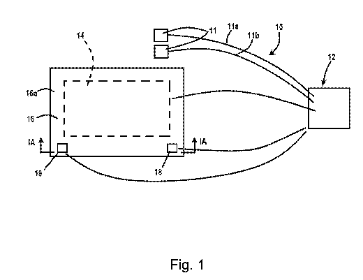
[0031] FIGURE 1 is a schematic diagram illustrating one embodiment of a
device for healing and/or
monitoring damaged tissue;
[0032] FIGURE 1A is cross-section taken along line IA-IA of FIGURE 1;
[0033] FIGURE 1B is a schematic drawing of an electrode with a sensor
integrated or co-located with
the electrode;
[0034] FIGURE 1C is a schematic diagram illustrating another embodiment of
the device for wound
healing in accordance, which is capable of guiding electrode placement around
a wound or a distal
nerve, applying electrical stimulation, applying heat, and/or monitoring blood
flow to control the
treatment endpoint;
[0035] FIGURE 2 is a schematic cross-section of the device of FIGURE 1A;
[0036] FIGURE 2A is a side by side image of a thermal map (left (39.7 Cat
crosshair)) of a
prototype and an image of the prototype (right);
[0037] FIGURE 3 shows a data display of a healthy human subject with 15 mA
of electric stimulation
in accordance with an embodiment of the disclosure (blood flow (top), skin
temp (middle), and
stimulation waveform (bottom));
4
CA 03090284 2020-07-31
WO 2019/156951 PCT/US2019/016596
[0038] FIGURE 4 shows supporting data from human subjects wearing the
device in accordance
with an embodiment of the methods (blood flow (blood perfusion units (BPU),
black) doubles as
temperature ( C, gray) increases);
[0039] FIGURE 5 shows a block diagram illustrating a control unit in
accordance with an embodiment
of the disclosure;
[0040] FIGURE 6 shows a flow chart illustrating the decision tree based on
physiologic measurement
feedback in accordance with an embodiment of the disclosure; and
[0041] FIGURE 7 shows an experimental setup used to acquire supporting data
in accordance with
an embodiment of the disclosure.
DETAILED DESCRIPTION
[0042] As will be more fully described below, disclosed herein are devices,
methods, and systems for
treating and/or monitoring damaged tissue, including treating and/or
monitoring ulcers, such as
diabetic ulcers. The disclosed devices, methods, and systems may reduce the
risk of wound
infection, treat infection, and/or promote healing of damaged tissue, such as
wounds, via the joint
application of heat and electrical stimulation. The devices, methods, and
systems may be embodied
in a variety of ways. Further, although described in reference to a human or
person, it should be
understood that the devices, methods, and systems disclosed herein may also be
used on animals.
[0043] Referring to Figure 1, the numeral 10 generally designates a device
for treating and/or monitoring
damaged tissue, such as a wound. Device 10 includes at least two or more
electrodes 11 for attaching
to a person's limb at or near the damaged skin to apply electrical stimulation
to the underlying tissue,
including muscles, nerves, and optionally tendons. For example, electrodes 11
may include self-
adhesive electrodes, including self-adhesive rubber electrodes, or taped-on
electrodes. Optionally,
the electrodes may comprises dry fabric electrodes from conductive thread or
carbon electrodes for MRI
compatibility.
[0044] Alternately, the electrodes 11 may be applied to a location remote
from the damaged skin, for
example, over a muscle or nerve that extends into the limb. See below
discussion of additional
embodiments for further discussions of suitable locations for the electrodes.
[0045] Device 10 also includes a control unit 12, which is powered by a
battery or other source of
current/voltage (such as a standard 120-volts wall outlet) and is in
electrical communication with
electrodes 11 via electrical leads 11a, 11 b (FIGURE 1) and configured to
supply electrical current to
at least one of the electrodes. Accordingly, depending on the type of current
(AC/DC) and/or voltage
provided or delivered to control unit 12, control unit 12 may include a
converter (AC to DC or DC to
AC) and a transformer to adjust (such as reduce or increase where applicable)
the supplied voltage
CA 03090284 2020-07-31
WO 2019/156951 PCT/US2019/016596
and one or more resistors to adjust (e.g. reduce) the current to suitable
levels, described more fully
below.
[0046] Optionally, control unit 12 includes a controller and a pulse
generator, which is electrically
coupled to the controller and to the source of electricity (either directly or
through the controller via
electrical leads), which can generate a plurality of electrical impulses for
delivering an electrical pulse
wave form to the at least one electrode for applying to the person's skin or
tissue, to thereby
administer the electrical pulse stimulation treatment through electrodes 11.
Depending on where and
how much current is applied, and where the electrodes are placed, the
electrical stimulation may
induce neuromuscular stimulation (NMES) or transcutaneous stimulation (TENS)
or microtens (MCT)
stimulation. Optionally, the pulse generator generates a biphasic pulse wave
form, for example, a
symmetric biphasic wave form. Again, for further discussion of suitable wave
forms, reference is
made to the description that follows.
[0047] Control unit 12 may be constructed of an electrical component, or
group of electrical components,
which are capable of carrying out the functions described herein. As noted,
control unit 12 may include a
controller, such as a conventional microcontroller or group of conventional
microcontrollers. In general, the
controller includes any one or more microprocessors, field programmable gate
arrays, systems on a chip,
volatile or nonvolatile memory, discrete circuitry, and/or other hardware,
software, or firmware that is
capable of carrying out the functions described herein, as would be known to
one of ordinary skill in the art.
Such components can be physically configured in any suitable manner, such as
by mounting them to one
or more circuit boards, or arranging them in other manners, whether combined
into a single unit or
distributed across multiple units. When implemented to communicate with a
remote device, including a
server, a phone, a pad, or other hand held electronic device, the control unit
12 may include a
communication device, such as a Bluetooth device, a WiFi device, or a micro
USB, which can provide a
communication interface with the remote device.
[0048] Where device 10 is configured for use in a home setting, the pulse
generator may generate a
biphasic pulse wave form with an amplitude in a range of 1-50 mA
(milliamperes), or 10-40 mA, or 15-
35 mA, and optionally about 20 mA depending on the desired stimulation. The
pulse width may be in
a range of 10-1000 ps (micro seconds), 50-800 ps, 300-500 ps, again depending
on the desired
stimulation. For example, for smaller muscles, a suitable amplitude may be
around 30 mA and a
pulse width may fall in a range of 50-200 ps. For example, for larger muscles,
a suitable amplitude
may be around 50 mA and a suitable pulse width may fall in a range of 300-500
ps. For nerves, a
suitable amplitude may be around 20 mA and a suitable pulse width may fall in
a range of 20-100 ps.
It should be understood that these are exemplary only, and that the amplitude
in milliamps and pulse
width varies not only on the type of tissue but the habitus of the tissue
being stimulated. The principles fall
6
CA 03090284 2020-07-31
WO 2019/156951 PCT/US2019/016596
under the concept of the strength-duration curve. As a result, the amplitude
of the current can vary
based on the person and/or type of tissue to be stimulated and/or the type of
tissue damage that is
being treated and/or location of treatment. Further, as noted, the electrical
current may be an AC
current or DC current, and in some settings a high volt direct current (HVDC).
[0049] When configured for use in a medically supervised setting, these
values may be adjusted.
For example, in medically supervised setting, the pulse generator may generate
a biphasic pulse
wave form with an amplitude in a range of 0.25 mA to 100 mA, 10 mA to 75 mA,
or optionally about
20 mA depending on the desired stimulation. The pulse width may be in a range
of 50 to 500ps, 100
to 300p5, or optionally about 250 ps, again depending on the desired
stimulation. For example, for
smaller muscles, a suitable amplitude may be around 20 mA and a pulse width
may be around 250
ps. For larger muscles, a suitable amplitude may be around 30mA and a suitable
pulse width may be
about 300 ps. For nerves, a suitable amplitude may be around 20mA and a
suitable pulse width may
fall in a range of 20-100 ps.
[0050] Optionally, in addition to electrical stimulation, electrodes 11 may
be used to warm the tissue and,
therefore, form a heating component. In order to achieve a warming effect, the
pulse generator may
generates a pulsed radio-frequency range in the range of 50 - 500 kHz, with an
amplitude in the
range of 1 to 100 V or 50 to 100V, and a duty cycle 1% to 100% (pulsed-to-
continuous on-time).
This could help to heat deep into the limb, especially if you place the
electrodes on opposite sides.
Further, the pulse generator may be adjustable and configured (e.g. by control
unit 12) to switch
between an electrical stimulation modality and a warming modality where
different wave forms are
desired for each desired effect.
[0051] Optionally, in lieu of or in addition to warming using electrodes
11, device 10 may include a
separate heating component 14, which may be controlled by control unit 12.
Heating component 14 may
be in the form of an electric heating coil, an electronic heater, such as a
Peltier device or infrared LEDS, or
heated fluid (such as water that flows though channels or tubing), or chemical
warmers that when bent or
pressed start a chemical exothermic reaction. The heating component 14 is
further configured so that it
"globally" heats the limb (or portion of the limb) that includes the damaged
tissue. The term "global" or
"globally" refers to raising the temperature of the limb (or portion of the
limb) and not just local warming of
the limb where the limb surface and the tissue beneath the surface are warmed.
To achieve global
warming, heat is applied about 40%-100% of the limb or body part (or portion
of the limb or body part),
and optionally to at least at least 40%, or at least 50%, or at least 60%, or
at least 80%, or at least
90%, or about 100%.
[0052] In one embodiment, globally warming the limb is achieved by wrapping
the heating
component 14 around the limb (or portion of the limb) so that it covers at
least 20%, or at least 30%,
7
CA 03090284 2020-07-31
WO 2019/156951 PCT/US2019/016596
or at least 40%, or at least 50%, or at least 60%, or at least 70%, or at
least 80%, or at least 90%, or
about 100% of the limb or body part (or portion of the limb or body part). To
that end, heating
component 14 may be mounted (including encasing it) in a covering 16 that is
suitable for wrapping
around the limb being treated. The covering may be in the form of a large
patch of material or
materials, including fabric, which may be assembled from multiples layers
(e.g. 16a, 16b, and 16c),
with the separate heating component sandwiched between two of the layers, and
the layer 16a
touching the person's skin being formed from a material that is comfortable to
the touch. Optionally,
two or more layers may be joined together to form a bladder for inflating the
covering or for forming a
conduit(s) through which warming fluid may be circulated to form the heating
component.
[0053] Additionally, as described below, the patch may include a layer of
thermally conductive
material, for example, to transfer the heat to a greater area than the
footprint of the heating
component and/or a layer of thermally reflective material, either or both of
which may increase the
efficiency of the heat transfer from the heating component to the limb or body
part. Optionally,
electrodes 11 may be integrated into or simply be co-located with the covering
16 (e.g. placed under
covering 16 on skin, but not necessarily attached to the covering).
[0054] To provide an efficient transfer of heat from the heating component
14 to the person's skin,
heating component 14 is located adjacent layer 16a, which is placed on the
person's skin. Optionally,
as noted, to increase the efficiency, one or more of the layers (e.g. layer
16b) may form a thermally
conductive and/or reflective layer to form an insulation layer, and may be
formed from a heat
reflective material, such as heat reflective thin plastic (such as a foil or a
thin plastic sheet coated with
a metallic reflecting agent, such as metallized polyethylene (MPET)). To
protect the various layers
and/or provide cushioning, layer 16c may comprise a protective outer layer,
such as a foam, including
neoprene. Alternately or in addition, as noted above and described below, one
of the layers may be a
thermally conductive layer to transfer the heat from the heating component
across the limb¨either to
provide a more uniform distribution of the heat and/or to facilitate transfer
of the heat beyond the
immediate "footprint" of the heating component.
[0055] Additionally, the patch of fabric may be shaped to conform to the
person's limb. For example,
as described in reference to the embodiments described below, the covering or
patch may be
configured into the shape of a boot, covering the lower portion of a leg. For
example, the covering
may start at the knee and extend to and optionally enclose the foot, for
example, in the case of
treating ulcers on the heel of a person. Or the patch may be configured as a
sleeve to cover an arm
and/or shoulder, or other body part. For additional or alternate details of
the various layers of material
that can be assembled to form covering 16 and to encase the heating component,
reference is made
to FIGURE 3 and the corresponding description.
8
CA 03090284 2020-07-31
WO 2019/156951 PCT/US2019/016596
[0056] In another embodiment, described more fully in reference to the
additional embodiments
below, device 10 may include one or more sensors 18 in communication
(electrical or wireless) with
control unit 12. Similar to electrodes 11, sensors 18 may be separately
mounted from the covering
16, co-located with covering 16, or integrated with covering 16. For example,
similar to electrodes 11,
sensors 18 may be located at the surface of layer 16a, for example, by surface
mounting or flush
mounting them to or in layer 16a (FIGURE 1A). When separately mounted or co-
located with
covering 16, sensors 18 may be mounted to the skin of the person using an
adhesive strip or an
adhesive, including an adhesive with a very low pull force required for
removable, such as a
conductive adhesive gel, including HYDROGEL, which is tacky enough to hold a
small device, such
as a sensor, in place, especially when then covered by covering 16, but is
easily removed to avoid
damage to the person's skin.
[0057] Further, the sensor or sensors 18 may be co-located with and/or
integrated with the electrode. For
example, referring to FIGURE 1B, the electrodes 11 may have an annular or
donut shape with central
opening (or a non-circular shape with an opening). The sensor, such as an
optical sensor, including a
blood flow sensor (e.g., IR LED + photodiode), can then be optionally co-
located in the central opening of
the electrode so that, for example, the electrode may hold the sensor in
place. Further, it may be
integrated into the electrode by commonly mounting the sensor with the
electrode on a shared substrate
on which both the sensor and electrode are mounted.
[0058] The sensors may be used to sense and, optionally, measure one or
more physiological
conditions of a person undergoing treatment and forward sensor signals to the
microprocessor of the
control unit 12, containing measurement data, for processing. In some
embodiments, the data from
the sensor signals may be sent to a remote location, for example, for
monitoring the wound, which is
more fully described below.
[0059] For example, the sensing may include sensing at least one condition
that is an indicator of
healing, such as wound healing, or the status of the damaged tissue, such as
the wound, including
whether there is an infection present. In one embodiment, sensors 18 may
monitor stimulation data
and indicators of wound healing during treatment and/or after treatment. Such
indicators may be
physiological, such as bioimpedance measurements, blood flow, blood flow
volume, pH of the wound,
temperature of the wound, temperature of the limb, sensor of periwound region
for abnormal moisture or
exudate. For example, control unit 12 may be configured to adjust the applied
heat based on the
sensor readings from the temperature sensor(s) and optionally provide closed
loop feedback control
of the heating component to avoid over heating or to increase the heat when
the temperature is too
low.
9
CA 03090284 2020-07-31
WO 2019/156951 PCT/US2019/016596
[0060] Suitable blood flow/blood volume sensors include
photoplethysmography (PPG)-blood flow
sensors and pulse oximeter sensors, which use two frequencies of light (red
and infrared) to determine the
percentage (%) of hemoglobin in the blood that is saturated vvith oxygen. The
percentage is
called blood oxygen saturation, or 402, which can be used to compute blood
volume.
[0061] Suitable infections sensors include sensors to detect pH, including
the use of in wound-pH strips,
which change color in response to the pH levels; electro-chemical bio sensors;
temperature sensors to
detect wound temperature, including the use of in-wound temperature strips; or
sensors that detect
myeloperoxidase, including myeloperoxidase responsive materials; which change
color in response to
elevated myeloperoxidase levels. In any of the above noted visual indicators,
electrical sensors (e.g.,
optical sensors) may then be used to detect the visual changes in the
indicators, which can then be
transmitted to the control unit 12.
[0062] Suitable sensors, as noted, include optical sensors ( e.g. light
sources combined with
photodiodes to measure reflectance or absorption of the light in the tissue,
for example to measure
oxygen) and Doppler probes to measure blood flow; blood flow volume (BVP)
sensor or
photoplethysmography to measure blood flow volume; Hall Effect sensors or
probes to monitor the
stimulation current delivered to the skin; temperature sensors, such as skin
temperature probes, to
measure temperature; pH sensors; moisture sensors; or a voltage sensor, such
as a differential high
voltage probe, to measure the applied voltage to the skin or tissue.
[0063] To detect infection, sensors 18 may comprise: a pH sensor (e.g.
measures activity of
hydrogen ions in the tissue or blood) to measure the pH of the skin, with a
low pH correlating to an
oncoming infection; a temperature sensor to measure the temperature of the
skin (as noted above),
with an increase in heat being used to indicate an infection; and/or a
moisture sensor, with an
increase in moisture correlating to an infection. The sensor may detect
moisture balance in and
around the wound to help prevent maceration of the periwound area. A suitable
moisture sensor
includes an electro-chemical bio sensor.
[0064] Accordingly, when an infection is detected or suspected, control
unit 12 may be configured to
stop operation of device 10 and, further, optionally generate a signal either
locally (e.g. an alarm
signal that generates a visual or audible notification) or remotely via a
communication device
(described above and below) to notify a third party, such as a nurse or doctor
of the apparent
infection.
[0065] In one embodiment, device 10 may switch between a treatment mode and
a monitoring mode or
device 10 may operate the modes together. For example, the monitoring mode may
operate during
pauses or temporal spaces between the pulsing of the electrical stimulation
(so as not to interfere with the
measurement) or between treatment phases. In one embodiment, control unit 12
may have a filter so that
CA 03090284 2020-07-31
WO 2019/156951 PCT/US2019/016596
the two modes can operate simultaneously, to filter out the signals generated
by the treatment when
reading and processing the monitoring signals.
[0066] In any of the embodiments, device 10 may include a pressure sensor
to detect the pressure and/or
any shear applied to the wound. For example, control unit 12 may be configured
to adjust treatment (e.g.
reduce or stop the applied heat and/or inflation of the covering in the case
of an inflatable covering) to off
load pressure from the wound based on the readings of the pressure sensor to
avoid constricting the body
part, such as the foot or leg.
[0067] In any of the embodiments, device 10 may include a user input
device, such as a switch or a
button, for example on a touch screen, to allow a caregiver (either locally or
remotely) or the user to turn off
the therapy functions and allow the device to simple monitor the damage
tissue, as noted above. The
user input device may alternately or in addition allow a caregiver, as noted
above, to select between
therapy protocols or adjust the therapy protocols.
[0068] In another embodiment of device, device 10 may be configured as a
monitoring device only,
thereby eliminating the need for a heating component and/or electrodes.
[0069] Control unit 12 then may be configured to control the pulse
generator (or current delivered to
the pulse generator) to control the delivery of electrical stimulation
provided by electrodes based on
the sensor signals. As noted above, it may be configured to stop the treatment
or may adjust the
treatment based on input from a caregiver and/or based the sensor readings. To
that end, the
controller of control unit 12 optionally includes processing logic to
determine a treatment regimen for
increasing, optionally optimizing, such as by maximizing, the wearers blood
flow. For example,
control unit 12 may stop or adjust one or more characteristics of the
electrical stimulation, such as the
wave form, including amplitude, duration, and pulse width based on input
(sensor signals or user
input). In this manner, control unit 12 can provide a closed loop feedback
control of the treatment
and/or monitoring of device 10.
[0070] In yet other aspects, control unit 12 may collect, and optionally
record, stimulation data and
indicators of wound healing during treatment and after treatment, which can be
available for upload or
download from control unit or, as noted above, transmitted to a remote
location.
[0071] In another embodiment, control unit 12 may simply have a preset mode
or program for
operating the electrodes 11 and/or heating element 14. For example, control
unit 12 may simply turn
on the treatment device (based on input from a caregiver or user) and power
the electrodes 11 and/or
heating component for a preselected time period with a preselected electrical
stimulation wave form
and/or temperature, and hence include a timer. Alternately, control unit 12
may be configured with
preset treatment protocol programs (e.g. stored in the memory of the control
unit), which can then be
11
CA 03090284 2020-07-31
WO 2019/156951 PCT/US2019/016596
either selected, using a user interface (such as buttons or a touch screen as
noted) or using a remote
device.
[0072] In one aspect, a therapeutic device is disclosed for treating
damaged tissue comprising a
heating component; wherein heat can be applied to a limb. In another
embodiment, the therapeutic
device includes a plurality of electrodes, wherein at least one electrode
supplies electrical pulse
stimulation. The therapeutic device, in some embodiments, further includes a
plurality of sensors,
wherein at least one sensor is configured to measure indicators of wound
healing. In another
embodiment, a pulse generator is electrically coupled with the plurality of
electrodes, wherein the
pulse generator is configured to generate a plurality of electrical impulses
for delivering electrical
stimulation treatment to a subject through at least one electrode. The
therapeutic device for treating
damaged tissue in some embodiments, includes at least one control unit to
operate the electrical
pulse stimulation and the heating component. In other embodiments, the
therapeutic device includes
a processor, wherein the processor includes processing logic and telemetry to
determine the optimal
treatment regimen for maximizing blood flow based on carry-over effects (that
is when the effect of
the treatment continues after the treatment is stopped).
[0073] In a second aspect, disclosed is a method of treating damaged tissue
comprising the steps of:
identifying tissue to be treated; placing a therapeutic device; selecting a
treatment protocol; applying
heat to a limb comprising the identified tissue; simultaneously conducting an
electrical current through
the plurality of electrodes; using a plurality of sensors to record
stimulation data and indicators of
wound healing during treatment and after treatment, wherein the indicators are
physiological, such as
bioimpedance, pH, heat and periwound measurements; enabling, disabling, and
altering the electrical
stimulation and heat based on the recorded indicators; and determining future
treatment parameters
based on the recorded indicators.
[0074] In a third aspect, this invention includes a system for treating
damaged tissue comprising a
processing device. In one embodiment, a non-transitory computer-readable
medium communicatively
coupled to the processing device, wherein the processing device is configured
to perform operations.
In some embodiments, the operations of the system include: receiving a data
set associated with
patient indicators of wound healing and stimulation data; storing the data
set; generating treatment
parameters based on the stored data by determining a relationship between
initial treatment
parameters and plurality of the indicators of wound healing and the
stimulation data; electronically
converting the stored data into the next parameters based on the relationship;
and generating an
interface for display that includes data associated with the indicators of
wound healing and the
stimulation data.
12
CA 03090284 2020-07-31
WO 2019/156951 PCT/US2019/016596
[0075] Each of the embodiments of the disclosed devices, methods, and
systems allow for the rapid
healing of damage tissue, such as wounds. For example, the disclosed devices,
methods, and
systems can promote healing of ulcers, such as diabetic foot ulcers (DFUs), in
a shortened time
period with superior results.
[0076] In some embodiments, the invention can be used to treat damaged
cells including, but is not
limited to ulcerated tissue. In addition to ulcers ( such as DFUs), this
device can be used to treat other
damage tissue, such as arthritic tissue, tendonitis, tendon or ligament
damage, muscle soreness, joint
pain, varicose veins, obesity, and peripheral artery disease.
[0077] Additionally, the device can promote the healing of xenograft,
allograft, autograft, or
engineered tissue following reconstruction surgery. Wounds that can be treated
by the present
invention include, but are not limited to non-healing or chronic wounds. In
some embodiments a
wound that does not improve after at least 3, 4, or 5 weeks or does not heal
after at least 7, 8, or 9
weeks are non-healing wounds. Non-healing wounds include, but are not limited
to DFUs, venous-
related ulcerations, non-healing surgical wounds, pressure ulcers, wounds
related to metabolic
disease, and wounds that repeatedly break down. Non-healing wounds place
patients at an increased
risk for infections. Often, poor-healing, neuropathic wounds that occur on
diabetic patients, especially
on the lower extremities, will only worsen if left untreated. Patients who
have diabetes experience
reduced blood flow and nervous activity in the limbs, and ulcers often begin
in high pressure areas,
such as on the bottom of the foot.
DEVICE FOR THE TREATMENT OF DAMAGED TISSUE
[0078] In one embodiment, a therapeutic device for treating damaged tissue
includes: a heating
component; wherein heat can be applied to a limb; a plurality of electrodes,
wherein at least one
electrode supplies electrical pulse stimulation; a plurality of sensors,
wherein at least one sensor is
configured to measure indicators of wound healing; a pulse generator being
electrically coupled with
the plurality of electrodes, wherein the pulse generator is configured to
generate a plurality of
electrical impulses for delivering electrical stimulation treatment to a
subject through at least one
electrode; at least one control unit to operate the electrical pulse
stimulation and the heating
component; and a processor, wherein the processor includes processing logic
and telemetry to
determine the optimal treatment regimen for maximizing blood flow based on
carry-over effects.
[0079] In some embodiments, the heating component is a flexible internal
heating coil. The
therapeutic device, in some embodiments includes a plurality of layers
comprising a heating
component layer having a first side and second side; an inner layer comprising
a plurality of dissimilar
materials, wherein the inner layer contacts the subject's skin; an outer layer
comprising a plurality of
dissimilar materials; and a discontinuous adhesive layer which affixes the
first side of the heating layer
13
CA 03090284 2020-07-31
WO 2019/156951 PCT/US2019/016596
to the inner layer and the second side of the heating component layer to the
outer layer. In some
embodiments, the inner layer includes two or more sublayers.
[0080] Also in some embodiments, a first sublayer is an inner insulative
sublayer, wherein the inner
insulative sublayer is an absorbent polymer. In further embodiments, the
insulative sublayer contacts
the subject's skin. The inner insulative sublayer, in some embodiments,
includes at least one of
fleece, wool, cotton, nylon, polyester, or a combination thereof. The inner
insulative sublayer can be
coated with an anti-microbial material. In further embodiments, a second
sublayer is an inner
conductive sublayer, wherein the inner conductive sublayer is an organic
polymer. The organic
polymer may include at least one of polyethylene terephthalate (PET),
metallized polyethylene
terephthalate (MPET), or biaxially oriented PET(BoPET).
[0081] In another embodiment, the skin contacting layer may comprise a
thermally conductive gel,
including a thermally conductive gel adhesive, such as HYRDROGEL.
[0082] The inner layer may uniformly distribute heat over the whole limb or
sections thereof. In
further embodiments, the thickness of the inner layer may be from 1-50 mm, or
from 2-25 mm, or from
5-10 mm.
[0083] Also in some embodiments, the outer layer includes two or more
sublayers. A first outer
sublayer may include a plastic mesh layer, wherein, the plastic mesh layer
contacts the second side
of the heating component layer. A second outer sublayer may include a
synthetic rubber. In some
embodiments, the synthetic rubber includes at least one of neoprene,
polyurethane, or nitrile rubber.
Also in further embodiments, the thickness of the outer layer may be from 1-50
mm, or from 2-25 mm,
or from 5-10 mm.
[0084] Sensors may be used to measure indicators of wound healing. The
plurality of sensors in
some embodiments, include at least one of Doppler probes, Hall Effect probes,
skin temperature
probes, or a differential high voltage probe.
[0085] In some embodiments, the therapeutic device includes at least one
control unit to operate the
electrical pulse stimulation and the heating component. Also in some
embodiments, the at least one
control unit includes a thermostat for selecting an amount of energy to
maintain the tissue
temperature.
[0086] Figure 10 illustrates an embodiment of a device 101 for treating
damaged tissue using a
thermo-regulated electrical stimulation. The therapeutic device may include a
control unit 112 that
controls a pulse generator, which can generate a plurality of electrical
impulses for delivering the
electrical pulse stimulation treatment to a subject through a plurality of
electrodes 111. The device
may further include a limb heating system 110, which globally applies heat to
a limb that contains
damaged tissue to be treated. In some embodiments, the electrodes 111 are
placed on a skin surface
14
CA 03090284 2020-07-31
WO 2019/156951 PCT/US2019/016596
in a general region of interest. The general region of interest may be a
critical nerve and/or blood
vessel. A wireless blood flow monitor 113 can be used to record physiologic
measurements.
[0087] In some aspects, the invention may include a device for applying
heat to the limb or a portion
thereof. In some embodiments, heat is applied to the whole-limb. The whole-
limb may be either a leg
or an arm. In other embodiments, heat is applied to at least one section of
the limb. The leg is
composed of five distinct sections: upper leg, knee, lower leg, ankle and
foot. The upper leg begins at
the hip and continues down to the knee. The knee is a pivot-like hinge joint
in the leg that connect the
upper and lower leg. The lower leg begins at the knee and continues down to
the ankle. The ankle
connects the lower leg to the foot. In some embodiments, heat is applied to
the lower leg-ankle-foot
complex. In still other embodiments, heat is applied to at least the distal
one-third of the lower limb,
but is preferably applied to at least the distal two-thirds of the lower limb.
As used here, distal means
further away from the heart and proximal means closer to the heart. In other
embodiments, the device
may be used to treat wounds on the trunk of the body.
[0088] In some embodiments, the heating component is a flexible internal
heating coil. A flexible
heating component will generally allow the heating component to conform to a
three-dimensional object. In some embodiments, the three-dimensional object
may be a whole-limb or
a portion thereof. In other embodiments, the flexible heating component may be
a wearable garment,
such as a boot, a sleeve for a shoulder, an elbow, or other body part.
[0089] In some embodiments, the heating component is internal to the
device. In some
embodiments, the heating component is removable. A removable heating component
can be inserted
into an opening between the inner and the outer layers. In other embodiments,
the heating
component will be fused into a single unit. In alternate embodiments, the
thickness of the heating
component layer may be from 1-20 mm, or from 1-10 mm, or from 1-5 mm.
[0090] In some embodiments, the heating component is run with a variable
voltage supply. In
alternate embodiments, the variable voltage supply may be from 1-120 V or from
1-24 V. A dry-cell
battery can be used to generate heat by means of an electric current. In some
embodiments, the
battery will have a voltage capacity of 12 V.
[0091] In some embodiments, the device includes a plurality of layers
comprising: a heating
component layer having a first side and second side; an inner insulative layer
comprising a plurality of
dissimilar materials, wherein the inner insulative layer contacts the
subject's skin; and an outer
insulative layer comprising a plurality of dissimilar materials; and a
discontinuous adhesive layer
which affixes the first side of the heating layer to the inner layer and the
second side of the heating
layer to the outer layer. In some embodiments, an inner insulative layer
includes two or more
CA 03090284 2020-07-31
WO 2019/156951 PCT/US2019/016596
sublayers. In some embodiments, the first inner insulative sublayer is an
absorbent polymer, wherein
the first inner insulative sublayer contacts the subject's skin.
[0092] The first insulative sublayer may be a woven material, a non-woven
material, or a fleece. In
some embodiments, the inner insulative sublayer includes at least one of
fleece, wool, cotton, nylon,
polyester, or a combination thereof. In some embodiments, the insulating
fabric can include a
synthetic fleece. The synthetic fleece may be a nonwoven fabric made from
polyester. In such an
embodiment, the fleece may have a density between 50-500 g/m2 or thickness may
be from 1-20
mm, or from 1-10 mm or from 1-5 mm. In some embodiments, the first layer is
fabricated so as to
adhere poorly to wounds. In such embodiments, poor adhesion allows the device
to be easily
removed from the wound, enabling treatment with limited to no pain to the
patient.
[0093] In some embodiments, an inner conductive sublayer is an organic
polymer. In some
embodiments, the organic polymer includes at least one of polyethylene
terephthalate (PET),
metallized polyethylene terephthalate (MPET), or biaxially oriented (BoPET,
i.e., MYLAR10). PET is a
thermoplastic polymer resin of the polyester family. PET can be spun into
fibers for permanent-press
fabrics, blow-molded, or extruded. MPET is a polymer film coated with a thin
layer of metal. In some
embodiments, the metal is aluminum. BoPET is a polyester film made from
stretched PET. In other
embodiments, an inner conductive sublayer may be graphite, copper, and
silicon, and carbonaceous
nanomaterials.
[0094] In some embodiments, the inner conductive sublayer is NASA foil.
NASA foil is a MPET.
NASA foil is a vacuum-metallized insulating material. NASA foil is designed to
be lightweight, and
may be made by depositing vaporized aluminum onto thin plastic substrates. The
result is a thin,
flexible material that provides superior thermal-reflective properties. The
flexible nature of NASA foil
allows it to conform to three-dimensional objects. In some embodiments, the
three-dimensional object
may be a whole-limb or portion thereof. In some embodiments, the three-
dimensional object may be a
wearable garment (e.g., a boot). In some embodiments, the thickness of the
inner conductive
layer is from 1- 20 mm, or from 1-10 mm, or from 1-5 mm. In aspects of the
invention, the inner layer
uniformly distributes heat over the whole limb. NASA foil is ideal for equally
distributing and retaining
heat on treated areas of skin due to its superior thermal-reflective
properties. In some instances,
NASA foil is meant to conserve heat as a passive warming system and is able to
stop both
evaporative and connective heat loss.
[0095] In some embodiments, the outer layer includes two or more sublayers.
In some embodiments,
the first outer sublayer is a plastic mesh layer, wherein, the plastic mesh
layer contacts the second
side of the heating component layer. In some embodiments, the second outer
sublayer is a synthetic
16
CA 03090284 2020-07-31
WO 2019/156951 PCT/US2019/016596
rubber. Synthetic rubbers have elastic properties that allow them to conform
to a three-dimensional
object. Such elasticity is ideal as it allows the device achieve optimal
contact with the area of skin to
be treated. In some embodiments, the synthetic rubber includes at least one of
neoprene,
polyurethane, or nitrile rubber. In some embodiments, the thickness of the
outer layer is from 1-20
mm, or from 1-10 mm, or from 1-5 mm.
Figure 2 illustrates an embodiment of the invention wherein the medical device
includes Slayers. The
inner insulative sublayer is fleece 210 with a thickness of 0.5 cm. The inner
conductive sublayer is
NASA foil 211 with a thickness of 0.5 cm. The first outer insulative sublayer
is plastic mesh 213 with a
thickness 0f2.0 cm. The second outer sublayer is neoprene 214 with a thickness
of 1.0 cm. An
internal heating coil 212 is inserted in between the inner conductive sublayer
211 and the first outer
sublayer 213.
[0096] Sensors may be used to measure indicators of wound healing. In
various embodiments, the
plurality of sensors include at least one of Doppler probes, Hall Effect
probes, skin temperature
probes, and a differential high voltage probe. Doppler probes are capable of
measuring blood flow. In
some embodiments, a wide-band Hall Effect sensor is used to monitor current.
Skin temperature
probes are capable of monitoring the temperature of the skin at treated sites.
Differential high voltage
probes can record voltage in real-time.
[0097] The therapeutic device for treating damaged tissue in some
embodiments includes at least
one control unit to operate the electrical pulse stimulation and the heating
component. In some
embodiments the at least one control unit includes a thermostat for selecting
an amount of energy to
maintain the tissue temperature. A thermostat comprising a temperature control
switch or button can
be used in connection with a temperature control element of the heating
component.
[0098] In further embodiments, the therapeutic device includes a processor,
wherein the processor
includes processing logic and telemetry to determine the optimal treatment
regimen for maximizing
blood flow based on carry-over effects.
METHODS FOR THE TREATMENT OF DAMAGED TISSUE
[0099] In another embodiment provided is a method of treating damaged
tissue. The method may
include the steps of identifying tissue to be treated; placing a therapeutic
device on or around a limb
encompassing the wound; selecting a treatment protocol; and applying heat and
electrical stimulation
to the limb and/or wound. The device may, in various embodiments include: a
heating component;
wherein heat can be applied to a limb; a plurality of electrodes, wherein at
least one electrode
supplies electrical pulse stimulation. The device may include a plurality of
sensors, wherein at least
one sensor is configured to measure indicators of wound healing. The device
may also include a
pulse generator being electrically coupled with the plurality of electrodes,
wherein the pulse generator
17
CA 03090284 2020-07-31
WO 2019/156951 PCT/US2019/016596
is configured to generate a plurality of electrical impulses for delivering
electrical stimulation treatment
to a subject through at least one electrode. The device may also include or be
in communication with
at least one control unit to operate the electrical pulse stimulation and the
heating component; and a
processor, wherein the processor includes processing logic and telemetry to
determine the optimal
treatment regimen for maximizing blood flow based on carry-over effects. In
some embodiments,
communication between at least one control unity and the device may be
wireless. For example, the
stimulation circuitry may be located within the device with an external
trigger located within a control
unit, wherein the control unit communicates wirelessly with the stimulation
circuitry within the device.
In certain embodiments, the method may include the steps of simultaneously
conducting an electrical
current through the plurality of electrodes; using a plurality of sensors to
record stimulation data and
indicators of wound healing during treatment and after treatment, wherein the
indicators are
physiologic and bioimpedance measurements. The method may include enabling,
disabling, and
altering the electrical stimulation and heat based on the recorded indicators;
and determining future
treatment parameters based on the recorded indicators. As discussed herein for
devices, the
methods may be applied to a whole limb or part of a limb.
[0100] Also disclosed herein are methods for treating damaged tissue
wherein the device is placed
around a limb. In some embodiments, the limb is a leg. In further embodiments,
the device is placed
around a leg or one or more sections thereof. Also disclosed herein are
methods wherein the at least
one control unit includes a thermostat for selecting an amount of energy to
maintain the tissue
temperature. The heating component may generate an amount of energy, which has
been
predetermined to maintain the tissue temperature from 45- 3000 or from 40- 35
C.
[0101] In some embodiments of the methods, the electrodes include two or
more electrical
conductors. The electrodes may be placed on a skin surface in a general region
of interest. The
general region of interest may include a critical nerve or blood vessel. In
other embodiments, the
general region of interest may include the area surrounding a critical nerve
or blood vessel. Critical
nerves, when stimulated, may assist with vasodilation of blood vessels thus
increasing blood flow.
Also in some embodiments, the critical nerve may be a vasoconstrictor nerve.
In further
embodiments, the vasoconstrictor nerve may be a sciatic nerve. In other
embodiments, the nerve is a
tibial or peroneal nerve. In other embodiments, the blood vessel is a femoral
artery. In other
embodiments, the general region of interest may be a wound. In some
embodiments, electrodes may
be placed to bracket the wound (e.g. placed on either side of wound).
[0102] Other aspects of the invention include methods for treating damaged
tissue wherein a test
pulse is delivered to determine the baseline electrical impedance of the
tissue and ensure proper
connectivity of the electrodes. The electrical pulses may be applied in an
amount, which has been
18
CA 03090284 2020-07-31
WO 2019/156951 PCT/US2019/016596
predetermined to cause vasodilation of blood vessels, wherein the electrical
pulses may be applied for
a pulse duration ranging from 1-5000 ps, or from 2-1,000 ps, or from 5-500 ps,
or from 10-50 ps. In
some embodiments, the electric pulses may have a voltage ranging from 0.1-500
V, or from 5-250 V,
or from 50-100 V. In some embodiments, the electrical pulses may have a
current amplitude ranging
from 1-500 mA, or from 5-250 mA, or from 50-100 mA. In another embodiment, the
electric pulses
may have a voltage ranging from 0.1 to 200 V, or from 50 to100 V, or from 0.1
to 50 V. In some
embodiments, the electrical pulses may have a current amplitude ranging from 1-
500 mA, or from 5-
250 mA, or from 50-100 mA.
[0103] In other embodiments of the methods, the electrical pulses may be
applied in an amount,
which has been predetermined to cause nerve stimulation by using comparatively
longer pulses or
pulses of greater strength. In some embodiments, the electrical pulses may be
applied for a duration
ranging from 1-10000 ps, or from 2-5000 ps, or from 50-1000 ps, or from 100-
500 ps. In some
embodiments, the electric pulses may have a voltage ranging from 1-1500 V, or
from 50-1000 V, or
from 200-500 V. In another embodiment, the electric pulses may have a voltage
ranging from 0.1-200
V, or from 0.1 to 50 V, or from 50-100 V. In some embodiments, the electrical
pulses may have a
current amplitude ranging from 1-1500 mA, or from 50-1000 mA, or from 200-500
mA.
[0104] In other embodiments, the electrical pulses may be applied in an
amount, which has been
predetermined to kill bacteria via non-thermal irreversible electroporation.
In some embodiments, the
electrical pulses may be applied for a duration ranging from 1-1000 ps, or
from 1-750 ps, or from 2-
500 ps. In some embodiments, the electric pulses may have a voltage ranging
from 0.1-2000 V, or
from 100-1500 V, or from 500-1000 V. In another embodiment, the electric
pulses may have a
voltage ranging from 0.1-300 V, or from 50-100 V, or from 0.1-50 V. In some
embodiments, the
electrical pulses may have a current amplitude ranging from 1-2000 mA, or from
100-1500 mA, or
from 500-1000 mA.
[0105] A variety of waveforms can be used in electrical stimulation to
target specific areas of the body.
In some embodiments, a waveform of the electrical pulse stimulation includes
atleast one of biphasic,
asymmetrical biphasic, polyphasic, and pulsed direct current (DC). Also in
some embodiments, a
current of the electrical pulse stimulation includes at least one of sawtooth,
trapezoid, triangular,
rectangular, spike, or sine.
[0106] In some embodiments of the methods for treating damaged tissue, the
plurality of sensors
include at least one of Doppler probes, Hall Effect probes, skin temperature
probes, or a differential
high voltage probe. In further embodiments of the methods, the recorded
stimulation data includes at
least one of current, waveform, voltage, and amplitude. The electrical
stimulation pulses may be
delivered in synchrony with the heart beat using sensor blood perfusion or
electrical impedance
19
CA 03090284 2020-07-31
WO 2019/156951 PCT/US2019/016596
measurements. The electrical pulses can be used to improve blood vessel
compliance during
systole.
[0107] The indicators of wound healing include at least one of blood
perfusion, pH, temperature,
electrical activity, electrical impedance, a chemical concentration, a gas
amount, wound size, or
combination thereof. Other aspects of the invention include methods for
treating damaged tissue
wherein the sensors measure the indicators of wound healing at various
intervals after treatment. In
some embodiments, indicators of wound healing may be measured post-treatment
at 5 seconds, or
seconds, or 30 seconds, or 1 min, or 5 min, or 10 min, or 30 min, or 1 hour,
or 3 hours, or 6 hours,
or 12 hours, or 24 hours, or 36 hours, or 48 hours, or 72 hours, or 96 hours.
In some embodiments,
indicators of wound healing may be measured in real-time for the first hour
after treatment ends. In
some embodiments of the methods, the future treatment protocols are determined
by the extent of a
carry-over effect. The carry-over effect may include an effect lasting beyond
a treatment application.
Post- treatment measurements of indicators of wound healing can be used to
determine the extent of
a carry-over effect. Further embodiments of the methods include determining
whether, after
treatment, at least one of the physiologic measurements has returned to a
range of values associated
with a pre-treatment baseline, and initializing a subsequent treatment based
on the determination. Still
further embodiments of the methods include determining whether, during
treatment, one of the
physiologic measurements does not reach the range of values of at least one of
the physiologic
measurements associated with previous treatments, and altering the energy
delivery of a current
treatment protocol and the future treatment protocol. The physiologic
measurements may include one
or more indicators ofwound healing. In some embodiments, if blood perfusion
drops below a pre-
determined value, the device may be triggered through an automated feedback
loop to start
treatment.
[0108] In some embodiments of methods fortreating damaged tissue, the
energy delivery may be
altered by changing the frequency, duration, or amplitude of the electrical
pulse stimulation. In other
embodiments, the energy delivery may be altered by changing the frequency or
duration of the
heating component. Also in some embodiments, blood perfusion or electrical
impedance
measurements may be compared to a predetermined value, and the therapeutic
delivery may be
altered until the measurements taken during the diseased state resemble the
predetermined value.
[0109] Other aspects of the invention include methods for determining
normalization of blood flow
using correlation and matched filtering. These methods provide a means to
compute the similarity of
blood perfusion or electrical impedance measurements from a template normal
state to an unknown
diseased state (e.g., absence of dicrotic notch in blood flow waveform for
diabetic patients). This
enables one to determine the extent of blood flow normalization, which can be
used to control the
CA 03090284 2020-07-31
WO 2019/156951 PCT/US2019/016596
time course of treatment. In some embodiments, the extent of wound healing may
be tracked based
on feedback from sensor recordings. The user may be prompted to change the
position of the
electrodes based on the electrical impedance or other sensor recordings. In
other embodiments, the
user may be prompted to change treatment parameters associated with heat
and/or electrical
stimulation delivery. Further embodiments include determining whether, after
treatment, one of the
physiologic measurements has returned to a range of values associated with a
pre-treatment
baseline, and notifying the user. A subject may use an application to
photograph the damaged tissue
as treatment progresses. In some embodiments, photographs may be uploaded
using an application.
Uploaded photographs may be accessed by a clinician.
[0110] In some embodiments a patient computing device, housing a camera,
may be used
by the patient to take photographs. In another embodiment, the patient
computing device is
configured to send and/or receive wireless signals. In an embodiment, the
patient computing device is
a mobile telephone device, for example, a smartphone. In another embodiment,
the patient computing
device is a home computer or laptop computer. In another embodiments, the
patient computing
device is a tablet. In some embodiments, the patient computing device is
configured to be connected
to a camera by a physical connection, such as a wire or other connection for
transmitting signals. In
another embodiment, the patient computing device can send and/or receive
wireless signals to and/or
from the camera.
[0111] In some embodiments, the at least one control unit includes a
thermostat for selecting an
amount of energy to maintain the tissue temperature. The heating component
preferably contains a
means for controlling the heat generated by the heating components, such as a
thermostat control. In
some embodiments, the thermostat control can be set to discontinue heating
upon the skin reaching a
specified temperature. In some embodiments, the heating component generates an
amount of
energy, which has been predetermined to maintain the tissue temperature at 50
C to 35 C. In
preferred embodiments, the temperature range will be constantly maintained in
order to lower
impedance and increase conductance of stimulation. Tissue impedance varies
throughout the body
and conductivity depends on the water content of tissue. High water content
decreases impedance
and improves conductance. Skin impedance is also inversely proportional to the
temperature of the
skin. Heat increases moisture content, which promotes conductivity.
Temperature affects the
impedance of the skin, with reduced impedance at increasing cutaneous
temperatures.
[0112] Heating components can be run with a variable voltage supply. The
voltage supply may be
from 1-120 V, or from 1-60 V, or from 1-24 V. In some embodiments electrical
stimulation may be
used for both electric field generation and heating (low-voltage, long pulses
may be used to obviate
the need for a separate heating component).
21
CA 03090284 2020-07-31
WO 2019/156951 PCT/US2019/016596
[0113] In some embodiments, the control unit for electrical stimulation can
manipulate variables
comprising at least one of waveform, pulse duration, pulse width, and
intensity.
In some embodiments, the electrodes include a plurality of electrodes. A
plurality of electrodes is any
number greater than 1, optionally at least 2, or at least 3, or at least 4, or
at least 5, or at least 6. In
one embodiment, the electrodes include two or more electrical conductors.
[0114] In some embodiments, the electrodes are placed on a skin surface in
a general region of
interest. The general region of interest may be a critical nerve and/or a
blood vessel that supplies the
damaged tissue. The human cutaneous circulation is controlled by sympathetic
adrenergic
vasoconstrictor nerves that coexist with sympathetic vasodilator nerves, a
less well understood
system that is activated during increased heat. Sympathetic vasoconstrictor
and vasodilator nerves
innervate all areas of nonglabrous skin, whereas areas of glabrous skin
(palms, soles, lips) are
innervated only by sympathetic vasoconstrictor nerves. In some embodiments,
the critical nerve is a
vasoconstrictor nerve. In further embodiments, the vasoconstrictor nerve is a
sciatic nerve.
[0115] Physiologic measurements (e.g., blood flow) can be used in real-time
to guide electrode
placement, monitor wound healing, and serve as control inputs to the device.
These measurements
could include temperature, bioimpedance, photoplethysmography, and Doppler
flow via laser or
musculoskeletal ultrasound. In some embodiments, the device is capable of
guiding electrode
placement around the wound or distal nerve. Electrode placement must be
specific over an area of
high water content for optimal stimulation. In some embodiments, placement on
a skin surface in a
general region of interest is preferred.
[0116] The general region of interest in some embodiments is a nerve. The
intracellular components
of nerve and muscle have high water contents of 70% to 75%. Tissue impedance
varies throughout
the body and conductivity depends on the water content of tissue. High water
content decreases
impedance and improves conductance.
[0117] In general, the control of the circulation of the skin can be
divided into two types: (1) the local
response, which consists of vasodilation or vasoconstriction of vascular
endothelial cells caused by
metabolites and local pressure, heat, or shear stress on the blood vessel
wall, and (2) central or
global control, which consists of neurogenic control of
vasolidation/vasoconstriction by the
hypothalamus in response to skin surface temperature receptors. In Type-I and
Type-2 diabetes,
vasodilation is impaired through direct damage to endothelial cells. In some
embodiments, the blood
vessel is a femoral artery 103.
[0118] In some embodiments, a test pulse is delivered to determine a
baseline electrical impedance
of the tissue and ensure proper connectivity of the electrodes. Impedance is
the opposition to current
flow to the body. Electrodes are placed and a test is run to determine if the
electrode placement
22
CA 03090284 2020-07-31
WO 2019/156951 PCT/US2019/016596
permits sufficient current delivery to the nerve or wound. At this point, a
treatment session of electrical
stimulation can be started and may continue until blood flow ceases to
increase for a threshold
amount of time. In some embodiments, the threshold amount of time is from 1-30
min, or from 1-15
min, or from 2-5 min. If blood flow ceases to increase, alternate parameters
(stimulation waveform,
heat level, etc.) may be administered.
[0119] The electrical pulses may be applied in in an amount, which has been
predetermined to
cause vasodilation of blood vessels, wherein the electrical pulses may be
applied for a duration
ranging from 1-5000 ps, or from 2-1,000 ps, or from 5-500 ps, or from 10-50
ps. In some
embodiments, the electric pulses may have a voltage ranging from 0.1-500 V, or
from 5-250 V, or
from 50-100 V. In another embodiment, the electric pulses may have a voltage
ranging from 0.1-200
V, or from 50-200 V, or from 100-200 V. In some embodiments, the electrical
pulses may have a
current amplitude from 1-500 mA, or from 5-250 mA, or from 50-100 mA.
[0120] In other embodiments of the methods, the electrical pulses may be
applied in an amount,
which has been predetermined to cause nerve stimulation by using comparatively
longer pulses or
pulses of greater strength. In some embodiments, the electrical pulses may be
applied for a duration
ranging from 1-10000 ps, or from 2-5000 ps, or from 50-1000 ps, or from 100-
500 ps. In some
embodiments, the electric pulses may have a voltage ranging from 0.1-1500 V,
or from 50-1000 V, or
from 200-500 V. In another embodiment, the electric pulses may have a voltage
ranging from 0.1-
200 V, or from 50-200 V, or from 100-200 V. In some embodiments, the
electrical pulses may have a
current amplitude from 1-1500 mA, or from 50-1000 mA, or from 200- 500 mA.
[0121] In other embodiments, the electrical pulses may be applied in an
amount, which has been
predetermined to kill bacteria via non-thermal irreversible electroporation.
Non-healing wounds place
patients at an increased risk for infections from common bacteria found on the
skin and in the
environment. In some embodiments, the electrical pulses may be applied for a
duration ranging from
1-1000 ps, or from 1-750 ps, or from 2-500 ps. In some embodiments, the
electric pulses may have
a voltage ranging from 0.1-2000V, or from 100- 1500 V, or from 500-1000 V. In
another embodiment,
the electric pulses may have a voltage ranging from 0.1-300 V, or from 50-300
V, or from 100-300 V.
In some embodiments, the electrical pulses may have a current amplitude from 1-
2000 mA, or from
100-1500 mA, or from 500-1000 mA.
[0122] Also, in some embodiments, the waveform of the electrical pulse
stimulation includes at least
one of monophasic, biphasic, asymmetrical biphasic, polyphasic, or pulsed
direct current (DC) or other
waveforms or types and combinations of currents may be used. In some
embodiments, the current of
the electric pulse stimulation includes at least one of sawtooth, trapezoid,
triangular, rectangular,
spike, or sine.
23
CA 03090284 2020-07-31
WO 2019/156951 PCT/US2019/016596
[0123] In some embodiments, the recorded stimulation data may include
amplitude, waveform,
current, voltage, and amount of energy. Figure 3 illustrates a display of
stimulation data. For example,
such stimulation data may include: blood flow (301), skin temperature (302),
and stimulation
waveform (303) or other parameters may be quantified.
[0124] Also, in some embodiments, electrical stimulation pulses may be
delivered in synchrony with
the heart beat using sensor blood perfusion or electrical impedance
measurements.
[0125] In some embodiments, the electrical stimulation pulses can improve
blood vessel compliance
during systole. A photoplethysmography (PPG) signal from a normal patient has
several characteristic
features, including a systolic peak, dicrotic notch, and diastolic peak.
Reduced blood vessel
compliance is often observed in diabetes, and congestive heart failure can
result in shortening of the
time between the systolic and diastolic peaks. Additionally, this reduction
can effectively mask the
dicrotic notch. In some embodiments, the methods, systems, and devices can be
configured to
increase blood vessel compliance during systole. This can be performed by
delivering electrical
stimulus in synchrony with the heartbeat.
[0126] In some embodiments, a plurality of sensors include at least one of
Doppler probes, Hall
Effect probes, skin temperature probes, and a differential high voltage probe,
or other sensors may be
used. For example, one method of monitoring blood flow is to use a Doppler
blood flow ultrasound
monitor where a collar is wrapped around or adjacent to the junction of two
vessel ends and a small
sensor element that is a part of the collar is connected by fine wires to a
benchtop or bedside monitor.
[0127] In some embodiments, a wide-band Hall Effect sensor is used to
monitor current. A Hall effect
sensor is a transducer that varies its output voltage in response to a
magnetic field. Hall effect
sensors are used for proximity switching, positioning, speed detection, and
current sensing
applications.
[0128] Skin temperature probes are capable of monitoring the temperature of
the skin at treated sites.
In some embodiments, the skin temperature probes are capable of continuous
temperature
monitoring.
[0129] Differential high voltage probes can record voltage in real-time.
Differential high voltage
probes can be used to measure the voltage difference between two test points.
The human skin has an impedance to an alternating current of low frequency,
but this impedance
decreases as frequency of the alternating electric current increases. Three
separate branches of the
sympathetic nervous system control skin blood flow: adrenergic vasoconstrictor
nerves that reduce
(constrict) skin blood vessels, and cholinergic and nitrogenic nerves that
cause vasodilation of blood
vessels by releasing the neurotransmitters, acetylcholine, nitric oxide or
Substance P. In some
embodiments, electrical stimulation can be directed at a specific nerve to
enhance the production of
24
CA 03090284 2020-07-31
WO 2019/156951 PCT/US2019/016596
acetylcholine, Substance P or nitric oxide (NO). In other embodiments, the
indicators of wound
healing are blood perfusion, pH, temperature, electrical activity, electrical
impedance, a chemical
concentration, a gas amount, wound size, or combinations thereof.
[0130] In some embodiments, the sensors measure the indicators of wound
healing at various
intervals after treatment. These measurements can be used to quantify the long
lasting effects of
treatment, including but not limited to, carry-over effects. Simultaneously
delivering heat and electrical
stimulation creates a synergistic effect on blood flow resulting in carry-over
effects that persist after
delivery of the energy. In some embodiments, the carry-over effects are long-
lasting physiological
changes. These physiologic changes may include, but are not limited to,
changes in blood perfusion,
pH, temperature, electrical impedance, a chemical concentration, a gas amount,
or a wound size. In
some embodiments, the method may include the following steps: determining
whether after treatment,
one of the physiologic measurements has returned to a range of values
associated with a pre-
treatment baseline and initializing a subsequent treatment. In some
embodiments, sensors are used
to detect physiologic measurements during treatment and after treatment. In
some embodiments,
measurements may be collected continuously and analyzed remotely in real-
time. Physiologic
measurements can be detected at least 5 min, or at least 10 min, or at least
15 min, or at least 30
min, or at least 1 hour, or at least 2 hours, or at least 5 hours, or at least
10 hours, or at least 24 hours,
or at least 36 hours, or at least 48 hours, or at least 72 hours following
treatment. In some
embodiments, physiologic measurements may be detected at multiple time points
following treatment.
[0131] Overtime, a change in the responsiveness of the sensory system to
astimulus may occur.
Thus, in some embodiments, the methods further include determining whether
during treatment, one
of the physiologic measurements does not reach the levels associated with
previous treatments. This
may be due to stimulus adaptation. The method may then include the step of
altering the energy
delivery of the current treatment. For example, when a specific treatment
protocol fails to produce a
similar physiologic response, the treatment protocol for the current treatment
session can be altered
until a similar physiologic response can be produced. Additionally or
alternatively, the treatment
protocol for future treatment sessions can be altered to achieve a physiologic
response that reaches
levels associated with current and/or previous treatment sessions.
[0132] In some embodiments, the energy delivery is altered by changing the
frequency, duration, or
amplitude of the electrical pulse stimulation. In some embodiments,
stimulation parameters of higher
frequency can be used.
[0133] There are several temperature regulatory systems the body uses to
maintain stable body
temperatures (homeostasis). The skin uses a complex control system to respond
to local stimuli such
as pressure and heat, to dissipate or save heat, and to maintain blood
pressure with changes in body
CA 03090284 2020-07-31
WO 2019/156951 PCT/US2019/016596
position. Sufficient intensity of and exposure to a stimulus is needed for
activation of the temperature
regulating center in the hypothalamus within the brain. The hypothalamus acts
as the "body's
thermostat" to maintain a normal range of human body temperature from 36 C to
38 C. When
sensory information reaches the hypothalamus, the information is integrated
and interpreted along
with information on the temperature of the blood circulating through the
hypothalamus.
[0134] In some embodiments, the energy delivery is altered by changing the
frequency or duration of
the heating component. Elevating the tissue temperature can result in an
increase in blood flow to the
area, which is attributable in part to the vasodilatory response in surface
blood vessels. The increase
in blood flow; however, may remove heat from the area, whereas blood that is
relatively cooler flows
into the area, preventing excessive heat accumulation. Thus in some instances,
therapeutic heating
levels may not be reached because the increased blood flow may not allow for
adequate heat build-
up in the area. Heat accumulation is affected by the intensity and duration of
the stimulus, as well as
the rate of heat absorption by the tissue. In some embodiments, increased
levels of heat must be
provided to cause the hypothalamus to increase blood flow to the area.
[0135] In some embodiments, the blood perfusion or electrical impedance
measurements are
compared to a predetermined value, and the therapeutic delivery is altered
until the diseased state
resembles the predetermined value. In some embodiments, the predetermined
value if that found in
normal (i.e., non-wounded) tissue at the same site (i.e. place on limb). In
some embodiments, cross-
correlation is used to correlate blood perfusion or electrical impedance
measurements from a
template normal state to an unknown diseased state. The cross-correlation
function is maximized
when two signals have similar phase and frequency content.
[0136] In some embodiments, methods further include tracking the extent of
wound healing based on
feedback from sensor recordings. Examples of active feedback systems for
monitoring blood flow
include, but are not limited to impedance spectroscopy, photoplethysmography
(PPG), or laser of
ultrasound Doppler.
[0137] In some embodiments, the methods include the steps of determining
the future treatment
parameters by the extent of carry-over. Treatment with heat, increases blood
flow initially, but
eventually levels off. For example, addition of electrical stimulation may
create a carry-over effect.
Carry-over effects refer to long-lasting physiological changes following
energy delivery. To date, the
mechanism of the carry-over effects is unknown. The system and devices may
utilize feedback from
sensors to exploit carry-over effects and optimize wound healing. The optimal
treatment protocol
should maintain an improved physiologic measurement (e.g., increased blood
flow) with the minimum
number of treatments by coordinating energy delivery with the cessation of
carry-over effects.
26
CA 03090284 2020-07-31
WO 2019/156951 PCT/US2019/016596
[0138] In some embodiments, the method may include prompting a subject to
change the position of
the electrodes after determining whether one of the physiologic measurements
has returned to a range
of values associated with a pre-treatment baseline, and notifying the user.
[0139] Also, in some embodiments, an application may be used to photograph
and monitor ulcer
size, allowing treatments to be administered at home. An application may be
used to transmit
information about wound healing to the clinician via pictures. For example, to
monitor wound healing
and track compliance, patients may use the WoundMAP app for measuring ulcer
dimensions with a
cellular device. Patients may also take 10 second video recordings of their
wound, and the clips may
be processed in MATLAB (Natick, MA, USA) using a custom Eulerian Video
Magnification script for
visualizing changes in skin blood flow. Or other methods to visually record
the wound may be used.
SYSTEMS FOR THE TREATMENT OF DAMAGED TISSUE
[0140] Also disclosed herein are systems that employ the methods and
devices described herein. The
system may include various components. For example, the system may include a
processing device,
a non-transitory computer-readable medium communicatively coupled to the
processing device,
wherein the processing device is configured to perform operations comprising
receiving a data set
associated with patient indicators of wound healing and stimulation data. The
processing device may
also be configured to store the data set; generate treatment parameters based
on the stored data by
determining a relationship between initial treatment parameters and plurality
of the indicators of wound
healing and the stimulation data. The processing device may also be configured
to electronically
convert the stored data into the next parameters based on the relationship.
The processing device
may also be configured to generate an interface for display that includes data
associated with the
indicators of wound healing and the stimulation data.
[0141] Figure 5 illustrates an embodiment of a control unit of a system 501
as disclosed herein. The
system includes a power switch 508 coupled to a microcontroller 506 and an AC-
DC converter 510,
which is a type of external power supply that may supply power to a
rechargeable battery 507. The
microcontroller 506 may be a computer on a single integrated circuit and may
include one or more
CPUs, memory, and programmable input/output peripherals. In some embodiments,
an analog-to-
digital converter (AID) 514 is used to read analog sensors that can produce an
analog sensor and
convert the data to a digital signal that can be recognized by the
microcontroller 506. The digital to
analog converter (D/A) may allow the microcontroller 506 to output analog
signals or voltage levels.
[0142] The microcontroller may be interfaced (in electrical communication)
with an LCD display 504
capable of displaying electrical stimulation waveform. The output terminal of
the amplifier 513 may be
connected to the electrodes 531. In this way, the amplifier and associated
circuitry can act as a
voltage follower with unity gain and provide a high input impedance at the
terminal.
27
CA 03090284 2020-07-31
WO 2019/156951 PCT/US2019/016596
[0143] The output terminal of the MOSFET Power Controller 502 may be
connected to the heat coil
530. A power MOSFET is a specific type of metal oxide semiconductor field-
effect transistor.
MOSFETs are designed to handle significant power levels. In other embodiments,
the power
semiconductor device may be an insulated-gate bipolar transistor (IGBT). The
power MOSFET 502 is
a low-voltage (less than 200 V).
[0144] The Bluetooth module 511 is a wireless technology for exchanging
data over short distances
from fixed and mobile devices. The Bluetooth module may be configured to
exchange data with the
external blood flow monitoring module 532. The data collected from the
external blood flow monitoring
module 532 can be displayed on the LCD display 512.
COMPUTER SYSTEMS AND COMPUTER READABLE MEDIA
[0145] In certain embodiments, the invention may include a system. The
system may include at least
some of the devices of the invention. Also, the system may include at least
some of the components
for performing the method. In other embodiments, the invention includes
software for use with the
methods or systems.
[0146] The system, as described in the present technique or any of its
components, may be embodied
in the form of a computer system. Typical examples of a computer system
include a general-purpose
computer, a programmed microprocessor, a microcontroller, a peripheral
integrated circuit element,
and other devices or arrangements of devices that are capable of implementing
the steps that
constitute the method of the presenttechnique.
[0147] A computer system may include a computer, an input device, a display
unit, and/or the
Internet. The computer may further include a microprocessor. The
microprocessor may be connected
to a communication bus. The computer may also include a memory. The memory may
include random
access memory (RAM) and read only memory (ROM). The computer system may
further include a
storage device. The storage device can be a hard disk drive or a removable
storage drive such as a
floppy disk drive, optical disk drive, etc. The storage device can also be
other similar means for
loading computer programs or other instructions into the computer system. The
computer system may
also include a communication unit. The communication unit allows the computer
to connect to other
databases and the Internet through an 1/0 interface. The communication unit
allows the transfer to, as
well as reception of data from, other databases. The communication unit may
include a modem, an
Ethernet card, or any similar device, which enables the computer system to
connect to databases and
networks such as LAN, MAN, WAN and the Internet. The computer system thus may
facilitate inputs
from a user through input device, accessible to the system through 1/0
interface.
[0148] A computing device typically will include an operating system that
provides executable
program instructions for the general administration and operation of that
computing device, and
28
CA 03090284 2020-07-31
WO 2019/156951 PCT/US2019/016596
typically will include a computer-readable storage medium (e.g., a hard disk,
random access memory,
read only memory, etc.) storing instructions that, when executed by a
processor of the server, allow
the computing device to perform its intended functions. Suitable
implementations forthe operating
system and general functionality of the computing device are known or
commercially available, and
are readily implemented by persons having ordinary skill in the art,
particularly in light of the
disclosure herein.
[0149] The computer system executes a set of instructions that are stored
in one or more storage
elements, in order to process input data. The storage elements may also hold
data or other
information as desired. The storage element may be in the form of an
information source or a physical
memory element present in the processing machine.
[0150] The environment can include a variety of data stores and other
memory and storage media as
discussed above. These can reside in a variety of locations, such as on a
storage medium local to
(and/or resident in) one or more of the computers or remote from any or all of
the computers across
the network. In a particular set of embodiments, the information may reside in
a storage-area network
("SAN") familiar to those skilled in the art. Similarly, any necessary files
for performing the functions
attributed to the computers, servers, or other network devices may be stored
locally and/or remotely,
as appropriate. Where a system includes computing devices, each such device
can include hardware
elements that may be electrically coupled via a bus, the elements including,
for example, at least one
central processing unit (CPU), at least one input device (e.g., a mouse,
keyboard, controller, touch
screen, or keypad), and at least one output device (e.g., a display device,
printer, or speaker). Such a
system may also include one or more storage devices, such as disk drives,
optical storage devices,
and solid-state storage devices such as random access memory ("RAM") or read-
only memory
("ROM"), as well as removable media devices, memory cards, flash cards, etc.
[0151] Such devices also can include a computer-readable storage media
reader, a communications
device (e.g., a modem, a network card (wireless or wired), an infrared
communication device, etc.),
and working memory as described above. The computer- readable storage media
reader can be
connected with, or configured to receive, a computer- readable storage medium,
representing remote,
local, fixed, and/or removable storage devices as well as storage media for
temporarily and/or more
permanently containing, storing, transmitting, and retrieving computer-
readable information. The
system and various devices also typically will include a number of software
applications, modules,
services, or other elements located within at least one working memory device,
including an operating
system and application programs, such as a client application or Web browser.
It should be
appreciated that alternate embodiments may have numerous variations from that
described above.
For example, customized hardware might also be used and/or particular elements
might be
29
CA 03090284 2020-07-31
WO 2019/156951 PCT/US2019/016596
implemented in hardware, software (including portable software, such as
applets), or both. Further,
connection to other computing devices such as network input/output devices may
be employed.
[0152] Non-transient storage media and computer readable media for
containing code, or portions of
code, can include any appropriate media known or used in the art, including
storage media and
communication media, such as but not limited to volatile and non-volatile,
removable and non-
removable media implemented in any method or technology for storage and/or
transmission of
information such as computer readable instructions, data structures, program
modules, or other data,
including RAM, ROM, EEPROM, flash memory or other memory technology, CD-ROM,
digital
versatile disk (DVD) or other optical storage, magnetic cassettes, magnetic
tape, magnetic disk
storage or other magnetic storage devices, or any other medium which can be
used to store the
desired information and which can be accessed by the a system device. Based on
the disclosure and
teachings provided herein, a person of ordinary skill in the art will
appreciate other ways and/or
methods to implement the various embodiments.
[0153] A computer-readable medium may include, but is not limited to, an
electronic, optical,
magnetic, or other storage device capable of providing a processor with
computer- readable
instructions. Other examples include, but are not limited to, a floppy disk,
CD- ROM, DVD,
magnetic disk, memory chip, ROM, RAM, SRAM, DRAM, content- addressable memory
("CAM"),
DDR, flash memory such as NAND flash or NOR flash, an ASIC, a configured
processor, optical
storage, magnetic tape or other magnetic storage, or any other medium from
which a computer
processor can read instructions. In one embodiment, the computing device may
include a single
type of computer-readable medium such as random access memory (RAM). In other
embodiments, the computing device may include two or more types of computer-
readable
medium such as random access memory (RAM), a disk drive, and cache. The
computing device
may be in communication with one or more external computer-readable mediums
such as an
external hard disk drive or an external DVD or Blu-Ray drive.
[0154] As discussed above, the embodiment includes a processor, which is
configured to
execute computer-executable program instructions and/or to access information
stored in
memory. The instructions may include processor-specific instructions generated
by a compiler
and/or an interpreter from code written in any suitable computer-programming
language
including, for example, C, CA¨F, C#, Visual Basic, Java, Python, Perl,
JavaScript, and ActionScript
(Adobe Systems, Mountain View, Calif). In an embodiment, the computing device
includes a
single processor. In other embodiments, the device includes two or more
processors. Such
processors may include a microprocessor, a digital signal processor (DSP), an
application-
specific integrated circuit (ASIC), field programmable gate arrays (FPGAs),
and state machines.
CA 03090284 2020-07-31
WO 2019/156951 PCT/US2019/016596
Such processors may further include programmable electronic devices such as
PLCs,
programmable interrupt controllers (PICs), programmable logic devices (PLDs),
programmable
read-only memories (PROMs), electronically programmable read-only memories
(EPROMs or
EEPROMs), or other similar devices.
[0155] The computing device includes a network interface. In some
embodiments, the network
interface is configured for communicating via wired or wireless communication
links. For
example, the network interface may allow for communication over networks via
Ethernet, IEEE
802.11 (Wi-Fi), 802.16 (Wi-Max), Bluetooth, infrared, etc. As another example,
network interface
may allow for communication over networks such as CDMA, GSM, UMTS, or other
cellular
communication networks. In some embodiments, the network interface may allow
for point-to-point
connections with another device, such as via the Universal Serial Bus (USB),
1394 FireWire, serial or
parallel connections, or similar interfaces. Some embodiments of suitable
computing devices may
include two or more network interfaces for communication over one or more
networks. In some
embodiments, the computing device may include a data store in addition to or
in place of a network
interface.
Some embodiments of suitable computing devices may include or be in
communication with a
number of external or internal devices such as a mouse, a CD-ROM, DVD, a
keyboard, a display,
audio speakers, one or more microphones, or any other input or output devices.
For example, the
computing device may be in communication with various user interface devices
and a display. The
display may use any suitable technology including, but not limited to, LCD,
LED, CRT, and the like.
[0156] The set of instructions for execution by the computer system may
include various commands
that instruct the processing machine to perform specific tasks such as the
steps that constitute the
method of the present technique. The set of instructions may be in the form of
a software program.
Further, the software may be in the form of a collection of separate programs,
a program module with
a larger program or a portion of a program module, as in the present
technique. The software may
also include modular programming in the form of object-oriented programming.
The processing of
input data by the processing machine may be in response to user commands,
results of previous
processing, or a request made by another processing machine.
[0157] While the present invention has been disclosed with references to
certain embodiments,
numerous modifications, alterations and changes to the described embodiments
are possible without
departing from the scope and spirit of the present invention, as defined in
the appended claims.
Accordingly, it is intended that the present invention not be limited to the
described embodiments, but
that it have the full scope defined by the language of the following claims,
and equivalents thereof.
EXAMPLES
31
CA 03090284 2020-07-31
WO 2019/156951 PCT/US2019/016596
[0158] The following examples describe methods of treatment with a
shortened healing time and are
to illustrate but not limit the invention.
Example 1. Prototypic Therapeutic Device and Methods
[0159] A prototype device was built as a stand-alone, at-home system for
delivering heat and
electrical stimulation to DFUs. An internal heating coil was encapsulated by
several fabric layers to
ensure uniform heating of the lower-limb (FIGURE 2). Electrical stimulation
was delivered using an
external FDA approved device (EMPI continuum (continuum electrical stimulation
device), St. Paul,
MN, USA), because it is capable of delivering a variety of pulse parameters.
Under an approved IRB,
four healthy subjects were tested. The heating component was set so that the
skin temperature
reached 37 C, and a symmetric, biphasic waveform was applied with currents
reaching 20 mA. Data
was acquired using a Biopac system (MP150, Goleta, CA, USA) outfitted with a
laser Doppler flow
meter and skin temperature probe (FIGURE 7). Additionally, a high voltage
probe was used to record
the output of the stimulator in real-time. A snapshot of the data (FIGURE 3)
shows traces for blood
flow measured in blood perfusion units, skin temperature, and stimulator
output voltage. By averaging
over the course of the entire treatment, the results indicate that blood flow
more than doubles while
wearing the device (FIGURE 4).
Example 2. Determining the Effects of Heat Alone on Healing of DFUs
[0160] The therapeutic device will be compared to a heating pad (2014-915
Xpressheat Heating
Pad, Sunbeam, Boca Raton, FL, USA) applied at the bottom of the foot with only
vasoconstrictor
nerves (typical location of DFU). Ten healthy subjects and ten subjects with
Type-2 diabetes and no
wound will be recruited. On different days and at random, subjects will be
instructed to either wear the
therapeutic device or foot sole heating pad. The subjects will lie supine on
an examination table.
Blood flow will be monitored continuously in the soles of both feet using the
MP150 data acquisition
system (Biopac Systems, Inc., Goleta, CA, USA) combined with two laser Doppler
flow amplifiers
(LDF100C) and two surface probes (TSD140) from Biopac Systems. Temperature
will be monitored
continuously at the skin surface in the soles of both feet using the MP150
combined with two skin
temperature amplifiers (SKTIO0C) and two surface probes (T5D202) from Biopac
Systems.Each
session will last 1 hour. The subjects will undergo 15 minutes of baseline
recordings followed by 45
minutes of heating (three, 15 min increments of increasing temperature (32,
35, and 38 C)). In this
study, no electrical stimulation will be applied, so as to isolate the effects
of heat alone applied in
various configurations.
Example 3. Treatment of DFUs with the Therapeutic Device
[0161] The electrical stimulation waveform and electrode location will be
tested with the therapeutic
device, and the temperature will be set to maximize blood flow to the treated
leg. Three groups of ten
32
CA 03090284 2020-07-31
WO 2019/156951 PCT/US2019/016596
subjects with Type-2 diabetes will be recruited to test three different
waveforms (biphasic,
asymmetrical biphasic, pulsed DC) synthesized by the EMPI continuum
stimulator. To record voltage
in real-time during treatment, the stimulator output will be split between
adhesive electrodes on the
subject's foot and a differential high-voltage probe (DP-25, Pintek
Electronics, New Taipei City,
Taiwan) connected to the analog input of the MP150 acquisition system.
Additionally, the current will
be monitored using a wide-band Hall Effect sensor (2877, Pearson Electronics,
Palo Alto, CA, USA)
connected to a secondary analog input. The pulse width will be fixed at 300
psand the amplitude will
be increased to the highest level at which the subject is comfortable. The
subjects will undergo 15
minutes of baseline recordings followed by 15 minutes of stimulation with the
electrodes located on
the foot sole and 15 minutes with the electrodes located across the sciatic
nerve.
Example 4. Treatment of Non-Healing Wounds with Therapeutic device
[0162] Ten patients with Type-2 diabetes and a neuropathic wound to test
them at-home will be
recruited. Only patients with no wound healing for two months prior will be
selected and serve as their
own control. Prior to starting treatment, patients will receive an examination
of the wound and training
on how to use the therapeutic device with electrical stimulation. The heating
parameters will be
chosen based on the combination of parameters from Example 3 that maximize
blood flow to the foot.
Baseline measurements of blood flow, blood pressure, heart rate, and wound
dimensions will be
taken. Patients will be divided into two groups for therapeutic treatment on
three or six days per week.
To monitor wound healing and track compliance, patients will use the WoundMAP
app for measuring
ulcer dimensions with a cell phone. They will also take 10 second video
recordings of their wound,
and the clips will be processed in MATLAB (Natick, MA, USA) using a custom
Eulerian Video
Magnification script for visualizing changes in skin blood flow. At the end of
the four week period,
patients will return to the clinic for repeat baseline measurements.
[0163] Accordingly, the device and methods described herein for the
treatment of DFUs or other
non-healing ulcers, can improve blood flow locally to the wound through
various means of
electrical stimulation and application of heat. A portable device, for at-home
use, allows for
increased treatment times/frequency, lowers costs, and greater efficiency.
[0164] The following number paragraphs list various combinations of
features or steps described
herein that may be used in the treatment of damage tissue:
[0165] A therapeutic device for treating damaged tissue comprising:
a heating component; wherein heat can be applied to a limb;
a plurality of electrodes, wherein at least one electrode supplies electrical
pulse stimulation;
a plurality of sensors, wherein at least one sensor is configured to measure
at least one indicator of
wound healing;
33
CA 03090284 2020-07-31
WO 2019/156951 PCT/US2019/016596
a pulse generator electrically coupled with the plurality of electrodes,
wherein the pulse generator is
configured to generate a plurality of electrical impulses for delivering the
electrical pulse stimulation
treatment to a subject through at least one of the electrodes;
at least one control unit to operate the electrical pulse stimulation and the
heating component; and
a processor, wherein the processor comprises processing logic and telemetry to
determine the
optimal treatment regimen for maximizing blood flow based on carry-over
effects.
[0166] The device of paragraph 1, wherein the heating component is a
flexible internal heating coil.
[0167] The device of paragraph 1 wherein the device comprises a plurality
of layers comprising:
a heating component layer having a first side and second side;
an inner layer comprising a plurality of dissimilar materials, wherein the
inner layer contacts the
subject's skin;
an outer layer comprising a plurality of dissimilar materials; and
a discontinuous adhesive layer, which affixes the first side of the heating
layer to the inner layer and
the second side of the heating component layer to the outer layer.
[0168] The device of paragraph 3, wherein the inner layer comprises two or
more sublayers.
[0169] The device of paragraph 4, wherein a first sublayer is an inner
insultaive sublayer, wherein
the inner insulative sublayer is an absorbent polymer, and wherein the inner
insulative sublayer
contacts the subject's skin.
[0170] The device of paragraph 5, wherein the inner insulative sublayer
comprises at least one of
fleece, wool, cotton, nylon, polyester, or a combination thereof.
[0171] The device of paragraph 4, wherein a second sublayer is an inner
conductive sublayer,
wherein the inner conductive sublayer is an organic polymer.
[0172] The device of paragraph 7, wherein the organic polymer comprises at
least one of
polyethylene terephthalate (PET), metallized polyethylene terephthalate
(MPET), or biaxially oriented
PET(BoPET).
[0173] The device of paragraph 5, wherein the first sublayer is coated with
an anti-microbial material.
[0174] The device of paragraph 3, wherein the inner layer uniformly
distributes heat over the whole
limb.
[0175] The device of paragraph 3, wherein the thickness of the inner layer
is from 1-50 mm or from 5-
mm.
[0176] The device of paragraph 3 wherein the thickness of the heating
component layer is from 1-20
mm or from 1-5 mm.
[0177] The device of paragraph 3, wherein the outer layer comprises two or
more sublayers.
34
CA 03090284 2020-07-31
WO 2019/156951 PCT/US2019/016596
[0178] The device of paragraph 13, wherein a first outer sublayer is a
plastic mesh layer, wherein,
the plastic mesh layer contacts the second side of the heating component
layer.
[0179] The device of paragraph 13, wherein a second outer sublayer is a
synthetic rubber.
[0180] The device of paragraph 15, wherein the synthetic rubber comprises
at least one of neoprene,
polyurethane, or nitrile rubber.
[0181] The device of paragraph 3 wherein the thickness of the outer layer
is from 1-50 mm, or from 2-
25 mm, or from 5-10 mm.
[0182] The device of paragraph 1, wherein the plurality of sensors comprise
at least one of Doppler
probes, Hall Effect probes, skin temperature probes, or a differential high
voltage probe.
[0183] The device of paragraph 1, wherein the at least one control unit
comprises a thermostat for
selecting an amount of energy to maintain the tissue temperature.
[0184] A method of treating damaged tissue comprising the steps of:
identifying tissue to be treated;
placing around a limb, a therapeutic device comprising:
a heating component, wherein heat can be applied to the limb; a plurality of
electrodes, wherein at
least one electrode supplies electrical pulse stimulation;
a plurality of sensors, wherein at least one sensor is configured to measure
indicators of wound
healing;
a pulse generator electrically coupled with the plurality of electrodes,
wherein the pulse generator is
configured to generate a plurality of electrical impulses for delivering the
electrical pulse stimulation
treatment to a subject through at least one of the electrodes;
at least one control unit to operate the electrical pulse stimulation or the
heating component; and
a processor, wherein the processor comprises processing logic and telemetry to
determine the
optimal treatment regimen for maximizing blood flow based on carry-over
effects;
selecting a treatment protocol; applying heat to a limb;
simultaneously generating an electrical impulse through the plurality of
electrodes;
using a plurality of sensors to record stimulation data and indicators of
wound healing during
treatment and after treatment, wherein the indicators are physiologic and
bioimpedance
measurements; and
enabling, disabling, altering the electrical impulse stimulation and heat
based on the recorded
stimulation data and the recorded indicators.
[0185] The method of paragraph 20, wherein the device is placed around a
limb.
[0186] The method of paragraph 20, wherein the limb is a leg.
[0187] The method of paragraph 20, wherein the device is placed around a
leg or one or more
sections thereof.
CA 03090284 2020-07-31
WO 2019/156951 PCT/US2019/016596
[0188] The method of paragraph 20, wherein the at least one control unit
comprises a thermostat for
selecting an amount of energy to maintain the tissue temperature.
[0189] The method of paragraph 20, wherein the heating component generates
an amount of energy
which has been predetermined to maintain the tissue temperature from 45 C- 30
C or from 40-35 C.
[0190] The method of paragraph 20, wherein the electrodes comprise two or
more electrical
conductors.
[0191] The method of paragraph 20, wherein the electrodes are placed on a
skin surface in a general
region of interest.
[0192] The method of paragraph 27, wherein the general region of interest
is a critical nerve or blood
vessel.
[0193] The method of paragraph 20, wherein the critical nerve is a
vasoconstrictor nerve.
[0194] The method of paragraph 20, wherein the vasoconstrictor nerve is a
sciatic nerve.
[0195] The method of paragraph 20, wherein the blood vessel is a femoral
artery.
[0196] The method of paragraph 20, wherein a test pulse is delivered to
determine the baseline
electrical impedance of the tissue and ensure proper connectivity of the
electrodes.
[0197] The method of paragraph 20, wherein the electrical pulses are
applied in an amount which
has been predetermined to cause vasodilation of blood vessels, wherein the
electrical pulses are
applied for a duration ranging from 10-50 ps, having a voltage ranging from 50-
100 V, and with a
current amplitude from 50-100 mA.
[0198] The method of paragraph 20, wherein the electrical pulses are
applied in an amount which
has been predetermined to cause nerve stimulation, wherein the electrical
pulses are applied for a
duration ranging from 50-500 ps, having a voltage in a range of 200-500 V, and
with a current
amplitude from 200-500 mA.
[0199] The method of paragraph 20, wherein the electrical pulses are
applied in an amount which has
been predetermined to kill bacteria via non-thermal irreversible
electroporation, wherein the electrical
pulses are applied for a duration ranging from 2-500 ps, and the pulses
produce a variable AC voltage
having a voltage ranging from 500-1000 V, and with a current amplitude from
500-1000 mA.
[0200] The method of paragraph 20, wherein a waveform of the electrical
pulse stimulation comprises at
least one of biphasic, asymmetrical biphasic, polyphasic, and pulsed direct
current (DC).
[0201] The method of paragraph 20, wherein a current of the electrical
pulse stimulation comprises
at least one of sawtooth, trapezoid, triangular, rectangular, spike, or sme.
[0202] The method of paragraph 20, wherein the plurality of sensors
comprise at least one of
Doppler probes, Hall Effect probes, skin temperature probes, or a differential
high voltage probe.
36
CA 03090284 2020-07-31
WO 2019/156951 PCT/US2019/016596
[0203] The method of paragraph 20, wherein the recorded stimulation data
comprises at least one of
current, waveform, voltage, and amplitude.
[0204] The method of paragraph 20, wherein the electrical stimulation
pulses are delivered in
synchrony with the heart beat using sensor blood perfusion or electrical
impedance measurements.
[0205] The method of paragraph 20, wherein the electrical pulses improve
blood vessel compliance
during systole.
[0206] The method of paragraph 20, wherein the indicators of wound healing
are blood perfusion,
pH, temperature, electrical activity, electrical impedance, a chemical
concentration, a gas amount,
wound size, or combination thereof.
[0207] The method of paragraph 20, wherein the sensors measure the
indicators of wound healing
every six hours post-treatment.
[0208] The method of paragraph 20, wherein the future treatment protocols
are determined by the
extent of a carry-over effect.
[0209] The method of paragraph 43, wherein the carry-over effect is an
effect lasting beyond a
treatment application.
[0210] The method of paragraph 20, further comprising determining whether,
after treatment, one of
the physiologic measurements has returned to a range of values associated with
a pre-treatment
baseline, and initializing a subsequent treatment based on the determination.
[0211] The method of paragraph 20, further comprising determining whether,
during treatment, one
of the physiologic measurements does not reach the levels associated with
previous treatments, and
altering the energy delivery of a current treatment protocol and the future
treatment protocol.
[0212] The method of paragraph 20, wherein the energy delivery is altered
by changing the
frequency, duration, or amplitude of the electrical pulse stimulation.
[0213] The method of paragraph 20, wherein the energy delivery is altered
by changing the frequency
or duration of the heating component.
[0214] The method of paragraph 20, wherein blood perfusion or electrical
impedance measurements
are compared to a predetermined value, and the therapeutic delivery is altered
until the diseased state
resembles the predetermined value.
[0215] The method of paragraph 20, wherein cross-correlation is used to
correlate blood perfusion or
electrical impedance measurements from a template normal state to an unknown
diseased state. The
cross-correlation function is maximized when two signals have similar phase
and frequency content.
[0216] The method of paragraph 20, further comprising tracking the extent
of wound healing based on
feedback from sensor recordings.
37
CA 03090284 2020-07-31
WO 2019/156951 PCT/US2019/016596
[0217] The method of paragraph 20, wherein the user is prompted to change
the position of the
electrodes based on the electrical impedance or other sensor recordings.
[0218] The method of paragraph 20, further comprising determining whether,
after treatment, one of
the physiologic measurements has returned to a range of values associated with
a pre-treatment
baseline, and notifying the user.
[0219] The method of paragraph 20, wherein a subject uses an application to
photograph the
damaged tissue as treatment progresses.
[0220] The method of paragraph 20, wherein photographs are uploaded using
the application.
A system comprising:
a processing device;
a non-transitory computer-readable medium communicatively coupled to the
processing device,
wherein the processing device is configured to perform operations comprising:
receiving a data set associated with patient indicators of wound healing and
stimulation data
storing the data set;
generating treatment parameters based on the stored data by determining a
relationship between
initial treatment parameters and plurality of the indicators of wound healing
and the stimulation data;
electronically converting the stored data into the next parameters based on
the relationship; and
generating an interface for display that includes data associated with the
indicators of wound healing
and the stimulation data.
38