Note : Les descriptions sont présentées dans la langue officielle dans laquelle elles ont été soumises.
CA 03090850 2020-08-10
- 1 -
Actuator device for a wind turbine, wind turbine and assembly method
The following invention relates to an actuator device for a wind turbine, in
particular for a
rotor blade of a wind turbine, to a wind turbine with this actuator device and
also to a
method of assembly for assembling an actuator device.
Actuators convert signals into mechanical motion or other physical variables,
such as for
example pressure, temperature, et cetera. The signals are often transmitted by
way of
electrical lines. Known actuators are, for example, bimetallic actuators,
hydraulic or
pneumatic actuators and piezo actuators, to name just a few.
When they are used in wind turbines, in particular in rotor blades of wind
turbines,
actuators control, for example, the lift, by controlling rotor blade flaps
and/or causing a
twisting of the rotor blade itself. One disadvantage of the known actuator
devices for wind
turbines is the susceptibility to lightning strikes that the electrical lines
entail. It would
therefore be desirable to provide an actuation mechanism for rotor blades of
wind
turbines that has a lower accompanying risk of lightning strikes.
Date Recue/Date Received 2020-08-10
CA 03090850 2020-08-10
- 2 -
The German Patent and Trade Mark Office has searched the following prior art
in the
priority application relating to the present application: EP 2 899 395 B1.
Against this background, an object of the present invention was consequently
to provide
an actuator device for a wind turbine, a wind turbine with this actuator
device and a
method of assembly for assembling an actuator device that ensure greater
operational
reliability.
In one aspect, an actuator device for a wind turbine, in particular for a
rotor blade of a
wind turbine, with an actuator component and a control component is provided.
The
actuator component has at least one actuator layer with a preferential
direction and,
substantially parallel to the actuator layer, at least one exciting layer. The
actuator layer
comprises a photoactuator, wherein the photoactuator is designed to change a
strain
and/or stress of the actuator layer in the preferential direction on the basis
of excitation
light. The exciting layer is designed to guide excitation light into the
actuator layer by
coupling out in a uniformly distributed manner the light introduced at the
edge of the
exciting layer by diffusion perpendicular to the surface of the exciting
layer. The control
component comprises a light source and a light guide, wherein the light source
is
arranged away from the exciting layer and is connected to the exciting layer
by means of
the light guide. The light guide runs in different directions through the
exciting layer.
Preferably, the light guides have a counter-running element; particularly
preferably, the
different directions run approximately or exactly counter to one another.
A photoactuator has the property of converting incident light directly into
mechanical
motion, without, for example, first converting it into electrical energy. The
use of a
photoactuator consequently makes it possible to simplify the two conversion
processes
that are usually required in the case of light-controlled actuators, to be
specific first the
conversion of the light energy into electrical energy and subsequently the
conversion of
the electrical energy into mechanical energy.
The fact that the control component has a light guide which connects the light
source to
the exciting layer makes it possible to provide the actuator component without
electrical
connecting lines, or electrically conducting components. The light of the
light source
guided through the light guide influences the photoactuator, which converts
the incident
excitation light directly into strain and/or stress of the actuator layer.
Date Recue/Date Received 2020-08-10
CA 03090850 2020-08-10
- 3 -
The fact that the light guide runs in different, in particular opposite,
directions over
through the exciting layer makes a particularly uniform light input into the
exciting layer
into the actuator layer possible. In particular, the fact that the direction
and the course of
the light guide is not constant means that allowance can be made for a non-
uniform light
output along the length of the light guide. The direction of extent of the
light guide is
preferably at an angle to the plane of the exciting layer. Particularly
preferably, the light
guide extends in both, opposite directions, perpendicularly to the exciting
layer. Similarly,
it is particularly preferred as advantageous that the light guide runs at an
edge and in
particular perpendicularly to an edge of the exciting layer. This makes simple
combinations of the light guide and the actuator component possible.
It is accordingly particularly advantageous if the different directions in any
event have an
element or a directional component that runs counter or oppositely.
Accordingly, the
element of the light input that runs counter has in any event precisely
reversed
propagating properties into the exciting layer into the actuator layer. To put
it another
way, it can in this way be ensured that, as a result of the reversed
propagating properties,
the sum of the element that is input in a first direction and the element that
is input in the
counter-running direction remains approximately constant. This is due to the
fact that, in a
known way, the light output often decreases with distance in the guide.
In one embodiment, the actuator component is formed as a stack actuator
component
with a multiplicity of stacked actuator layers and exciting layers. The light
guide is formed
over a multiplicity of edges of the exciting layers on at least one layer
surface of the stack
actuator component.
The advantage of this invention becomes particularly clear when a multiplicity
of exciting
layers in a stack actuator arrangement is assumed. Then, a direct attachment
of each
individual exciting layer to the light guide is no longer meaningfully
possible. Coupling of
the light from the light guide into the multiplicity of exciting layers
preferably takes place in
this case by the light guide being led in different, in particular opposite,
directions over the
edges of a number of exciting layers, and in particular all of the exciting
layers stacked
one on top of the other.
To be understood in the present case as a layer surface is a surface of the
stack that
does not just comprise a single one of the exciting layers or the actuator
layers but
surface components of a number of the layers stacked one on top of the other.
This may
Date Recue/Date Received 2020-08-10
CA 03090850 2020-08-10
- 4 -
be for example a side face or a lateral surface of a rectangularly or
cylindrically stacked
actuator component.
In one embodiment, the actuator device has at least two light guides, wherein
at least two
of the light guides enter the exciting layer from different sides, in
particular in a counter-
s running manner.
The entry of a number of light guides at different points or from different
sides of the
exciting layer or at least one of the exciting layers makes it possible to
compensate for a
distribution of the light input along the light guide, that is to say a light
input varying over
the length of the light guide. Thus, an approximately homogeneous illumination
of the
exciting layer can be ensured by the sum of the light inputs of the multiple
light guides.
In one embodiment of the actuator device, the direction of the light guide
from the light
source is referred to as a light guiding direction of the light guide or
guides, wherein
adjacent portions of different light guides in the exciting layer have at
least partially
opposite light guiding directions.
Opposite light guiding directions have the effect that the light output
generally decreasing
with length is compensated as the length of the one light guide becomes
greater by the
simultaneously increasing light yield of the adjacent portion of another light
guide, in the
case of which the light guiding direction runs oppositely.
In one embodiment of the actuator device, a light output from the light guide
decreases
with the length of the light guide, wherein at least two light guides run in
the exciting layer
in such a way that a uniform light input into the actuator layer takes place.
In one embodiment of the actuator device, at least two light guides run
counter to one
another, at least in certain portions, through the exciting layer. Also in
this embodiment,
the particular advantage is evident whenever a number of layers of a stack
actuator
stacked one on top of the other are run through by the light guides counter to
one
another. Preferably, the light guides then run along the edges of the multiple
stacked
layers.
In one embodiment of the actuator device, an entry point of a first of the at
least two light
guides into the exciting layer is adjacent to an exit point of a second of the
at least two
light guides.
Date Recue/Date Received 2020-08-10
CA 03090850 2020-08-10
- 5 -
Particularly preferably, the entry point of the first of the at least two
light guides into the
stack of the stack actuator is adjacent to an end point of the second light
guide out of the
stack. Consequently, the point of the first light guide that provides the
highest light input,
specifically the entry point, is in the proximity of the point of the second
light guide with
the weakest light input, specifically the end point. Consequently, in an
advantageous way,
the adjacent arrangement has the effect of ensuring an average light input of
the exciting
layer that is virtually constant over the entire surface area.
In one embodiment of the actuator device, the at least two light guides
respectively run in
a meandering form through or along the exciting layer, wherein substantially
parallel
portions of the two light guides respectively alternate in the exciting layer.
In one embodiment of the actuating device, the at least two light guides are
overlaid in the
region of the loops of the meander in which the direction of the light guides
is
substantially reversed.
In this design, the light guides may for example have a substantially
identical meandering
course, which are then set one inside the other or in an offset manner. In the
regions in
which the changes in direction of the loops of the meander occur there is then
an
overlaying of the two light guides, while the regions that substantially have
no change of
direction run parallel and are not overlaid.
Preferably, the loops of the meander are formed in a peripheral region or
outside the
stack of exciting layers and actuator layers, in that generally no light
leaves the light
guides. However, the loops of the meander may also be arranged within the
stack
arrangement of the actuator component, and accordingly these regions of course
also
make a contribution to the light input into the exciting layer or exciting
layers.
In one embodiment of the actuator device, the actuator component has a
substantially
cylindrical form with a hollow bore in the interior, wherein the light guide
or guides is or
are arranged substantially within the hollow bore. Since the light input
advantageously
takes place in the middle of the cylinder, a particularly uniform light input
is possible. The
cylinder axis of the cylindrically formed actuator component preferably
corresponds in this
design to the stacking direction of a stack actuator component, wherein other
arrangements of the layers, for example lying in the surface area of the
cylinder wall, are
also possible.
Date Recue/Date Received 2020-08-10
CA 03090850 2020-08-10
- 6 -
In one embodiment of the actuator device, the region of the end of the light
guide remote
from the light source has a nano coating. The nano coating preferably provides
diffuse or
directed light output around the light guide or in sub-portions of the
circumference of the
light guide in exactly the area in which a light output is desired. Of course,
the nano
coating is only one possibility for enabling the light output from the light
guide, with a
person skilled in the art also being familiar with alternatives to this.
In one embodiment of the actuator device, the control component comprises
multiple light
guides, wherein the multiple light guides are configured to guide different
wavelengths
and/or spectral ranges.
In addition to making the light input more uniform, as in the designs
described above, by
counter-running light guides with a decreasing radiating intensity along their
length, also
possible are designs in which either each individual one of the at least two
light guides
covers light of a wavelength of its own in each case or a spectral range of
its own in each
case. In a further preferred design, a respectively counter-running
configuration of light
guides for two wavelengths or spectral ranges requires at least four light
guides.
A two-colored design is particularly advantageous in an embodiment in which
the
photoactuator is activated by one wavelength or one spectral range and is
deactivated by
the other wavelength or the other spectral range.
Depending on the geometrical design of the actuator stack, in the case of one-
area
introduction of light alternately mixed fiber orientations of the two
wavelengths or spectral
ranges are possible. In the case of at least two-area introduction of light,
introductions of
light with in each case only one wavelength or one spectral range per surface
area are
similarly possible for the introduction of the light.
In one embodiment, the photoactuator comprises at least one photostrictive
actuator
and/or photomechanical actuator.
Photostriction is the direct conversion of irradiated light into strain.
Photomechanical
actuators quite generally produce mechanical motion as a reaction to
irradiation of light,
irrespective of strain. At the same time, photomechanical actuators also
comprise those
that are based on secondary effects of light irradiation, such as for example
heating.
Date Recue/Date Received 2020-08-10
CA 03090850 2020-08-10
- 7 -
The photoactuator is preferably made in such a way that the excitation of the
photoactuator is initiated directly as a primary effect by the exciting light.
In addition or as
an alternative, it may be that secondary effects, for example due to thermal
heating as a
result of the incident light, as excitation of the photoactuator can be used
for doing
mechanical work, for example for changing a strain and/or stress in the
preferential
direction.
In one embodiment, the photomechanical actuator comprises an actuator from at
least
one of the following groups: a) polarized photomechanical actuators, b) liquid-
crystal-
based photomechanical actuators, c) photomechanical actuators based on
optothermal
transitions, d) charge-induced photomechanical actuators and e)
photomechanical
actuators based on radiation pressure.
Polarized photomechanical actuators are optomechanical actuators that exhibit
a light-
induced mechanical deformation when they are irradiated with polarized light.
One
example of a material that exhibits such an effect is a glass, that is to say
an amorphous
solid, which comprises one or more elements from the group of chalcogens.
Liquid-
crystal-based photomechanical actuators have already been demonstrated, for
example,
for nematic elastomers. For example, it has been possible to demonstrate for
polymer
networks which contain azobenzene liquid crystalline fragments that the
nematic order
can be suppressed or restored by optomechanical actuation. That is to say that
optical
irradiation can, for example, deform the azobenzene polymer films on the basis
of the
liquid-crystalline order.
Optothermal transitions are substantially the direct optical equivalent of
electrothermal
transitions and are based on parts of the energy of the excitation light being
absorbed by
the medium and converted into thermal energy. Generally, in addition to the
other
photoactuating effects, photoactuators always also have at least an element of
the
actuation mechanism based on optothermal transitions.
In the case of charge-induced photomechanical actuators, photons are absorbed
in a
semiconductor, free electrons are excited from the valence band into the
conduction band
and this leaves holes in the lattice, which cause a local mechanical strain in
the material.
Photomechanical actuators based on radiation pressure are based on the
momentum
transfer between light and the actuator structure. These physical principles
are only some
of those possible that cause a photoactuator according to the invention to
change a strain
Date Recue/Date Received 2020-08-10
CA 03090850 2020-08-10
- 8 -
and/or stress of the actuator layer. Other possible effects are conceivable,
for example
the photoactuator may comprise a shape-memory polymer that is optically
activated or a
nanostructure that has stresses due to local uneven distribution of photon-
generated
charges.
In one embodiment, the photoactuator comprises at least one material belonging
to one
of the following groups:
liquid-crystalline materials, in particular liquid-crystal elastomers
photoisomerizable organic compounds, specifically azo compounds, for example
azobenzenes, and also photochromic organic compounds, in which the
photochromic color change is combined with an isomerization of an isomer with
an
open ring to an isomer with a closed ring, for example fulgides, hexatrienes,
diarylethenes, dithienylcyclopentenes, preferably photochromic diarylethenes,
in
particular photochromic diarylethene single crystals, or cocrystals of
photochromic
diarylethenes, for example 1,2-bis(2-
methyl-5-(1-naphthyl)-3-
thienyl)perfluorocyclopentenes, with compounds comprising perfluorinated
condensed ring systems, for example perfluoronaphthaline, in particular
cocrystals
of 1 ,2-bis(2-methyl-5-(1-naphthyl)-3-thienypperfluorocyclopentenes
.. with
perfluoronaphthaline
spin-crossover materials, in particular spin-crossover complexes, for example
an
[Fe(L){M(CN)4}] scaffold, wherein L is a ligand, for example a heteroaromatic
compound with at least one nitrogen atom in the aromatic ring structure, for
example pyrazine or 3-cyanopyridine, and M is a metal, for example Pt or Au,
for
example {Fe(3-CNpy)[Au(CN)2]2r2/3H20
carbon nano objects, in particular carbon nano tubes (single-walled and multi-
walled), carbon nano fibers and graphene,
nano composites comprising carbon nano tubes, in particular multi-walled
carbon
nano tubes MWCNT and/or graphene, in a matrix, preferably an elastic matrix,
in
particular an elastic polymer matrix, for example a matrix comprising
polydimethylsiloxane PDMS or a matrix comprising liquid-crystal elastomers, or
a
matrix comprising a shape-memory polymer
laminates comprising a film of carbon nano tubes combined with an elastomer
film,
for example a film containing an acrylic elastomer
Date Recue/Date Received 2020-08-10
CA 03090850 2020-08-10
-9-
-
photoresponsive polymers, for example in the form of light-sensitive
hydrogels, in
particular hydrogels of covalently crosslinked copolymer networks of a
thermoresponsive polymer and a chromophore
biological photoresponsive molecules, for example photoresponsive proteins,
for
example, bacteriorhodopsin
- chalcogenide glasses, for example Asa)Sem
ferroelectric materials, for example ferroelectric single crystals, and
ferroelectric
polycrystalline materials, for example polarized ferroelectric ceramic, for
example
lanthanum-modified lead zirconate titanate (PLZT), and doped lanthanum-
modified
lead zirconate titanate, for exemple lanthanum-modified lead zirconate
titanate
doped with W03
polar semiconductors
rotaxanes
optically activatable piezo crystals.
The use of these and other materials as photoactuators, to name just a few
examples, is
known from the book "Optical Nano and Micro Actuator Technology" (CRC Press
2012),
from the publications lwaso et. al, õFast response dry-type artificial
molecular muscles
with [c2]daisy chains", Nature Chemistry, Vol. 9, June 2016, 625-631 doi:
10.1038/NCHEM.2513; Shepherd, H. J. et al. "Molecular actuators driven by
cooperative spin-state switching" Nat. Commun. 4:2607 doi: 10.1038/ncomms3607
(2013) and Morimoto et. al, õA Diarylethene Cocrystal that Converts Light into
Mechanical
Work", Journal of American Chemical Society 2010, 132, 14172-14178.
In one embodiment, the actuator layer is anisotropic in at least one
direction. Since the
actuator layer is anisotropic in at least one direction, not all of the
characteristics of the
actuator layer are dependent on a direction. In particular, the anisotropy
preferably has
the effect that the photoactuator or the actuator layer forms the preferential
direction.
In one embodiment, the actuator layer comprises a fiber composite. A fiber
composite
preferably has two main components, to be specific a bedding matrix and
reinforcing
fibers. The fibers comprise, for example, glass fibers, carbon fibers, ceramic
fibers, etc.,
without being restricted thereto. The material of the embedding matrix may
comprise, for
example, polymers such as thermosets, elastomers or thermoplastics, but also
other
Date Recue/Date Received 2020-08-10
CA 03090850 2020-08-10
- 10 -
elements such as cement, metals, ceramics, etc., without being restricted
thereto. Such
materials can be advantageously used particularly in the area of wind
turbines.
In one embodiment, the photoactuator in the actuator layer is embedded in a
matrix, in
particular a resin matrix_ The term resin refers to solid to liquid organic
substances_ In
particular, resin refers to polymers as the base material for plastics. By
means of a matrix,
photoactuators can be embedded in the actuator layer in an advantageous form.
In one embodiment, the actuator component has at least two actuator layers
with at least
one exciting layer respectively lying inbetween.
The arrangement in multiple layers is comparable to the known arrangement of a
piezo
lo stack. If the actuator component has many actuator layers lying one on
top of the other, a
preferential direction can be advantageously realized in the stacking
direction. The
actuator displacement is then proportional to the number of layers and can be
advantageously scaled to certain extents.
However, the preferential direction does not have to correspond to the
stacking direction
in every embodiment. In particular in the case in which the actuator component
comprises
two actuator layers with an exciting layer lying inbetween, the preferential
direction may
also lie in the plane of the actuator layers or of the exciting layer.
Preferably, in this case
the two actuator layers have different reactions to excitation light, for
example the one
exciting layer undergoes an extension under strain in the preferential
direction, while the
other exciting layer undergoes a compression in the preferential direction.
This results in
a bending of the actuator component. In other embodiments, the actuator layers
may
however also have the same reaction, resulting in an extension of the overall
actuator
component in the preferential direction in the plane of the layers.
In further embodiments, it is also possible for more than one exciting layer
to be provided
between two actuator layers. In this case, different excitation light can be
introduced into
the respective actuator layers.
In one embodiment, the actuator component is designed to apply by means of
excitation
light a force of 10 to 50 newtons per square millimeter (N/mm2) of the cross-
sectional
area of the actuator component, wherein the cross-sectional area of the
actuator
component is perpendicular to the preferential direction.
Date Recue/Date Received 2020-08-10
CA 03090850 2020-08-10
- 11 -
A force in newtons per square millimeter of cross-sectional area corresponds
to a
pressure in megapascals; the range of 10 to 50 N/mm2 is a value that is widely
used for
piezo actuators and allows applications in many areas, in particular of wind
turbines.
Preferably, the cross-sectional area of the actuator component perpendicularly
to the
preferential direction is referred to as the actuator area and is preferably
determined as
the area of the entire actuator component, including the actuator layer and
the exciting
layer.
For a stack actuator, the actuator area is consequently preferably independent
of the
number of layers and corresponds to the surface area of one of the
corresponding layers.
In one embodiment, the actuator component is configured as an extension
actuator
component, wherein a direction of extension corresponds to the preferential
direction,
which is substantially perpendicular to the at least one actuator layer, or
the actuator
component is configured as a bending actuator component, wherein the direction
of
extension is substantially perpendicular to the preferential direction of the
actuator layer.
Extension actuator components allow a preferably linear mechanical
deformation,
wherein this linear mechanical deviation can be transformed, for example, into
movement
of another component. Preferably, the stack-like construction of the actuator
component
corresponds to an extension actuator component, wherein the linear extension
displacement in this example corresponds to the stacking direction. An
extension actuator
component may in one embodiment be designed for activating a lift flap of a
rotor blade
of a wind turbine.
As a difference from this, a bending actuator component is designed to bend
the actuator
component in a direction of extension or deflection perpendicular to the
preferential
direction. The bending actuator component is preferably configured as a two-
dimensional
actuator component, which extends over a relatively great region of the
component to be
controlled. The preferential direction runs substantially in the plane in
which the actuator
component has its two-dimensional extent. Here, there may comprise in one
embodiment
one or more actuator layers and/or exciting layers lying in the plane, wherein
the
preferential direction then lies in the actuator layer, or in another
embodiment multiple
stacked layers perpendicular to the plane, wherein the preferential direction
is then
perpendicular to the plane of the respective actuator layers. The bending
actuator
Date Recue/Date Received 2020-08-10
CA 03090850 2020-08-10
- 12 -
component preferably has a small extent perpendicularly to the plane in which
it has its
two-dimensional extent in comparison with its other dimensions.
In one embodiment, such a bending actuator component is designed for
controlling a
servo flap of a rotor blade of a wind turbine_ By contrast with the extension
actuator
component, the bending actuator comprises a much smaller number of actuator
layers, or
exciting layers, at least in the case where the layers are arranged parallel
to the plane in
which the bending actuator component has its two-dimensional extent, and takes
up a
greater surface area while being of a comparable volume.
In one embodiment, a ratio of the actuator area to a square of a reference
length of the
actuator component lies in a range of 0.0001 to 0.01 and, in particular in the
case where
the actuator component is configured as an extension actuator component, lies
in a range
of 0.01 to I.
Referred to as a reference length of the actuator component is the ratio of
the actuator
displacement and the extension displacement. If, for example, an actuator is
designed in
such a way that an actuator displacement of 0.1 mm is required, which allows
an
extension under strain of 0.1%, this results in a reference length of 100 mm.
This is of
course an example, and the actual design of the actuator may be based on
actual
requirements.
The range of 0.01 to 1 for the ratio of the actuator area to a square of the
reference
length corresponds to a range such as that required in particular for lift
flaps on wind
turbines. The range of 0.0001 to 0.01 corresponds to a range such as that used
in
particular for the design of servo flaps for wind turbines.
In one embodiment, mechanical work that can be performed by the actuator
component
lies in a range of 100 to 10 000 joules per cubic meter (J/m3) of actuator
volume, wherein
in particular in the case where the actuator component is configured as an
extension
actuator component the mechanical work that can be performed by the actuator
component lies in a range of 1000 to 10 000 joules per cubic meter of actuator
volume or
in the case where the actuator component is configured as a bending actuator
component
lies in a range of 100 to 1000 joules per cubic meter of actuator volume.
Referred to as the actuator volume is the volume of the actuator component,
wherein the
actuator volume preferably comprises at least the actuator layer and the
exciting layer.
Date Recue/Date Received 2020-08-10
CA 03090850 2020-08-10
- 13 -
The mechanical work that can be performed in a range of 100 to 10 000 J/m3 is
possible
in particular for the examples of photoactuators mentioned at the beginning,
and can be
achieved depending on the design of the actuator component.
Generally, the achievable energy density in the case of surface actuators is
lower by
approximately a factor of 10 than for a stack actuator. The range of 100 to
1000 J/m3 of
actuator volume can preferably be used for the activation of servo flaps of
wind turbines.
The range of 1000 to 10 000 J/m3 of actuator volume is preferably designed for
activating
a lift flap of a wind turbine.
In one embodiment, the actuator component is configured as a bending actuator
component and is designed to bend by excitation perpendicular to the
preferential
direction.
The bending actuator component is consequently preferably designed for bending
perpendicularly to the plane of the preferential direction. In particular, the
preferential
direction lies in the plane in which the bending actuator component has a two-
dimensional extent, for example is attached to a substrate or a surface of a
component.
As a result, a two-dimensional actuator component that directly brings about a
deformation of the surface area to which the actuator is attached can be
designed. The
bending actuator component preferably corresponds in its operating principle
to a
bimetallic actuator and may be formed in a similar way. In one configuration
of the
bending actuator component, the preferential direction lies in the plane of
the actuator
layer, that is to say the one or more actuator layers run substantially
parallel to the
surface area on which the actuator is attached. In another configuration, the
bending
actuator component is made up of many layers, which run(s) substantially
perpendicularly
on the surface area on which the actuator is attached. In this case, the
preferential
direction also runs substantially perpendicularly to the parallel plane of the
multiple
actuator layers.
In one embodiment, a ratio of a height of the actuator component to a length
of the
actuator component in the preferential direction lies in a range of 0.001 to
0.1, in
particular in a range of 0.002 to 0.02.
In this embodiment, the plane of the actuator layer spans the preferential
direction and a
direction perpendicular thereto. The mechanical work that can be performed by
the
actuator component is proportional to the width of the actuator component,
which is
Date Recue/Date Received 2020-08-10
CA 03090850 2020-08-10
- 14 -
perpendicular to the preferential direction. To put it another way, a
differential contribution
of the actuator component in the widthwise direction is constant and is
preferably already
determined by the ratio of the height to the length in the preferential
direction. Actuator
components in which this ratio lies in the preferred range are particularly
well-suited for
use on rotor blades of wind turbines.
For the example of a servo flap of a rotor blade of a wind turbine, the
preferential direction
may correspond to the direction of the profile of the rotor blade. The servo
flap may then
be provided, for example, with a certain length in the direction of the
profile chord into the
region of the trailing edge of the rotor blade of the wind turbine. The
mechanical work to
be performed for activating the servo flap is proportional to the width of the
flap in the
direction of the radius of the rotor blade, i.e. the work per unit in the
widthwise direction is
substantially constant over the radius of the rotor blade of the wind turbine
from the hub
to the tip of the blade. For example, such a servo flap may have a width of
one meter.
Since both the mechanical work that can be performed by the actuator component
and
the mechanical work that is required by the servo flap are proportional and
depend
linearly on the width of the actuator and of the servo flap, it is sufficient
to specify the
length of the actuator component and its height. The volume of the actuator
component
and the mechanical work that can be performed by it can be obtained by
multiplying by
the length, which corresponds to the length of the servo flap.
In one embodiment, a height of the actuator component perpendicularly to a
plane of the
at least one actuator layer lies in a range of 1 mm to 10 mm, preferably in a
range of 3
mm to 7 mm and particularly preferably of approximately 5 mm.
Preferably, the term approximately should be understood as a rounding
inaccuracy, that
is to say that the range of 4.5 to, for example, 5A9 mm is to be understood as
approximately the value of 5 mm. A height of the actuator component that lies
in the
preferred range meets the requirements particularly for use in the area of
wind turbines.
In one embodiment, the exciting layer comprises ultra-thin glass and/or
polymer, in
particular with a thickness of 20 pm to 100 pm.
Ultra-thin glass and/or polymer is of course only one example of a material
that may be
contained in the exciting layer. Other suitable materials are also
conceivable. Ultra-thin
glass or polymer advantageously allows that the exciting layer has the desired
properties
in spite of the very small thickness.
Date Recue/Date Received 2020-08-10
CA 03090850 2020-08-10
- 15 -
In one embodiment, the actuator component has a mirror coating, which is
designed to
reflect the excitation light, wherein the mirror coating at least partially
surrounds the
actuator component on at least one side face, in particular surrounds the
actuator
component on the side of the exciting layer that is opposite from the actuator
layer.
Preferably, the mirror coating is designed for the wavelength of the
excitation light. As a
result of the mirror coating, it is possible to reduce light losses, for
example due to
excitation light escaping from the exciting layer instead of being guided into
the actuator
layer. In this way, an efficiency of the overall actuator component increases.
In one embodiment, the light guide is arranged in such a way as to introduce
light into the
exciting layer in a longitudinal direction, wherein the longitudinal direction
lies in a plane
of the exciting layer, wherein the plane of the exciting layer is defined by
the longitudinal
direction and the widthwise direction, wherein in particular the preferential
direction
substantially corresponds to the longitudinal direction or a direction
deviating therefrom
that lies in a plane of the at least one actuator layer in a case in which the
actuator
component is configured as a bending actuator component, or the preferential
direction is
substantially perpendicular to the longitudinal direction and/or the plane of
the at least
one actuator layer in a case in which the actuator component is configured as
an
extension actuator component.
The fact that the longitudinal direction lies in a plane of the exciting layer
means that it is
particularly easy to introduce light into the layer by means of the light
guide. In other
embodiments, the longitudinal direction may also be defined as a direction of
the exciting
layer, wherein one or more light guides introduce light into the exciting
layer in the plane
of the exciting layer, wherein the directions with which the light guide or
light guides
introduce light do not necessarily correspond to the longitudinal direction.
Preferably, in this embodiment a different effect of the photoactuator is used
depending
on whether the actuator component is configured as a bending actuator
component or as
an extension actuator component. To be specific, preferably a transversal
effect of the
photoactuator is used in the case of the bending component and a longitudinal
effect of
the photoactuator is used in the case in which the actuator component is
configured as
an extension actuator component. The transversal effect is comparable to the
transverse
effect, or d31 effect, known for piezo actuators and the longitudinal effect
is comparable
to the linear effect, or d33 effect. These are also just configurations that
are mentioned by
Date Recue/Date Received 2020-08-10
CA 03090850 2020-08-10
- 16 -
way of example; other effects, for example a shear effect or a combination of
a
transversal effect and a longitudinal effect, can also be used in other
embodiments.
In one embodiment, the actuator device also has an amplification frame, which
encloses
the actuator component, wherein the amplification frame is arranged in such a
way that
an extension of the actuator layer in the preferential direction leads to a
compression of
the amplification frame perpendicularly to the preferential direction, wherein
the
amplification frame is designed for transformation between the movement in the
preferential direction and substantially perpendicularly thereto.
In other words, such an amplification frame implements a displacement
increasing
lo system, with which displacement of the actuator can be transformed into
a longer
displacement in terms of movement. In particular in the case in which the
actuator
component has multiple layers, or is formed as a stack actuator, the
achievable actuating
displacements of the actuator component can be increased by means of the
amplification
frame in such a way that it is particularly suitable for applications in the
wind turbine.
The mechanical energy that can be produced by the actuator is not changed by
the
transformation. Correspondingly, when there is an increased displacement
distance, the
force that can be applied over each displacement distance is reduced
correspondingly. A
transformation factor of an amplification frame lies in a range of 2 to 10, in
particular at
approximately 5, without being restricted thereto.
In one embodiment, the exciting layer has on the side or sides adjacent to the
actuator
layer at least one diffusion element for the diffuse introduction of
excitation light into the
actuator layer, wherein the diffusion element comprises in particular surface
irregularities,
preferably lasered and/or etched microcavities.
Preferably, the diffusion element achieves a uniform distribution of the
excitation light in
the actuator layer. In other embodiments, the diffusion element may
alternatively or in
addition be formed as an independent layer between the exciting layer and the
actuator
layer, or as part of the actuator layer. Other diffusion elements that are not
based on
surface irregularities are also conceivable.
In one embodiment, the exciting layer has a conversion element, which is
designed for
converting light from the light source into excitation light, wherein the
excitation light has a
different wavelength and/or a different spectrum than the light of the light
source.
Date Recue/Date Received 2020-08-10
CA 03090850 2020-08-10
- 17 -
By means of a conversion element, it is not necessary that the light of the
light source is
adjusted exactly for the photoactuator. Consequently, even in the case in
which light from
the light source is not suitable as excitation light, the photoactuator can be
excited once
the light is converted into excitation light by the conversion element.
In one embodiment, the conversion element comprises a fluorescent or
phosphorescent
material. In particular when a phosphorescent material is used, an excitation
of the
photoactuator can consequently also take place after the irradiation by the
light source is
switched off. These materials are only examples however; other conversion
elements are
conceivable. Also, the conversion element as part of the exciting layer should
only be
understood as being mentioned by way of example, while in other embodiments an
independent conversion element may be formed between the exciting layer and
the
actuator layer, or the conversion element may be formed as part of the
actuator layer.
In a further aspect, a rotor blade of a wind turbine with an actuator device
according to an
embodiment of the invention and an active element is provided, wherein the
actuator
device is designed for controlling the active element.
The rotor blade with an actuator device according to the invention
consequently makes it
possible that the active element that is provided on the rotor blade can be
controlled
without it having to be connected to electrical lines. All of the other
benefits and
advantages of the embodiments mentioned of the actuator device according to
the
invention can also be transferred in the same way to the rotor blade. The
active element
preferably comprises a lift flap, a servo flap, a vortex generator or some
other active
element with which, for example, aerodynamic and/or acoustic properties of the
rotor
blade can be changed.
In one embodiment of the rotor blade, the actuator component of the actuator
device is
configured as a bending actuator component and the flap is configured as a
servo flap,
wherein the actuator component is mounted in surface contact over the region
of the
servo flap.
A servo flap is preferably a form-variable active element, that is to say
that, by actuation,
the servo flap itself changes in its shape, for example bends. The servo flap
is preferably
provided in a region of the blade tip of the rotor blade and comprises a
region of 10 to
20% of the rotor blade profle, as seen from the trailing edge. The region of
the blade tip
comprises in particular the outer 30% of the length of the rotor blade in the
radial
Date Recue/Date Received 2020-08-10
CA 03090850 2020-08-10
- 18 -
direction, as seen from a rotor blade hub, while a servo flap may be provided
a length in
the direction of the radius of the rotor blade in the entire region of the
blade tip or only in a
partial region, for example of the order of magnitude of 1 m to 10 m.
The actuator force of the servo flap must be applied in a substantially evenly
distributed
manner over the entire region of the servo flap. For this reason, it is
preferred that as
large a region of the servo flap as possible is covered by the actuator
device, which is
configured as a bending actuator. This of course does not have to be a single
two-
dimensional actuator component; instead, multiple individual actuator
components, which
correspondingly cover parts of the servo flap and in each case have an
independent
.. control component, are also conceivable. The servo flap may, for example,
be configured
as a central layer of a bendable material, for example glass-fiber-reinforced
plastic,
wherein at least one bending actuator component is formed on the upper side
and/or the
underside of the central layer. For the shaping, an elastic material may also
be formed
over the central layer and the actuator component.
In one embodiment of the rotor blade, the actuator component of the actuator
device is
configured as an extension actuator component and the flap is configured as a
lift flap,
wherein the rotor blade also has a transforming unit for transforming the
movement of the
actuator component into a control of the lift flap.
A lift flap is preferably a discrete component, with, for example, an extent
of 15 to 50% in
the depthwise direction of the profile. The position of the lift flap is
changed with respect
to the rotor blade by means of the actuator device. For example, the lift flap
is turned with
respect to the rotor blade, in order to increase or reduce a lift. The
transforming unit has
in one embodiment a push/pull rod, with which the actuator movement is
transformed into
a movement of the lift flap as in the case of known lift flaps. Since the
actuator device is
configured as an extension actuator component, the extension actuator
component
produces a linear actuator movement, which can be easily transformed by the
transforming unit.
In one embodiment of the rotor blade, the actuator device has an amplification
frame,
which encloses the actuator component, wherein the transforming unit has a
push/pull
rod for coupling the amplification frame to the lift flap.
The fact that the actuator unit has the amplification frame allows the
shortest possible
actuator displacement to be transformed into a longer movement of the
amplification
Date Recue/Date Received 2020-08-10
- 19 -
frame. Typical transformation ratios that can be achieved with such an
amplification frame
lie in the range of 2 to 10, that is to say that the actuator displacement can
be increased
in length by up to 2 to 10 times. Other transformations are also conceivable,
for example
multiple transforming devices, for example amplification frames, may also be
connected
in series. Instead of the push/pull rod or in addition thereto, the
transforming unit may also
comprise further elements in order to transform the movement of the actuator
component
into the control of the lift flap.
In a further embodiment, the rotor blade of the wind turbine has multiple
active elements.
The multiple active elements may, for example, be multiple lift flaps,
multiple servo flaps,
.. vortex generators or other active elements. In a further embodiment, a
combined servo
flap and lift flap may also be provided on the rotor blade. Respectively
suitable
configurations of the actuator device according to the invention can then be
used for the
respective active element, or the combination of active elements.
In a further aspect, a wind turbine with a rotor blade according to an
embodiment of the
invention is provided.
In a further aspect, a method of assembly for assembling an actuator device
according to
an embodiment of the invention on a rotor blade according to an embodiment of
the
invention is provided, wherein the method comprises attaching the actuator
component to
a rotor blade of a wind turbine and/or connecting the control component to the
actuator
component.
The present invention is now explained in more detail below by way of example
on the
basis of exemplary embodiments with reference to the accompanying figures.
Fig. la shows a schematic view of a wind turbine.
Fig. lb shows a schematic view of a known actuator device.
Fig. 2 shows a schematic view of an exemplary embodiment of an actuator
device.
Date Recue/Date Received 2022-03-03
CA 03090850 2020-08-10
- 20 -
Fig. 3 shows a schematic view of a further exemplary embodiment of
an
actuator device.
Fig. 4 shows a schematic view of a further exemplary embodiment of
an
actuator device.
Figures 5a and 5b show schematic plan views of an exemplary embodiment of an
actuator device.
Fig. 6 shows a schematic view of a further exemplary embodiment of
an
actuator device.
Fig. 7 shows a schematic view of an exemplary embodiment of an
actuator
device on a rotor blade.
Figures 8a and 8b show schematic views of a detail of the exemplary embodiment
shown
in Fig. 7.
Figures 9a to 9d show schematic views of a further exemplary embodiment of an
actuator device.
Fig. 10 shows a schematic view of an exemplary embodiment with an
amplification frame.
Fig. 11 shows schematically and by way of example a cross section of
a rotor
blade with a lift flap.
Fig. 12 shows schematically and by way of example a perspective view
of a
further exemplary embodiment of an actuator device.
Fig. 13 shows schematically and by way of example a course of the
light
output from a light guide.
Fig. 14 shows schematically and by way of example an example of the
arrangement of light guides.
Fig. 15 shows schematically and by way of example a further example of the
arrangement of light guides.
Fig. 16 shows schematically and by way of example the course of a
light
guide which has a nano coating at the distal end thereof.
Date Recue/Date Received 2020-08-10
CA 03090850 2020-08-10
- 21 -
Fig. 17 shows schematically and by way of example a perspective view
of an
embodiment of an actuator device.
Fig. 18 shows schematically and by way of example a perspective view
of an
embodiment of an actuator device_
Figure la shows a wind turbine 100 with a tower 102 and a nacelle 104.
Arranged on the
nacelle 104 is a rotor 106 with three rotor blades 108 and a spinner 110.
During
operation, the rotor 106 is set in a rotational movement by the wind and as a
result drives
a generator in the nacelle 104.
Figure lb shows a schematic view of a known actuator device 2, in the case of
which
excitation light 4 is guided onto an active layer 5 by means of a light source
3. The active
layer 5 comprises a photoactuator 6, which brings about an extension under
strain of the
actuator layer 5 on the basis of the excitation light 4. The actuator layer 5
is attached on a
substrate 7. The induced extension of the actuator layer 5 can, for example,
cause the
layer 5 including the substrate 7 to bend. The irradiation of excitation light
4 from the light
source 3 takes place in the known example two-dimensionally and directly over
the entire
actuator layer 5, without use of a light guide or the like. Figure 2 shows
schematically and
by way of example an actuator device 10, for example for a wind turbine 100,
as shown in
Figure la. The actuator device 10 has an actuator component 20 and a control
component 80. The control component 80 is preferably formed in such a way that
it
controls the actuating mechanism of the actuator component 20.
The actuator component 20 has in this example an actuator layer 30 with a
preferential
direction 32, shown horizontally in the example. The actuator layer 30 has a
photoactuator 34, which is designed to change a strain and/or stress of the
actuator layer
in the preferential direction 32, in dependence on light that is irradiated
into the
25 actuator layer 30. The actuator layer 30 is, for example, a resin matrix
with embedded
anisotropic crystals as a photoactuator 34. The preferential direction 32 and
the
photoactuators 34 are of course only chosen by way of example; in other
exemplary
embodiments, other materials are conceivable and/or other preferential
directions are
conceivable.
30 Substantially parallel to the actuator layer 30, the actuator component
20 also has an
exciting layer 40. The exciting layer 40 is designed to guide excitation light
44 into the
actuator layer 30. In the example of Figure 2, the exciting layer 40 guides
excitation light
Date Recue/Date Received 2020-08-10
CA 03090850 2020-08-10
- 22 -
44 over the entire length of the actuator component 20 and the actuator layer
30 that
corresponds to the preferential direction 32. The exciting layer 40 may, for
example,
comprise ultra-thin glass or a polymer and be formed with a thickness of
preferably 20 to
100 pm.
The control component 80 has a light guide 82 and a light source 84. The light
source 84
is arranged away from the actuator component 20 and the light guide 82 is
designed for
guiding light emitted by the light source 84 into the exciting layer 40. The
light source 84
may be designed to emit light of one or more wavelengths. The wavelengths of
the
emitted light preferably correspond to one or more wavelengths of light that
is suitable for
activating the photoactuator 34. In other exemplary embodiments, the
wavelength of the
light emitted by the light source 84 may also deviate from the wavelength that
the
photoactuator 34 requires for activation. For example, a conversion element
(not shown)
may then be provided in the exciting layer 40, for example an element that
comprises a
fluorescent or phosphorescent material.
Shown in Figure 2 is a mirror coating 50, which encloses the actuator
component 20 on
multiple side faces and is designed to reflect the excitation light 44. The
mirror coating 50
ensures that a large part of the light introduced into the exciting layer by
way of the light
guide 82 can be used for exciting the actuator layer 30. In other exemplary
embodiments,
the mirror coating 50 is only provided partially, in particular on the side of
the exciting
layer 40 that is opposite from the actuator layer 30.
Also shown in Figure 2 is a diffusion element 60, which is provided between
the actuator
layer 30 and the exciting layer 40 and is designed to introduce excitation
light 44 diffusely
into the actuator layer 30. The diffusion element 60 may, for example, be
formed as
surface irregularities of the exciting layer 40, in particular as lasered
and/or etched
microcavities. In other exemplary embodiments, the diffusion element 60 may
also be
formed as part of the actuator layer 30 or as an independent element.
Figure 3 shows schematically and by way of example a further exemplary
embodiment of
an actuator device 10. The actuator device shown in Figure 3 has two parallel
actuator
layers 30 with an exciting layer 40 lying inbetween. Light from the exciting
layer 40 can
consequently enter one of the two actuator layers 30 either in the upward or
downward
direction. The actuator layers 30 may either be the same or different from one
another, for
example comprise photoactuators that have the same or different excitation
Date Recue/Date Received 2020-08-10
CA 03090850 2020-08-10
- 23 -
characteristics. The preferential direction of the two actuator layers 30 may
be the same
or different.
Figure 4 shows schematically and by way of example a further exemplary
embodiment of
an actuator device 10 with three actuator layers 30 and, parallel thereto, two
exciting
.. layers 40 lying inbetween. Each of the exciting layers 40 is connected to
the light source
84 by way of a light guide 82. In further examples, any desired number of
arrangements
of actuator layers 30 and exciting layers 40 stacked in this way may be
created. With this
form of stacked layer arrangements, the preferential direction preferably runs
along the
stacking direction, so that the stack becomes thicker or thinner when the
actuator layer 30
lo or the actuator layers 30 is/are excited. Consequently, to be specific,
the actuator
displacement of an individual actuator layer 30 can be increased over the
entire actuator
device 10, since a contribution to the increase, that is to say an extension,
of the actuator
component 20 occurs for each of the actuator layers 30.
Figures 5a and 5b show schematically and by way of example plan views of an
actuator
device 10 or an actuator layer 30 with a photoactuator 34 thereof. Figure 5a
differs from
Figure 5b in the preferential direction, or the anisotropy of the
photoactuator 34. L
denotes the direction of extension of the actuator component 20, which
corresponds to
the preferential direction 32 in which the actuator layer 30 undergoes an
extension or
compression when it is excited. Shown perpendicularly thereto is the width B,
which
substantially undergoes no change. Figure 5a shows the case in which the
introduction of
light by means of the light guide 82 takes place in a distributed manner over
the
widthwise direction B, that is to say the extension in the preferential
direction 32 takes
place in the direction of the introduction of the light 82. In the other case,
shown in Figure
5b, the introduction of light is brought about by means of the light guide 82
over the
longitudinal direction L of the actuator component 20, that is to say the
extension in the
preferential direction 32 takes place perpendicularly to the introduction of
the light.
Combinations of the light being introduced both in the lengthwise direction
and in the
widthwise direction are also conceivable. In other exemplary embodiments, the
actuator
component 20 is invariant in response to activation both in the longitudinal
direction L and
in the widthwise direction B, and the enumeration takes place perpendicularly
thereto, for
example in the direction of the thickness of the stack of layers shown in
Figure 3 or 4.
Figure 6 shows a further exemplary embodiment of an actuator device 10
schematically
and by way of example. Before the entry into the actuator component 20, the
control
Date Recue/Date Received 2020-08-10
CA 03090850 2020-08-10
- 24 -
component 80 in the light guide 82 has an optical element 86 for fanning out
the beam.
While in the example an incident beam 82 enters the optical element 86, a
broad fan of
optical rays leaves the optical element 86. The fan of rays may be introduced,
for
example, by means of multiple light guides 82 on the output side into the
actuator
component 20. The optical element 86 is, for example, a prism or the like.
Figure 7 shows schematically and by way of example an exemplary embodiment of
the
actuator device 10 according to the invention which is used in a trailing edge
region 120
of a rotor blade 108 of a wind turbine and is designed for implementing the
activation of a
servo flap. Figure 7 shows the profile of the rotor blade 108 of the wind
turbine in cross
lo section. The trailing edge region 120 has in this embodiment a carrier
substrate 130,
which is arranged substantially in the middle of the profile. Arranged around
the carrier
substrate 130, both on the upper side and on the lower side in the example,
are four
actuator components 20. In this example, the actuator components 20 are two-
dimensional actuators, which bring about a bending of the entire actuator
component 20.
For the shaping, and to complete the profile of the trailing edge region 120,
the carrier
substrate 130 and the actuator components 20 are enclosed in an elastic
molding
material 132.
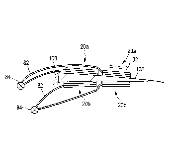
The functional principle of the trailing edge flap 120 shown in Figure 7 is
shown in detail
with reference to Figures 8a and 8b. Figures 8a and 8b show the trailing edge
or flap
region 120 enlarged and without the elastic molding material 132 in the
profile. The
carrier substrate 130, which, for example, comprises a GFRP or similar
material or
consists thereof, is shown in Figure 8a in a neutral position. That is to say
that the carrier
substrate 130 has not been deflected, which corresponds to a neutral flap
position. Both
on the upper side and on the underside, that is to say, with respect to the
rotor blade 108,
both on the suction side and on the pressure side, the carrier substrate 130
has two
actuator components 20a and 20b, respectively. The preferential direction 32
of the
respective actuator components 20a, 20b runs in the direction of the profile
chord of the
rotor blade 108. The carrier substrate 130 is attached at the front end, that
is to say the
end that points in the direction of the leading edge of the rotor blade 108,
to the rotor
blade 108.
The actuator components 20a and 20b are respectively activated by an
independent light
source 84, since the activation of the actuator components 20a may be
different from the
activation of the actuator components 20b, as further described below. Because
the
actuator components 20a are activated on the suction side, to perform an
extension in
Date Recue/Date Received 2020-08-10
CA 03090850 2020-08-10
- 25 -
the preferential direction 32, the carrier substrate 130 undergoes a bending,
which
corresponds to the changeover from the position 130a to the position 130b in
Figure 8b.
In a preferred embodiment, the actuator components 20b are activated
simultaneously in
such a way that they undergo a compression at the same time. Consequently, the
bending of the carrier substrate 130 does not have to take place counter to
the actuator
components 20b, but by contrast may even take place with their assistance. For
the
reverse process, that is to say the changeover of the carrier substrate from
the bent
position 130b to the neutral position 130a, a reverse activation of the
actuator
components 20b or 20a is necessary. For example, the actuator components 20a
may be
lo activated in such a way that they undergo a compression. Alternatively,
or preferably in
addition thereto, the actuator components 20b may be activated to undergo an
extension.
In Figure 8, the actuator components 20 are shown by way of example as
comprising
three layers, two actuator layers with an exciting layer arranged inbetween.
It goes
without saying that, in other exemplary embodiments, other configurations of
the actuator
components 20 may also be used.
In all of the embodiments, an activation, in particular by the control
component 80,
preferably comprises an illumiination, a non-illumination or any desired
combination or
intermediate stage of illumination and non-illumination, for example
illumination with
reduced intensity, with modulations, variable patterns, wavelengths, etc. A
simultaneous
activation of multiple actuator components accordingly comprises for example
also a
simultaneous activation by illumination, by non-illumination or by each of the
combinations just mentioned.
Figures 9a to 9d show a further exemplary embodiment of an actuator device 10
with a
preferential direction 32, which is perpendicular to the direction with which
the light guide
.. 82 introduces light into the exciting layer 40.
Figure 9a schematically shows a two-dimensionally configured actuator
component 20
with two actuator layers 30 and an exciting layer 40 lying inbetween. The
preferential
direction 32 corresponds to a longitudinal direction defined as L; the
individual layers of
the actuator component 20 are stacked in a thickness in the direction D and
the two-
dimensional extent of the actuator component comprises not only the
longitudinal
direction L but also a widthwise direction B. Figure 9b thus shows how the
actuator
component 20 shown in Figure 9a is rolled up along the widthwise direction B.
The
preferential direction 32 does not change thereby; that is to say that it
still runs in the
longitudinal direction L, in Figure 9b perpedicularly to the plane of the
drawing. This is
Date Recue/Date Received 2020-08-10
CA 03090850 2020-08-10
- 26 -
shown perspectively in Figure 9c. In comparison with the representation of
Figure 9a, it
can be clearly seen that the actuator device 10 requires less extent in the
widthwise
direction B. Consequently, an actuator that has the same actuator effect as
the two-
dimensional actuator shown in Figure 9a, but requiring only a fraction of the
base area,
can be realized. This is particularly advantageous for applications in which
space is
critical.
In Figure 9d, a detail of the actuator component 20 shown in Figure 9a is
schematically
and perspectively shown, while depicting the connection of the control
component 80
including the light source 84 and multiple light guides 82, which introduce
light into the
exciting layer 40 at various positions in the longitudinal direction L.
Figure 10 shows schematically and by way of example an exemplary embodiment of
the
actuator device 10, with an amplification frame 200 for transforming the
movement of the
actuator in the preferential direction 32. In this exemplary embodiment, the
actuator
component 20 is preferably configured as a stack of layers, the preferential
direction 32
corresponding to the stacking direction of the layers. The amplification frame
200
transforms the movement in the preferential direction 32 to produce as a
result an
actuator direction 220 substantially perpendicular thereto with a
transformation ratio that
can be set. For example, in this way, a push-pull rod 210 can be moved over a
much
greater distance in the actuator direction 220 than the actuator component 20
extends or
is compressed in the preferential direction 32. The design of the actuator is
similar to the
known design of a piezo stack; typical amplification factors for the
amplification frame 200
are in the range of around 5. That is to say that an extension by, for
example, 100 pm in
the preferential direction 32 results in an extension by, for example, 500 pm
along the
actuator direction 220. The amplification frame 200 is just one example of a
transformation device, and the push-pull rod 210 is also just one example of a
coupling
element; other implementations are known to a person skilled in the art.
Figure 11 shows schematically and by way of example a cross section of a rotor
blade
108 with a lift flap 230, which is controlled by two actuator devices 10, as
shown for
example in Figure 10. Each of the actuator devices 10 has the amplification
frame 200
and brings about an activation of the push-pull rods 210, so that the flap 230
is deflected
along a deflecting direction 320. In comparison with a servo flap, the lift
flap 230
substantially does not bend, but instead is mechanically displaced as a whole.
For this
purpose, preferably the two push-pull rods 210 are moved in opposite
directions, so that
there is a tilting of the flap 230 in the direction 320. Although in this
example push-pull
Date Recue/Date Received 2020-08-10
CA 03090850 2020-08-10
- 27 -
rods 210 are used as force transmitters, all other mechanical implementations
are of
course also conceivable in other exemplary embodiments.
Although lift flaps and servo flaps have been described by way of example as
active
elements in exemplary embodiments, the above advantages can also be achieved
for
other active elements, for example vortex generators and the like.
Combinations, such as
for example a combined lift and servo flap, are also advantageously
conceivable.
Figure 12 schematically shows a further exemplary embodiment of a two-
dimensionally
configured actuator component 20, as shown for example in Figure 9a. Figure 12
shows
a two-dimensional actuator, in which the extent of the actuator layers 30 and
exciting
.. layers 40 is perpendicular to the actuator area with which the actuator is
in connection
with a substrate, for example part of the rotor blade of the wind turbine. The
embodiment
can consequently be regarded as a stack actuator, from which a thin slice with
a
thickness D has been cut off and laid out flat along the widthwise direction B
and
lengthwise direction L. The arrangement allows an extension under strain in
the
preferential direction 32, which lies in the two-dimensional plane. The
preferential
direction 32 is perpendicular to the actuator layer 30, which are stacked
along the
preferential direction 32. In this exemplary embodiment, the actuator
component 20 also
comprises a mirror coating 50, which acts as a reflective layer and ensures an
optimum
introduction of the excitation light from the light guides 82 into the
exciting layers 40.
Fig. 13 shows schematically and by way of example a course of the light output
from a
light guide 82. The light yield is represented on the vertical axis, while the
course over a
length L of the light guide 82 is represented on the horizontal x axis. The
course proceeds
from an entry point 510 of the light guide 82 through the exciting layer 40 up
to an end
point 520, at which the light guide 82 ends. It can be seen that in this
simplified example,
the light yield decreases linearly with the length through the exciting layer
40.The light
yield of an oppositely aligned light guide 82' is additionally represented in
Fig. 13. The
light guide 82' consequently has the highest light yield at the end point 520
of the first
light guide 82, at which the second light guide 82' is led into the exciting
layer 40. It
consequently runs substantially oppositely to the light guide 82. If the light
guide 82 and
the light guide 82' are led in the vicinity of one another in the exciting
layer 40, an overall
light input 530 that is substantially constant over the entire length L is
obtained. The
solution according to the invention is specifically that the lowering of the
light yield in one
of the light guides 82, 82' is compensated by a further light guide, arranged
in the direct
vicinity of this light guide, being designed in a substantially opposite
manner.
Date Recue/Date Received 2020-08-10
CA 03090850 2020-08-10
- 28 -
An example of a possible arrangement of two such light guides 82, 82' is
schematically
shown with reference to Fig. 14. In this exemplary embodiment, two light
guides 82, 82'
are led over the multiplicity of edges of the exciting layers 40 of a side
surface of an
actuator stack, from an entry 820, 820' to an exit 822, 822'. The two light
guides 82, 82'
are in this case led in a meandering form, arranged substantially parallel and
respectively
offset by half an oscillation. To put it another way, one of the two light
guides 82, 82' in
each case extends in the space between two loops of the other of the light
guides 82, 82'.
In this example, the reversal of the direction of the light guides 82, 82' is
shown as
performed outside the stack consisting of exciting layers 40 and actuator
layers 30, while
the reversal of the direction of the light guides 82, 82' may for example also
be performed
within one of the exciting layers 40. It is preferred that, in the region of
the deflection of
the direction, no light yield takes place, for example by lighting means or
other surface
changes of the light guide 82, 82'. If the changes in direction of the light
guides 82, 82'
are formed within the exciting layer 40, such a light yield may however also
be provided in
the region of the reversal curves, for example by lighting means. The light
yield over the
entire exciting layer corresponds approximately to the profile 530, as it is
shown in Fig.
13, that is to say that the light yield is substantially constant over the
entire surface area
of the exciting layer 40 and also over all of the exciting layers 40.
Fig. 15 shows schematically and by way of example a further example of the
arrangement of four light guides 82, 82', 82" and 82¨, wherein each of the
light guides 82
to 82¨ is formed substantially the same and, in comparison with the exemplary
embodiment from Fig. 14, is inserted into the further light guides
respectively between the
two light guides 82, 82' shown there. Instead of the two light guides opposed
in parallel,
the arrangement of four such light guides 82 to 82¨ is consequently provided
in the
example of Fig. 15, wherein a pair - that is to say light guides 82 and 82" or
82' and 82¨ -
respectively have the same light guiding direction. The arrangement with four
light guides,
as shown in Fig. 15, makes possible uniform illumination of the exciting layer
40 with in
each case two different wavelengths or two spectral ranges on the same
actuator
surface. Preferably, one of the wavelengths, that is to say light of a certain
color, may
bring about an activation of the photoactuator of the actuator layer, while a
second
wavelength or colour deactivates the photoactuator. The designs of Fig. 14 and
Fig. 15
should of course only be understood as examples; other geometrical designs
which result
in making a homogeneous light yield of the exciting layer 40 possible are also
available to
a person skilled in the art without any difficulty. In this case, any desired
even-numbered
multiple of the two counter-running light guides can be configured.
Date Recue/Date Received 2020-08-10
CA 03090850 2020-08-10
- 29 -
Fig. 16 shows schematically and by way of example the course of a light guide
82 which
has a nano coating 830 at the distal end thereof. The nano coating 830 may for
example
be provided in the region of the exciting layer 40. The nano coating 830 has
the effect
that, in the region in which the nano coating 830 has been applied, light
leaves diffusely
in all directions around the fiber. With suitable means, a light output in
only some of the
spatial directions can of course also be realized.
Fig. 17 shows schematically and by way of example a perspective view of an
embodiment of an actuator device 10 in which multiple layers with
photoactuators 34 are
arranged stacked one on top of the other. In this schematic view, the
structure under the
photoactuator molecules is indicated by a grid; in reality, the arrangement is
of course not
restricted to this grid structure. In this example, a light guide runs in a
meandering form in
the vertical direction, perpendicularly to the direction of extent of the
individual layers 30,
40. This exemplary embodiment may preferably be combined with the arrangement
of the
light guides 82 according to Fig. 14 or Fig. 15, so that a uniform light input
is made
possible over the entire stack arrangement of the stack actuator.
Fig, 18 finally shows a further exemplary embodiment of an actuator device 10,
which in
this exemplary embodiment in the form of a cylinder is provided with an inner
bore 800.
Two light guides 82, 82' extend spirally, running oppositely around the
cylinder 810. While
in this exemplary embodiment the helix of the light guides 82, 82' is shown
around the
outside of the cylinder 810, in another exemplary embodiment it is also
possible for the
light to be guided in the middle of the cylinder 810.
Date Recue/Date Received 2020-08-10